EP4456565A1 - Instrument auditif et système auditif binaural correspondant - Google Patents
Instrument auditif et système auditif binaural correspondant Download PDFInfo
- Publication number
- EP4456565A1 EP4456565A1 EP24171624.0A EP24171624A EP4456565A1 EP 4456565 A1 EP4456565 A1 EP 4456565A1 EP 24171624 A EP24171624 A EP 24171624A EP 4456565 A1 EP4456565 A1 EP 4456565A1
- Authority
- EP
- European Patent Office
- Prior art keywords
- hearing instrument
- hearing
- electronic unit
- user
- section
- Prior art date
- Legal status (The legal status is an assumption and is not a legal conclusion. Google has not performed a legal analysis and makes no representation as to the accuracy of the status listed.)
- Pending
Links
Images


Classifications
-
- H—ELECTRICITY
- H04—ELECTRIC COMMUNICATION TECHNIQUE
- H04R—LOUDSPEAKERS, MICROPHONES, GRAMOPHONE PICK-UPS OR LIKE ACOUSTIC ELECTROMECHANICAL TRANSDUCERS; ELECTRIC HEARING AIDS; PUBLIC ADDRESS SYSTEMS
- H04R25/00—Electric hearing aids
- H04R25/40—Arrangements for obtaining a desired directivity characteristic
- H04R25/402—Arrangements for obtaining a desired directivity characteristic using contructional means
-
- H—ELECTRICITY
- H04—ELECTRIC COMMUNICATION TECHNIQUE
- H04R—LOUDSPEAKERS, MICROPHONES, GRAMOPHONE PICK-UPS OR LIKE ACOUSTIC ELECTROMECHANICAL TRANSDUCERS; ELECTRIC HEARING AIDS; PUBLIC ADDRESS SYSTEMS
- H04R25/00—Electric hearing aids
-
- H—ELECTRICITY
- H04—ELECTRIC COMMUNICATION TECHNIQUE
- H04R—LOUDSPEAKERS, MICROPHONES, GRAMOPHONE PICK-UPS OR LIKE ACOUSTIC ELECTROMECHANICAL TRANSDUCERS; ELECTRIC HEARING AIDS; PUBLIC ADDRESS SYSTEMS
- H04R25/00—Electric hearing aids
- H04R25/40—Arrangements for obtaining a desired directivity characteristic
- H04R25/405—Arrangements for obtaining a desired directivity characteristic by combining a plurality of transducers
-
- H—ELECTRICITY
- H04—ELECTRIC COMMUNICATION TECHNIQUE
- H04R—LOUDSPEAKERS, MICROPHONES, GRAMOPHONE PICK-UPS OR LIKE ACOUSTIC ELECTROMECHANICAL TRANSDUCERS; ELECTRIC HEARING AIDS; PUBLIC ADDRESS SYSTEMS
- H04R25/00—Electric hearing aids
- H04R25/55—Electric hearing aids using an external connection, either wireless or wired
- H04R25/554—Electric hearing aids using an external connection, either wireless or wired using a wireless connection, e.g. between microphone and amplifier or using Tcoils
-
- H—ELECTRICITY
- H04—ELECTRIC COMMUNICATION TECHNIQUE
- H04R—LOUDSPEAKERS, MICROPHONES, GRAMOPHONE PICK-UPS OR LIKE ACOUSTIC ELECTROMECHANICAL TRANSDUCERS; ELECTRIC HEARING AIDS; PUBLIC ADDRESS SYSTEMS
- H04R25/00—Electric hearing aids
- H04R25/60—Mounting or interconnection of hearing aid parts, e.g. inside tips, housings or to ossicles
-
- H—ELECTRICITY
- H04—ELECTRIC COMMUNICATION TECHNIQUE
- H04R—LOUDSPEAKERS, MICROPHONES, GRAMOPHONE PICK-UPS OR LIKE ACOUSTIC ELECTROMECHANICAL TRANSDUCERS; ELECTRIC HEARING AIDS; PUBLIC ADDRESS SYSTEMS
- H04R25/00—Electric hearing aids
- H04R25/60—Mounting or interconnection of hearing aid parts, e.g. inside tips, housings or to ossicles
- H04R25/602—Mounting or interconnection of hearing aid parts, e.g. inside tips, housings or to ossicles of batteries
-
- H—ELECTRICITY
- H04—ELECTRIC COMMUNICATION TECHNIQUE
- H04R—LOUDSPEAKERS, MICROPHONES, GRAMOPHONE PICK-UPS OR LIKE ACOUSTIC ELECTROMECHANICAL TRANSDUCERS; ELECTRIC HEARING AIDS; PUBLIC ADDRESS SYSTEMS
- H04R25/00—Electric hearing aids
- H04R25/60—Mounting or interconnection of hearing aid parts, e.g. inside tips, housings or to ossicles
- H04R25/604—Mounting or interconnection of hearing aid parts, e.g. inside tips, housings or to ossicles of acoustic or vibrational transducers
-
- H—ELECTRICITY
- H04—ELECTRIC COMMUNICATION TECHNIQUE
- H04R—LOUDSPEAKERS, MICROPHONES, GRAMOPHONE PICK-UPS OR LIKE ACOUSTIC ELECTROMECHANICAL TRANSDUCERS; ELECTRIC HEARING AIDS; PUBLIC ADDRESS SYSTEMS
- H04R25/00—Electric hearing aids
- H04R25/65—Housing parts, e.g. shells, tips or moulds, or their manufacture
-
- H—ELECTRICITY
- H04—ELECTRIC COMMUNICATION TECHNIQUE
- H04R—LOUDSPEAKERS, MICROPHONES, GRAMOPHONE PICK-UPS OR LIKE ACOUSTIC ELECTROMECHANICAL TRANSDUCERS; ELECTRIC HEARING AIDS; PUBLIC ADDRESS SYSTEMS
- H04R2225/00—Details of deaf aids covered by H04R25/00, not provided for in any of its subgroups
- H04R2225/025—In the ear hearing aids [ITE] hearing aids
-
- H—ELECTRICITY
- H04—ELECTRIC COMMUNICATION TECHNIQUE
- H04R—LOUDSPEAKERS, MICROPHONES, GRAMOPHONE PICK-UPS OR LIKE ACOUSTIC ELECTROMECHANICAL TRANSDUCERS; ELECTRIC HEARING AIDS; PUBLIC ADDRESS SYSTEMS
- H04R2225/00—Details of deaf aids covered by H04R25/00, not provided for in any of its subgroups
- H04R2225/31—Aspects of the use of accumulators in hearing aids, e.g. rechargeable batteries or fuel cells
-
- H—ELECTRICITY
- H04—ELECTRIC COMMUNICATION TECHNIQUE
- H04R—LOUDSPEAKERS, MICROPHONES, GRAMOPHONE PICK-UPS OR LIKE ACOUSTIC ELECTROMECHANICAL TRANSDUCERS; ELECTRIC HEARING AIDS; PUBLIC ADDRESS SYSTEMS
- H04R2225/00—Details of deaf aids covered by H04R25/00, not provided for in any of its subgroups
- H04R2225/43—Signal processing in hearing aids to enhance the speech intelligibility
-
- H—ELECTRICITY
- H04—ELECTRIC COMMUNICATION TECHNIQUE
- H04R—LOUDSPEAKERS, MICROPHONES, GRAMOPHONE PICK-UPS OR LIKE ACOUSTIC ELECTROMECHANICAL TRANSDUCERS; ELECTRIC HEARING AIDS; PUBLIC ADDRESS SYSTEMS
- H04R2225/00—Details of deaf aids covered by H04R25/00, not provided for in any of its subgroups
- H04R2225/51—Aspects of antennas or their circuitry in or for hearing aids
-
- H—ELECTRICITY
- H04—ELECTRIC COMMUNICATION TECHNIQUE
- H04R—LOUDSPEAKERS, MICROPHONES, GRAMOPHONE PICK-UPS OR LIKE ACOUSTIC ELECTROMECHANICAL TRANSDUCERS; ELECTRIC HEARING AIDS; PUBLIC ADDRESS SYSTEMS
- H04R25/00—Electric hearing aids
- H04R25/55—Electric hearing aids using an external connection, either wireless or wired
- H04R25/552—Binaural
Definitions
- the invention relates to a hearing instrument with a housing that can be worn in an ear of a user and has a concha section and a thin canal section that protrudes from the concha section.
- the invention further relates to an associated binaural hearing system.
- a hearing instrument is generally an electronic device that supports the hearing of a person wearing the hearing instrument (hereinafter referred to as the "wearer” or “user”).
- the invention relates to hearing instruments that are designed to fully or partially compensate for a hearing loss of a hearing-impaired user.
- a hearing instrument is also referred to as a "hearing aid”.
- hearing instruments that protect or improve the hearing of users with normal hearing, for example by enabling improved speech comprehension in complex hearing situations.
- Such hearing instruments are also referred to as personal sound amplification products (PSAP).
- PSAP personal sound amplification products
- the term “hearing instrument” also includes headphones with active noise cancellation (in particular so-called ear plugs, i.e. headphones worn in the ear), headsets, etc.
- Hearing instruments in general, and hearing aids in particular are usually designed to be worn on the head and in particular in or on one ear of the user, in particular as behind-the-ear devices (also known as BTE devices) or in-the-ear devices (also known as ITE devices).
- the present invention relates to the latter type of hearing instrument, i.e. ITE devices.
- Such ITE devices often have a housing with a bulbous (often roughly hemispherical) main housing part and a thin (often arm-shaped) housing extension protruding from it.
- the bulbous main housing part is adapted to be worn in the auricle (concha) and is therefore also referred to here as the "concha section” of the housing.
- the thin housing extension is designed to reach into the ear canal (canal) and is therefore also referred to here as the "canal section”.
- hearing instruments of the type described above regularly have at least one (acousto-electrical) input transducer, a signal processing unit (signal processor) and an output transducer.
- the or each input transducer receives airborne sound from the environment of the hearing instrument and converts this airborne sound into an input audio signal (i.e. an electrical signal that transports information about the ambient sound).
- the or each input audio signal is processed (i.e. modified with regard to its sound information) in order to support the user's hearing, in particular to compensate for a hearing loss of the user.
- the signal processing unit outputs a correspondingly processed audio signal to the output transducer.
- the signal processing outputs the input audio signal in its original or modified form to an external electronic device (peripheral device, e.g. another hearing instrument or a smartphone of the user) and/or receives another input audio signal from the peripheral device.
- an external electronic device e.g. another hearing instrument or a smartphone of the user
- data transmission between the hearing instrument and the peripheral device is usually wireless, e.g. using Bluetooth technology.
- Modern hearing instruments therefore often also include an antenna for wirelessly sending and receiving data.
- the output transducer is designed as an electro-acoustic transducer, which converts the (electrical) output audio signal back into airborne sound, whereby this airborne sound - modified compared to the ambient sound - into the user's ear canal.
- electro-acoustic transducers are also called "receivers”.
- a charging connection is generally an electrical device for supplying a charging current, i.e. an electrical current for charging the hearing instrument's rechargeable battery.
- Galvanic means that, in contrast to wireless charging, the charging connection enables an electrical current flow (i.e. an exchange of electrons) between a charger or charging cable and the hearing instrument.
- hearing instruments of the same type are usually manufactured in two designs that have a mirror-symmetrical outer contour.
- Hearing instruments for the left ear and hearing instruments for the right ear must therefore be manufactured separately and differently.
- internal structures for hearing instruments for the left ear and hearing instruments for the right ear must also be manufactured differently, in particular mirror-symmetrically.
- hearing instruments are often manufactured and sold as part of a binaural hearing system to serve both ears of the user.
- a binaural hearing system includes a first hearing instrument for the user's left ear and a second hearing instrument for the user's right ear.
- the invention is based on the object of simplifying the production of hearing instruments and binaural hearing systems.
- the hearing instrument comprises a housing that can be worn in a user's ear and is divided into a concha section and a thin canal section that protrudes from the concha section.
- the concha section has a bulbous shape that is adapted to the typical shape of a human auricle.
- the canal section preferably has a double-curved shape (in different planes) that is adapted to the typical anatomy of the human ear canal.
- the hearing instrument is preferably a standard device (one-fits-all device) that is offered with the same housing shape for a large number of users.
- the hearing instrument can also be an individually adapted hearing instrument in which the shape of the concha section and the canal section is precisely adapted to the specific shape of the auricle and ear canal of the individual user.
- the hearing instrument also includes a battery, a signal processor, at least two microphones and a receiver (i.e. an electro-acoustic output transducer).
- At least the battery, the signal processor and the microphones are arranged in a mechanically rigid electronic unit which is accommodated in the concha section.
- the earpiece on the other hand, is preferably separated (and mechanically decoupled) from the electronic unit and at least partially accommodated in the canal section.
- the earpiece is preferably arranged (fully or partially) in the canal section in such a way that it is not in a direct (immediate) mechanical connection with the electronic unit.
- the side of the electronic unit that faces away from the user's head when the hearing instrument is in the intended wearing position in the user's ear is referred to below as the “top” of the electronic unit.
- the side of the electronic unit opposite this top, which faces the user's head when the hearing instrument is in the intended wearing position, is referred to accordingly as the “bottom” of the electronic unit.
- each of the two microphones is arranged on the top of the electronic unit so that it is centered with respect to a horizontal plane.
- the microphones are arranged on the electronic unit in such a way that the horizontal plane intersects a sound inlet of the respective microphone in the middle.
- the "horizontal plane" of the concha section and the electronic unit placed therein is a plane that, when the hearing instrument is being worn, is aligned approximately (i.e. exactly or approximately) parallel to the transverse plane of the user's head and intersects the concha section of the housing in the middle.
- the transverse plane of the head is the plane perpendicular to the longitudinal direction of the head that separates the lower half of the head from the upper half of the head.
- the horizontal plane is referred to as approximately parallel to the transverse plane of the user's head (and thus according to the invention) in particular when it is inclined by up to 20° (preferably by up to 10°) with respect to the transverse plane of the head in the intended wearing position of the hearing instrument in the user's ear.
- the arrangement of the microphones on the electronic unit makes it possible to use the electronic unit in an identical design in both hearing instruments for the right ear and in hearing instruments for the left ear.
- Adapting the electronic unit to the right or left ear is limited to rotating the electronic unit by 180° around a central axis of the electronic unit, which is formed by the intersection of the horizontal plane and the vertical plane.
- one and the same electronic unit could be removed from a hearing instrument designed for the left ear and - rotated by 180° - inserted into a hearing instrument designed for the right ear.
- the arrangement of the microphones on the electronic unit described above ensures in particular that, in the intended wearing position of the hearing instrument in the left or right ear of the user, the at least two microphones each assume a corresponding relative position with respect to the left or right half of the user's head; in other words, in a binaural hearing system, the two hearing instruments in the intended wearing position have microphone arrangements that are mirror-symmetrical to one another (i.e. mirrored on the sagittal plane of the head).
- the same microphone (front microphone) of the electronic unit is always arranged further forward, i.e. closer to the user's face, than the other microphone (rear microphone).
- the electronic unit and all of its sub-components only need to be manufactured in a single design in order to equip hearing instruments for the right ear and hearing instruments for the left ear. Since the electronic unit is by far the most complex and, in terms of production effort, Since this is the most complex sub-unit of the hearing instrument, this considerably simplifies production.
- an antenna for electromagnetic (and thus wireless) data transmission e.g. between the hearing instrument and a smartphone and/or between the two hearing instruments of a binaural hearing system, is additionally arranged in the electronic unit.
- a base point (i.e. a central feed point) of the antenna is preferably arranged centered with respect to the horizontal plane on the electronic unit. This makes it possible to use the electronic unit comprising the antenna with comparable transmission and reception characteristics on both sides of the head.
- the base point of the antenna is arranged in particular on an edge of the top of the electronic unit facing away from the canal section of the housing.
- the battery is preferably a rechargeable battery.
- an electrical charging connection for charging the battery i.e. for the galvanic supply of an electrical charging current
- the charging connection which is designed in particular as a contact surface for contact with a corresponding counter-contact surface or alternatively as a charging socket for receiving a corresponding charging plug, is preferably arranged centered with respect to the horizontal plane.
- the charging connection is also preferably axially symmetrical (or, equivalently formulated, rotationally symmetrical with respect to a 180° rotation around an axis of the charging connection (lying in the horizontal plane).
- Another embodiment of the invention is a binaural hearing system.
- This comprises a first hearing instrument for the user's left ear and a second hearing instrument for the user's right ear.
- Both hearing instruments are mirror-inverted (in particular with respect to a plane that is parallel to the horizontal plane). vertical vertical plane), but otherwise (at least substantially) structurally identical in the manner according to the invention described above, in particular in one of the variants of the invention described above.
- the two hearing instruments of the binaural hearing system have identically designed electronic units.
- the electronic unit of the first hearing instrument and the electronic unit of the second hearing instrument are in particular rotated by 180° to each other and inserted into the housings of the first and second hearing instruments, which are arranged mirror-symmetrically to each other.
- the electronic unit of the first hearing instrument can be mapped onto the electronic unit of the second hearing instrument by a 180° rotation about a central axis forming the intersection line of the horizontal plane and the vertical plane, if the housings of the two hearing instruments are arranged mirror-symmetrically to each other.
- the two hearing instruments preferably also have identically designed receivers.
- the Fig. 1 to 14 show a hearing instrument 2, which is, for example, a hearing aid, ie a hearing instrument designed to support the hearing of a hearing-impaired user.
- the hearing instrument 2 is designed as an ITE hearing instrument that can be inserted into the ear of a user.
- the Fig. 1 to 14 The hearing instrument 2 shown is designed for insertion into the user’s left ear.
- the hearing instrument 2 comprises a housing 4 which is divided into a concha section 6 and a canal section 8 protruding from the concha section.
- the Fig. 2 shows the hearing instrument 2 in a plan view transverse to a horizontal plane H.
- the horizontal plane H cuts the concha section 6 in the middle.
- the horizontal plane H is approximately parallel to the transverse plane of the user's head and thus, when the head is in an upright position, is aligned approximately horizontally in the surrounding space.
- the transverse plane of the head is the plane perpendicular to the longitudinal direction of the head that separates the lower half of the head from the upper half of the head.
- the Fig. 3 shows the hearing instrument 2 in plan view transverse to a vertical plane V.
- the vertical plane V also intersects the concha section 6 centrally and perpendicular to the horizontal plane H.
- the vertical plane V is approximately parallel to the coronal plane (also: frontal plane) of the user's head and thus, when the head is held upright, is aligned approximately vertically in the surrounding space.
- the coronal or frontal plane of the head is the plane parallel to the longitudinal direction of the head that separates the front half of the head from the back half of the head.
- the projection of the horizontal plane H or the vertical plane V shown in each case also shows the position of the intersection line of these two planes. This intersection line is also referred to below as the central axis Z of the hearing instrument 2.
- the concha section 6 has a bulbous shape, adapted to the typical shape of a human auricle (concha).
- the canal section 8 has a thin and elongated shape, adapted to the typical anatomy of the human ear canal (canal).
- the canal section 8 has a first curvature that is at least approximately in the horizontal plane H, which Fig. 2 by a first angle W1.
- the canal section 8 has a second curvature lying at least approximately in the vertical plane V, which Fig. 3 indicated by a second angle W2.
- the housing 4 is made up of two assembled housing parts, namely a housing tray 10 and a housing cover 12.
- the housing tray 10 forms a bottom side 14 of the concha section 6, which faces the user's head in the intended wearing position of the hearing instrument 2.
- Both the housing tray 10 and the housing cover 12 also form one side of the canal section 8.
- the side of the canal section 8 formed by the housing tray 10 is referred to as the bottom side 18 and the side of the canal section 8 formed by the housing cover 12 is referred to as the top side 20.
- connection piece 22 for connecting an ear mold is also formed on the underside 18 of the canal section 8.
- the umbrella- or funnel-shaped ear mold (not shown) serves to fix the hearing instrument 2 in the auditory canal and to completely or partially acoustically seal the inner auditory canal from the environment.
- the housing tray 10 and the housing cover 12 are in the assembled state according to Fig. 1 to 3 by snap connections 24 ( Fig. 8 , 9 ) are attached to each other in a non-destructive manner.
- the hearing instrument 2 comprises Fig. 4 to 8 and 13 and 14 two microphones 26 as input transducers and a receiver 28 as output transducer.
- the hearing instrument 2 further comprises a battery 30 and a (particularly digital) signal processor 32.
- the signal processor 32 comprises both a programmable subunit (for example a microprocessor) and a non-programmable subunit (for example an ASIC).
- the signal processor 32 is supplied with an electrical supply voltage from the battery 30.
- the microphones 26 record airborne sound from the environment of the hearing instrument 2.
- the microphones 26 convert the sound into an (input) audio signal that contains information about the recorded sound.
- the input audio signals are fed to the signal processor 32 within the hearing instrument 2, which modifies these input audio signals to support the user's hearing.
- the signal processor 32 outputs an output audio signal that contains information about the processed and thus modified sound to the receiver 28.
- the receiver 28 converts the output sound signal into modified airborne sound. This modified airborne sound is then emitted into the user's ear canal.
- the battery 30 is a rechargeable battery.
- the hearing instrument 2 includes a galvanic charging connection 34.
- this charging connection 34 is formed by a plug connector that is connected to an electronic charging control (not explicitly shown) of the hearing instrument 2.
- the hearing instrument 2 is inserted into a corresponding receptacle of a charging device (not shown) so that the charging connection 34 of the hearing instrument 2 contacts a corresponding mating connector of the charging device.
- the hearing instrument 2 comprises an antenna 38 within the housing 4, which enables wireless data exchange between the hearing instrument 2 and at least one other electronic device, e.g. another hearing instrument and/or a smartphone of the user.
- the antenna 38 is designed to send and receive electromagnetic waves, in particular in the GHz range.
- the data transmission preferably takes place on the basis of the Bluetooth standard.
- the microphones 26, the battery 30, the signal processor 32, the charging connection 34, the charging control and the antenna 38 are part of an electronic unit 40, which is held together as a rigid structural unit by an electronic frame 42 (formed in particular by a plastic part).
- the electronic unit 40 further comprises an amplifier (not explicitly shown) which amplifies the output audio signal output by the signal processor before it is output by the earpiece 28.
- the electronics unit 40 is inserted into the concha section 6 of the housing 4 and essentially fills this concha section 6.
- the receiver 28 is not arranged in the electronic unit 40, but is located spatially and mechanically separated from it in the canal section 8 of the housing 4.
- the receiver 28 is accommodated in a damping body 44 made of elastic material, which acoustically dampens the receiver 28 relative to the housing 4 and thus suppresses the transmission of the structure-borne sound generated by the receiver 28 (i.e. the mechanical vibration of the receiver 28 when the sound signal is emitted).
- the damping body 44 has a hardness (Shore hardness SHA) between 50° and 70° and consists, for example, of a fluoroelastomer (e.g. Viton/FKM).
- the damping body 44 comprises a pocket 46 in which the earpiece 28 is inserted through an open rear longitudinal end 48 (see in particular Fig. 13 ).
- the pocket 46 is preferably slightly smaller in size than the earpiece 28, so that the earpiece 28 is fixed in place by the elastic material of the pocket 46.
- the damping body 44 with the inserted earpiece 28 is inserted into the canal section 8 in such a way that the longitudinal end 48 faces the concha section 6 (see. Fig. 4 and 11 to 14 ).
- the pocket 46 is provided with two opposing cutouts which, in the assembly position, face the underside 18 or the top of the canal section 8. These cutouts save material, weight and installation space.
- the damping body 44 further comprises a short hose-like (and thus in particular hollow) sound nozzle 50, which is integrally formed on a front longitudinal end 52 of the pocket 46 opposite the longitudinal end 48.
- a sound outlet of the earpiece 28 is such arranged in the region of the front longitudinal end 52 of the pocket 46 so that the sound generated by the earpiece 28 is emitted into the sound nozzle 50.
- the sound nozzle 50 is attached to the pocket 46 at an angle to the longitudinal axis of the pocket 46, corresponding to the first angle W1.
- the second curvature of the canal section 8 is not completely reproduced on the damping body 44. Instead, the sound nozzle 50 ends at its end facing away from the pocket 46 in a support plate 54, which is set at an angle to the axis of the sound nozzle 50. With the support plate 54, the sound nozzle 50 rests all around on a shoulder 56 of the canal section 8 (formed on an inner wall of the canal section 8).
- the sound nozzle 50 extends - corresponding to the second angle W2 - obliquely to the end of the canal section 8 formed by the connection nozzle 22. Due to the support plate 54 resting on the shoulder 56, the transition between the sound nozzle 50 of the damping body 44 and the end nozzle 22 of the housing 4 is also acoustically sealed.
- the damping body 44 lies essentially stress-free in the canal section 8; in the assembly position, it is therefore neither significantly compressed nor stretched nor bent nor twisted nor sheared.
- the support plate 54 is wider than the sound nozzle 50. It therefore has an outer edge that protrudes from an outer circumference of the sound nozzle 50.
- the support plate 54 thereby almost completely fills the hollow inner cross section of the canal section 8 in the area of the shoulder 56; however, the outer diameter of the support plate 54 is preferably slightly (in particular by approx. 10%) smaller than the locally corresponding inner diameter of the canal section 8.
- the lower end of the damping body 44 is thus centered (self-centered) in the canal section 8 of the housing 4 by the widened support plate 54 without any further measures, without the damping body 44 being clamped or even compressed by the housing wall.
- the sound nozzle 50 is guided with a distance from the housing wall on all sides.
- the damping body 44 is only fixed to the housing 4 by a T-shaped retaining projection 60.
- the elastic retaining projection 60 formed on the underside of the longitudinal end 48 (therefore opposite to the support plate 54 and on the inside with respect to the bend of the damping body 44) on the pocket 46 is pressed into a retaining contour 62 of the housing pan 10, which fixes the retaining projection 60 in a form-fitting and force-fitting manner.
- the retaining contour 62 preferably encloses a crossbar of the T-shaped retaining projection 60 (i.e. the "roof" of the T-shape) from both sides.
- the damping body 44 In the area between the retaining projection 60 and the support plate 54, the damping body 44 is not in contact with the housing wall in its rest position. However, the damping body 44 is additionally provided with several lugs 64 that protrude outward from the pocket 46 (namely in the assembly position in the direction of the underside 18 and the top 20 of the canal section 8), which are made of the elastic material of the damping body 44 and buffer the damping body 46 against the housing wall when it is deflected more strongly from the rest position under the effect of internal or external accelerations. In the rest position and when the damping body 44 is deflected only slightly, the lugs 64 preferably do not touch the housing wall ( Fig. 14 ).
- damping body 44 is only fixed to the support plate 54 and to the retaining projection 60 on the housing 4, it can move largely freely laterally (i.e. transversely to its longitudinal direction).
- the electronic unit 40 is connected to the concha section 6 of the housing 4 at only three points, namely via two elastic sealing rings 66, each of which is arranged in alignment with one of the two microphones 26 and between the respective Microphone 26 and the housing cover 12, as well as a further elastic sealing ring 68 which surrounds the charging connection 34.
- the sealing rings 66 and 68 serve on the one hand to seal the interior of the housing 4 from the environment against moisture, dirt and noise in the area of a respective associated housing opening (as a sound inlet for a respective associated microphone 26 or as an access opening for the charging connection 34).
- the three sealing rings 66 and 68 serve as cushioning elements which effectively decouple the electronics unit 40 from vibrations transmitted via the housing 4 (in particular the structure-borne noise generated by the earpiece 28).
- the electronics unit 40 is thus suspended in the concha section 6 of the housing 4 via the only three connection points with the housing 4, so to speak in a floating manner (i.e. without hard contact).
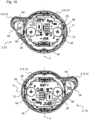
- a binaural hearing system 70 which consists of the hearing instrument 2 according to Fig. 1 to 14 and another hearing instrument 2' for the user's right ear.
- the hearing instrument 2 ⁇ shown without the housing cover has a housing 4 ⁇ which is mirror-symmetrical (i.e. mirrored on the vertical plane V) to the housing 4 of the hearing instrument 2. Furthermore, the hearing instrument 2' also has a damping body 44' which is mirror-symmetrical to the damping body 44 of the hearing instrument 2.
- the remaining components, in particular the receiver 28 and the electronic unit 40, are identical in both hearing instruments 2 and 2'.
- the electronic unit 40 of the hearing instrument 2' is, in comparison to the electronic unit 40 of the hearing instrument 2, arranged in a direction rotated by 180° around the central axis Z (ie in the plane of the drawing of the Fig. 15 ) rotated position in the housing 4'.
- Microphones 26 of both hearing instruments 2 and 2' have a corresponding position and thus a corresponding spatial recording area in the wearing position on the left or right ear of the user.
- the use of identical electronic units 40 for the left hearing instrument 2 and the right hearing instrument 2' is also facilitated by the fact that a base point 72 (ie a central feed point) of the antenna 38 on the electronic unit 40 is also arranged in the horizontal plane H and centered with respect to this (see. Fig. 4 and 8 ). This achieves the effect that the base points 72 of the antennas 38 in both hearing instruments 2 and 2' are arranged in a corresponding position in the wearing position, whereby a corresponding radiation characteristic is achieved for both antennas 38.
- the invention is particularly clear from the embodiment described above, but is in no way limited to this example. Rather, further embodiments of the invention can be derived from the above description within the scope of the claims.
- the invention is not limited to hearing aids, but can generally be applied to hearing instruments that can be worn in the ear.
Landscapes
- Engineering & Computer Science (AREA)
- Health & Medical Sciences (AREA)
- General Health & Medical Sciences (AREA)
- Neurosurgery (AREA)
- Otolaryngology (AREA)
- Physics & Mathematics (AREA)
- Acoustics & Sound (AREA)
- Signal Processing (AREA)
- Computer Networks & Wireless Communication (AREA)
- Manufacturing & Machinery (AREA)
- Headphones And Earphones (AREA)
Applications Claiming Priority (1)
| Application Number | Priority Date | Filing Date | Title |
|---|---|---|---|
| DE102023203769.6A DE102023203769A1 (de) | 2023-04-24 | 2023-04-24 | Hörinstrument und zugehöriges binaurales Hörsystem |
Publications (1)
| Publication Number | Publication Date |
|---|---|
| EP4456565A1 true EP4456565A1 (fr) | 2024-10-30 |
Family
ID=90826603
Family Applications (1)
| Application Number | Title | Priority Date | Filing Date |
|---|---|---|---|
| EP24171624.0A Pending EP4456565A1 (fr) | 2023-04-24 | 2024-04-22 | Instrument auditif et système auditif binaural correspondant |
Country Status (4)
| Country | Link |
|---|---|
| US (1) | US12701371B2 (fr) |
| EP (1) | EP4456565A1 (fr) |
| CN (1) | CN118843055A (fr) |
| DE (1) | DE102023203769A1 (fr) |
Families Citing this family (1)
| Publication number | Priority date | Publication date | Assignee | Title |
|---|---|---|---|---|
| US20260172765A1 (en) * | 2024-12-13 | 2026-06-18 | Oticon A/S | Hearing aid with integrated slot antenna |
Citations (3)
| Publication number | Priority date | Publication date | Assignee | Title |
|---|---|---|---|---|
| US20160050474A1 (en) * | 2014-08-12 | 2016-02-18 | Google Technology Holdings LLC | Circuit Assembly for Compact Acoustic Device |
| WO2022260242A1 (fr) * | 2021-06-10 | 2022-12-15 | 삼성전자 주식회사 | Dispositif électronique comprenant un module de microphone |
| EP4164251A2 (fr) * | 2023-01-25 | 2023-04-12 | Oticon A/s | Appareil auditif |
Family Cites Families (3)
| Publication number | Priority date | Publication date | Assignee | Title |
|---|---|---|---|---|
| CH681125A5 (en) | 1990-07-20 | 1993-01-15 | Phonak Ag | Ventilated in-ear hearing aid - has openings in opposite end faces of housing saving wearer from unpleasant ear plug feeling |
| CN216751213U (zh) | 2021-08-27 | 2022-06-14 | 深圳市婕妤达电子有限公司 | 一种助听器组件 |
| DE102021210075A1 (de) | 2021-09-13 | 2022-10-20 | Sivantos Pte. Ltd. | Hörinstrumentesystem |
-
2023
- 2023-04-24 DE DE102023203769.6A patent/DE102023203769A1/de active Pending
-
2024
- 2024-04-22 EP EP24171624.0A patent/EP4456565A1/fr active Pending
- 2024-04-23 CN CN202410489888.3A patent/CN118843055A/zh active Pending
- 2024-04-24 US US18/644,399 patent/US12701371B2/en active Active
Patent Citations (3)
| Publication number | Priority date | Publication date | Assignee | Title |
|---|---|---|---|---|
| US20160050474A1 (en) * | 2014-08-12 | 2016-02-18 | Google Technology Holdings LLC | Circuit Assembly for Compact Acoustic Device |
| WO2022260242A1 (fr) * | 2021-06-10 | 2022-12-15 | 삼성전자 주식회사 | Dispositif électronique comprenant un module de microphone |
| EP4164251A2 (fr) * | 2023-01-25 | 2023-04-12 | Oticon A/s | Appareil auditif |
Also Published As
| Publication number | Publication date |
|---|---|
| US12701371B2 (en) | 2026-08-04 |
| DE102023203769A1 (de) | 2024-10-24 |
| CN118843055A (zh) | 2024-10-25 |
| US20240357297A1 (en) | 2024-10-24 |
Similar Documents
| Publication | Publication Date | Title |
|---|---|---|
| DE112008002187B4 (de) | Hinter-dem-Ohr-Hörhilfe, deren Mikrophon in einen Eingang des Ohrkanals gesetzt ist | |
| EP2534855B1 (fr) | Appareil auditif derrière l'oreille à connecteur enfichable | |
| DE102013204681B4 (de) | Binaurales Hörinstrument sowie Ohrstück | |
| EP2680611B1 (fr) | Connecteur d'instrument auditif hybride | |
| EP2219392B1 (fr) | Module de microphone pour un dispositif auditif | |
| DE112020005574T5 (de) | Tonausgabevorrichtung | |
| DE102023203769A1 (de) | Hörinstrument und zugehöriges binaurales Hörsystem | |
| DE102018207918A1 (de) | Verfahren zum Laden eines im Gehörgang getragenen elektrischen Geräts, elektrisches Gerät, Lademodul und Hörsystem | |
| DE102005006404B3 (de) | Modulares Hörgerätesystem | |
| US9485594B2 (en) | Connector arrangement in hearing instruments | |
| CN114584885A (zh) | 具有倾斜麦克风/接收器的听力设备耳机 | |
| EP4456558A1 (fr) | Instrument auditif et système auditif binaural correspondant | |
| DE102008052682B4 (de) | Hörereinrichtung mit beweglichem Hörer | |
| EP4456564A1 (fr) | Instrument auditif et système auditif binaural correspondant | |
| EP3739906A1 (fr) | Instrument auditif | |
| DE102018111742A1 (de) | Hörsystem und ein Verfahren zum Betrieb eines Hörsystems | |
| US11770652B2 (en) | Hearing device earpiece having intermediate module | |
| DE202025106891U1 (de) | Am Ohr getragene Hörvorrichtung mit Im-Ohr-Sensor | |
| DE202025106893U1 (de) | Am Ohr getragene Hörvorrichtung mit Im-Ohr-Mikrofon | |
| EP2852182A1 (fr) | Appareil auditif doté d'un interrupteur de compartiment de batterie | |
| DE202023106283U1 (de) | Am Ohr getragene Hörvorrichtung und am Ohr getragene Akustikwandler-Unterbaugruppe | |
| DE102014219017A1 (de) | Hörinstrument mit Energieversorgungseinrichtung und Hörinstrumentensystem mit Energieversorgungseinrichtung | |
| DE202025107178U1 (de) | Am Ohr getragene Hörvorrichtung mit Im-Ohr-Mikrofon | |
| DE202025102785U1 (de) | Schallerzeugender Wandler für am Ohr getragene Hörvorrichtung | |
| DE102007037660A1 (de) | Hörvorrichtung mit angepassten Komponenten |
Legal Events
| Date | Code | Title | Description |
|---|---|---|---|
| PUAI | Public reference made under article 153(3) epc to a published international application that has entered the european phase |
Free format text: ORIGINAL CODE: 0009012 |
|
| STAA | Information on the status of an ep patent application or granted ep patent |
Free format text: STATUS: THE APPLICATION HAS BEEN PUBLISHED |
|
| AK | Designated contracting states |
Kind code of ref document: A1 Designated state(s): AL AT BE BG CH CY CZ DE DK EE ES FI FR GB GR HR HU IE IS IT LI LT LU LV MC ME MK MT NL NO PL PT RO RS SE SI SK SM TR |
|
| STAA | Information on the status of an ep patent application or granted ep patent |
Free format text: STATUS: REQUEST FOR EXAMINATION WAS MADE |
|
| 17P | Request for examination filed |
Effective date: 20250417 |