EP4456602A2 - Procédé et système de routage de données pour un utilisateur à partage de ressources au niveau d'une station de base cellulaire pour une architecture de réseau à double connectivité - Google Patents
Procédé et système de routage de données pour un utilisateur à partage de ressources au niveau d'une station de base cellulaire pour une architecture de réseau à double connectivité Download PDFInfo
- Publication number
- EP4456602A2 EP4456602A2 EP24172759.3A EP24172759A EP4456602A2 EP 4456602 A2 EP4456602 A2 EP 4456602A2 EP 24172759 A EP24172759 A EP 24172759A EP 4456602 A2 EP4456602 A2 EP 4456602A2
- Authority
- EP
- European Patent Office
- Prior art keywords
- leg
- gnb
- ddr
- lte
- ddds
- Prior art date
- Legal status (The legal status is an assumption and is not a legal conclusion. Google has not performed a legal analysis and makes no representation as to the accuracy of the status listed.)
- Pending
Links
Images









Classifications
-
- H—ELECTRICITY
- H04—ELECTRIC COMMUNICATION TECHNIQUE
- H04W—WIRELESS COMMUNICATION NETWORKS
- H04W28/00—Network traffic management; Network resource management
- H04W28/02—Traffic management, e.g. flow control or congestion control
- H04W28/08—Load balancing or load distribution
- H04W28/09—Management thereof
- H04W28/0958—Management thereof based on metrics or performance parameters
-
- H—ELECTRICITY
- H04—ELECTRIC COMMUNICATION TECHNIQUE
- H04W—WIRELESS COMMUNICATION NETWORKS
- H04W28/00—Network traffic management; Network resource management
- H04W28/02—Traffic management, e.g. flow control or congestion control
- H04W28/08—Load balancing or load distribution
Definitions
- the present disclosure relates to systems and methods for radio access networks.
- the present disclosure is related to the design of operation, administration and management of various network elements of 4G, 5G, and further generations of a radio system.
- the method is performed by a computer system that comprises one or more processors and a computer-readable storage medium encoded with instructions executable by at least one of the processors and operatively coupled to at least one of the processors.
- method comprises:
- the method can further comprise computing a LTE DDR Factor ddrFactorLTE and a NR DDR factor ddrFactorNR are configured to operate on the received DDR on either or both of the 4G leg or the 5G leg.
- the method can further comprise the intermediate factor being computed as the ratio of DDR received in the respective 4G leg and the 5G leg to the sum of a latest of the DDRs received in DDDS from both the4G leg and the 5G leg.
- the method can further comprise:
- the method can further comprise:
- the method can further comprise: processing, at the gNB CU-UP or a RAN Intelligent Controller (RIC), midhaul quality parameters in the DDDS to determine the quality of the4G leg and the 5G leg.
- the midhaul quality parameters further comprise:
- the method can further comprise:
- the method can further comprise: transmitting all the packets on only the operative leg until the DDDS message includes cause value including a Radio Link resume.
- the method can further comprise: computing and maintaining a final Split Factor per 4G leg and 5G leg.
- the method can further comprise:
- a method comprises:
- a method comprises:
- the method can further comprise:
- the method can further comprise:
- the policy for execution can be one or more of:
- RAN Radio Access Networks
- CU central unit
- DU distributed unit
- BBUs baseband units
- CUs are usually located in the cloud on commercial off the shelf servers, while DUs can be distributed. while the RF and real-time critical functions can be processed in the remote radio unit (RU).
- FIG. 1 is a block diagram of a system 100 for implementations as described herein.
- System 100 includes a NR UE 101, a NR gNB 106.
- the NR UE and NR gNB 106 are communicatively coupled via a Uu interface 120.
- NR UE 101 includes electronic circuitry, namely circuitry 102, that performs operations on behalf of NR UE 101 to execute methods described herein.
- Circuity 102 may be implemented with any or all of (a) discrete electronic components, (b) firmware, and (c) a programmable circuit 102A.
- NR gNB 106 includes electronic circuitry, namely circuitry 107, that performs operations on behalf of NR gNB 106 to execute methods described herein.
- Circuity 107 may be implemented with any or all of (a) discrete electronic components, (b) firmware, and (c) a programmable circuit 107A.
- Programmable circuit 107A which is an implementation of circuitry 107, includes a processor 108 and a memory 109.
- Processor 108 is an electronic device configured of logic circuitry that responds to and executes instructions.
- Memory 109 is a tangible, non-transitory, computer-readable storage device encoded with a computer program.
- memory 109 stores data and instructions, i.e., program code, that are readable and executable by processor 108 for controlling operations of processor 108.
- Memory 109 may be implemented in a random-access memory (RAM), a hard drive, a read only memory (ROM), or a combination thereof.
- One of the components of memory 109 is a program module, namely module 110.
- Module 110 contains instructions for controlling processor 108 to execute operations described herein on behalf of NR gNB 106.
- module is used herein to denote a functional operation that may be embodied either as a stand-alone component or as an integrated configuration of a plurality of subordinate components.
- each of module 105 and 110 may be implemented as a single module or as a plurality of modules that operate in cooperation with one another.
- Storage device 130 is a tangible, non-transitory, computer-readable storage device that stores module 110 thereon.
- Examples of storage device 130 include (a) a compact disk, (b) a magnetic tape, (c) a read only memory, (d) an optical storage medium, (e) a hard drive, (f) a memory unit consisting of multiple parallel hard drives, (g) a universal serial bus (USB) flash drive, (h) a random-access memory, and (i) an electronic storage device coupled to NR gNB 106 via a data communications network.
- Uu Interface (120) is the radio link between the NR UE and NR gNB, which is compliant to the 5G NR specification.
- UEs 101 can be dispersed throughout a wireless communication network, and each UE may be stationary or mobile.
- a UE includes: an access terminal, a terminal, a mobile station, a subscriber unit, a station, etc.
- a UE can also include be a cellular phone (e.g., a smart phone), a personal digital assistant (PDA), a wireless modem, a wireless communication device, a handheld device, a laptop computer, a cordless phone, a wireless local loop (WLL) station, a tablet, a camera, a gaming device, a drone, a robot/robotic device, a netbook, a smartbook, an ultrabook, a medical device, medical equipment, a healthcare device, a biometric sensor/device, a wearable device such as a smart watch, smart clothing, smart glasses, a smart wristband, and/or smart jewelry (e.g., a smart ring, a smart bracelet, etc.), an entertainment device (e.g., a music device
- UEs can include UEs considered as machine-type communication (MTC) UEs or enhanced/evolved MTC (eMTC) UEs.
- MTC/eMTC UEs that can be implemented as IoT UEs.
- IoT UEs include, for example, robots/robotic devices, drones, remote devices, sensors, meters, monitors, cameras, location tags, etc., that can communicate with a BS, another device (e.g., remote device), or some other entity.
- a wireless node can provide, for example, connectivity for or to a network (e.g., a wide area network such as Internet or a cellular network) via a wired or wireless communication link.
- a network e.g., a wide area network such as Internet or a cellular network
- One or more UEs 101 in the wireless communication network can be a narrowband bandwidth UE.
- narrowband UEs devices with limited communication resources, e.g. smaller bandwidth, are considered as narrowband UEs.
- legacy devices such as legacy and/or advanced UEs can be considered as wideband UEs.
- Wideband UEs are generally understood as devices that use greater amounts of bandwidth than narrowband UEs.
- the UEs 101 are configured to connect, for example, communicatively couple, with an or RAN.
- the RAN may be an NG RAN or a 5G RAN, an E-UTRAN, an MF RAN, or a legacy RAN, such as a UTRAN or GERAN.
- NG RAN refers to a RAN 110 that operates in an NR or 5G system
- E-UTRAN refers to a RAN that operates in an LTE or 4G system
- MF RAN refers to a RAN that operates in an MF system 100.
- the UEs 101 utilize connections (or channels), respectively, each of which comprises a physical communications interface or layer.
- the physical DL channels include the PDSCH, PMCH, PDCCH, EPDCCH, MPDCCH, R-PDCCH, SPDCCH, PBCH, PCFICH, PHICH, NPBCH, NPDCCH, NPDSCH, and/or any other physical DL channels mentioned herein.
- the physical UL channels include the PRACH, PUSCH, PUCCH, SPUCCH, NPRACH, NPUSCH, and/or any other physical UL channels mentioned herein.
- the RAN can include one or more AN nodes or RAN nodes. These access nodes can be referred to as BS, gNBs, RAN nodes, eNBs, NodeBs, RSUs, MF-APs, TRxPs or TRPs, and so forth, and comprise ground stations (e.g., terrestrial access points) or satellite stations providing coverage within a geographic area (e.g., a cell).
- NG RAN node refers to a RAN node that operates in an NR or 5G system (e.g., a gNB), and the term “E-UTRAN node” or the like refers to a RAN node that operates in an LTE or 4G system (e.g., an eNB).
- the RAN nodes can be implemented as one or more of a dedicated physical device such as a macrocell base station, and/or a low power base station for providing femtocells, picocells or other like cells having smaller coverage areas, smaller user capacity, or higher bandwidth compared to macrocells.
- all or parts of the RAN nodes can be implemented as one or more software entities running on server computers as part of a virtual network, which may be referred to as a CRAN and/or a vBBU.
- the CRAN or vBBU may implement a RAN function split, such as a PDCP split wherein RRC and PDCP layers are operated by the CRAN/vBBU and other L2 protocol entities are operated by individual RAN nodes; a MAC/PHY split wherein RRC, PDCP, RLC, and MAC layers are operated by the CRAN/vBBU and the PHY layer is operated by individual RAN nodes; or a "lower PHY" split wherein RRC, PDCP, RLC, MAC layers and upper portions of the PHY layer are operated by the CRAN/vBBU and lower portions of the PHY layer are operated by individual RAN nodes.
- a RAN function split such as a PDCP split wherein RRC and PDCP layers are operated by the CRAN/vB
- an individual RAN node can represent individual gNB-DUs that are connected to a gNB-CU 151via individual F1 interfaces.
- the gNB-DUs may include one or more remote radio heads (RRH), and the gNB-CU 151may be operated by a server that is located in the RAN or by a server pool in a similar manner as the CRAN/vBBU.
- RRH remote radio heads
- ng-eNBs next generation eNBs
- MF-APs are entities that provide MultiFire radio services, and may be similar to eNBs in an 3GPP architecture.
- a scheduling entity e.g.: BS, gNB, etc.
- a scheduling entity can be configured to schedule, assign, reconfigure, and release resources for one or more subordinate entities.
- a UE 101 (or other device) may function as master node scheduling entity, scheduling resources for one or more secondary node subordinate entities (e.g., one or more other UEs 101).
- a scheduling entity and one or more subordinate entities may communicate utilizing the scheduled resources.
- BS or gNB 106 may be equipped with T antennas and UE 101 may be equipped with R antennas, where in general T ⁇ 1 and R ⁇ 1.
- a transmit processor is configured to receive data from a data source for one or more UEs 101 and select one or more modulation and coding schemes (MCS) for each UE based on channel quality indicators (CQIs) received from the UE 101.
- MCS modulation and coding schemes
- CQIs channel quality indicators
- the BS is configured to process (e.g., encode and modulate) the data for each UE 101 based on the MCS(s) selected for the UE 101, and provide data symbols for all UEs.
- a transmit processor is also configured to process system information (e.g., for static resource partitioning information (SRPI), etc.) and control information (e.g., CQI requests, grants, upper layer signaling, etc.) and can provide overhead symbols and control symbols.
- Processor 108 may also generate reference symbols for reference signals (e.g., the cell-specific reference signal (CRS)) and synchronization signals (e.g., the primary synchronization signal (PSS) and the secondary synchronization signal (SSS)).
- reference signals e.g., the cell-specific reference signal (CRS)
- synchronization signals e.g., the primary synchronization signal (PSS) and the secondary synchronization signal (SSS)
- a transmit (TX) multiple-input multiple-output (MIMO) processor can be configured perform spatial processing (e.g., precoding) on the data symbols, the control symbols, the overhead symbols, and/or the reference symbols, if applicable, and can be configured to provide T output symbol streams to T modulators (MODs).
- Each modulator can be configured to process a respective output symbol stream (e.g., for OFDM, etc.) to obtain an output sample stream.
- Each modulator can further be configured to process (e.g., convert to analog, amplify, filter, and upconvert) the output sample stream to obtain a downlink signal.
- T downlink signals from modulators can be transmitted via T antennas.
- 5G NR New Radio
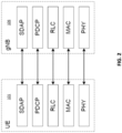
- user and control plane functions with monolithic gNB 106 are shown in the Figure 2 and Figure 3 .
- PHY physical
- MAC Medium Access Control
- RLC Radio Link Control
- PDCP Packet Data Convergence Protocol
- SDAP Service Data Adaptation Protocol
- RRC Radio Resource Control
- PDCP Packet Data Convergence Protocol
- SDAP Service Data Adaptation Protocol
- RRC Radio Resource Control
- PDCP Packet Data Convergence Protocol
- SDAP Service Data Adaptation Protocol
- gNB 106 the network side.
- RRC Radio Resource Control
- PDCP Packet Data Convergence Protocol
- SDAP Service Data Adaptation Protocol
- NAS Non-Access Stratum
- AMF Access Mobility Function
- NG-RAN NG-Radio Access Network
- F1 is the interface between gNB-CU 151 (gNB - Centralized Unit) and gNB-DU 152 (gNB - Distributed Unit)
- NG is the interface between gNB-CU 151 (or gNB) and 5GC (5G Core)
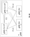
- E1 is the interface between CU-CP (CU-Control Plane) and CU-UP (CU-User Plane)
- Xn is interface between gNBs.
- a gNB 106 may consist of a gNB-CU-CP, multiple gNB-CU-UPs and multiple gNB-DUs.
- the gNB-CU-CP is connected to the gNB-DU 152 through the F1-C interface and to the gNB-CU-UP through the E1 interface.
- the gNB-CU-UP is connected to the gNB-DU 152 through the F1-U interface and to the gNB-CU-CP through the E1 interface.
- One gNB-DU 152 is connected to only one gNB-CU-CP and one gNB-CU-UP is connected to only one gNB-CU-CP.
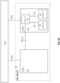
- Figure 4A shows an example of an NG-RAN Architecture as described in 3GPP TS 38.501.
- Figure 4B shows an example of a Separation of CU-CP (CU-Control Plane) and CU-UP (CU-User Plane) as described in 3GPP TS 38.401.
- L2 Layer 2 of 5G NR is split into the following sublayers is described in 3GPP TS 38.300):
- Figure 5 shows a DL (Downlink) Layer 2 Structure as described in 3GPP TS 38.300.
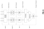
- Figure 6 shows an UL (uplink) Layer 2 Structure in accord with 3GPP TS38.300.
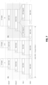
- Figure 7 shows an L2 Data Flow example in accord with 3GPP TS 38.300 ([H] denotes headers or subheaders in Figure 7 .)
- O-RAN which is based on disaggregated components and connected through open and standardized interfaces is based on 3GPP NG-RAN.
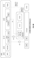
- An overview of O-RAN with disaggregated RAN (CU, DU, and RU), near-real-time RIC 160 and non-real-time RIC is shown in the figure below.
- DU Distributed Unit
- CU Centralized Unit
- COTS Communication off-the-shelf
- Figures 8A-8B show and example of an O-RAN architecture.
- the CU and the DU are connected using the F1 interface (with F1-C for control plane and F1-U for user plane traffic) over the midhaul (MH) path.
- F1 interface with F1-C for control plane and F1-U for user plane traffic
- MH midhaul
- One DU could host multiple cells (for example, one DU could host 24 cells) and each cell may support many users. For example, one cell may support 600 RRC Connected users and out of these 600, there may be 200 Active users (i.e.; users which have data to send at a given point of time).
- a cell site could consist of multiple sectors and each sector may support multiple cells.
- one site could consist of three sectors and each sector could support 8 cells (with 8 cells in each sector on different frequency bands).
- One CU-CP could support multiple DUs and thus multiple cells.
- a CU-CP could support 1000 cells and around 100,000 UEs.
- Each UE could support multiple DRBs and there could be multiple instances of CU-UP to serve these DRBs.
- each UE could support 4 DRBs, and 400,000 DRBs (corresponding to 100,000 UEs) may be served by five CU-UP instances (and one CU-CP instance).
- DU can be located in a private data center or it could be located at a cell-site too.
- CU can also be located in a private data center or even hosted on a public cloud system.
- DU and CU can be tens of kilometers away.
- CU can communicate with 5G core system which could also be hosted in the same public cloud system (or could be hosted by a different cloud provider).
- RU Radio Unit
- FH fronthaul
- the E2 nodes (CU and DU) are connected to the near-real-time RIC 160 using the E2 interface.
- the E2 interface is used to send data (e.g., user, cell, slice KPMs) from the RAN, and deploy control actions and policies to the RAN at near-real-time RIC 160.
- the application or service at the near-real-time RIC 160 that deploys the control actions and policies to the RAN are called xApps.
- the near-real-time RIC 160 is connected to the non-real-time RIC 161 using the A1 interface.
- SMO manages multiple regional networks
- O-RAN NFs O-CUs, Near-RT RIC 160, O-DUs
- SMO Functions and O-RAN NFs are micro services and deployment-independent logical functions
- SMO Functions and O-RAN NFs can be composed of multiple deployment instances deployed in the same O-Cloud or in a different O-Cloud in regional data center, or in cell site according to network requirements (ex. capacity, latency, security, and so on) if the secure connection among SMO Functions and O-RAN NFs are available.
- an O-RAN compliant SMO defines TE&IV, RAN NF OAM, Non-RT RIC, and NFO, FOCOM services.
- SMO interacts with O-RAN NFs with O1 interface.
- SMO interacts with O-RU with Open FH M-Plane interface and interacts O-Cloud via the O2 interface.
- O-RAN NF OAM manages O-RAN NF CM, FM, PM and creates O-RAN NF inventory and topology in TE&IV.
- FOCOM/NFO manages O-Cloud resources and creates O-Cloud resources inventory and topology in TE&IV.
- Analytics/rApp in Non-RT RIC can subscribe O-RAN NFs PM/FM, O-Cloud PM/FM data based on O-RAN NF OAM an FOCOM/NFO.
- Analytics/rApp in Non-RT RIC can retrieve the O-RAN NF and O-Cloud resource inventory and topology.
- PDU connectivity service is a service that provides exchange of PDUs between a UE and a data network identified by a Data Network Name (DNN).
- the PDU Connectivity service is supported via PDU sessions that are established upon request from the UE.
- This DNN defines the interface to a specific external data network.
- One or more QoS flows can be supported in a PDU session. All the packets belonging to a specific QoS flow have the same 5QI (5G QoS Identifier).
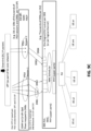
- Figure 9A illustrates a PDU Session architecture consisting of multiple DRBs. Each DRB may consist of multiple QoS flows (3GPP TS 23.501).
- Figure 9B illustrates a flow for PDU sessions, DRBs and GTP-U Tunnels across CU and DU.
- Figure 9C illustrates a CU and DU view on PDU session, DRBs and GTP-U tunnels for a 5G network architecture.
- a PDU session comprises the following: A Data Radio Bearer (DRB) is between UE and CU in RAN and a NG-U GTP tunnel which is between CU and UPF (User Plane Function) in the core network.
- DRB Data Radio Bearer
- UPF User Plane Function
- the transport connection between the base station (i.e., CU-UP) and User Plane Function (UPF) uses a single GTP-U tunnel per PDU session.
- the PDU session is identified using GTP-U TEID (Tunnel Endpoint Identifier).
- the transport connection between DU and CU-UP uses a single GTP-U tunnel per DRB.
- the SDAP (Service Adaptation Protocol) Layer receives downlink data from the UPF across the NG-U interface. It maps one or more QoS Flow(s) onto a specific DRB.
- the SDAP header is present between the UE and the CU (when reflective QoS is enabled), and includes a field to identify the QoS flow within a specific PDU session.
- GTP-U user plane protocol includes a field to identify the QoS flow and is present between CU and UPF (in the core network).
- NR-U NR User Plane
- DBS Desired Buffer Size
- DDR Desired Data Rate
- the NR PDCP hosting node stops sending data for that DRB from the CU-UP to the DU. If value of the DBS is greater than zero, the NR PDCP hosting node (i.e., CU-UP) can send up to this amount of data for that DRB.
- the value of DDR is the amount of data desired to be received every second by the DU (from CU-UP) for that DRB.
- the corresponding node i.e., DU
- the node hosting NR PDCP is CU-UP and the corresponding node is the DU.
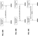
- Figure 10A shows DL User data (i.e., PDCP PDUs) from CU-UP to RLC SDU queues at the DU (corresponding node).
- Figure 10B shows DL Data Delivery Status (DDDS) - Flow Control Feedback from DU to CU-UP (for each DRB).
- Figure 10C shows Radio Assistance Information from DU (corresponding node) to CU-UP.
- Table 1 shows DL Data Delivery Status (DDDS) from the corresponding node (DU) to the node hosting NR PDCP (i.e., CU-UP here) for each DRB.
- DDDS DL Data Delivery Status
- the E-UTRAN comprises of eNBs, providing the E-UTRA U-plane (PDCP/RLC/MAC/PHY) and control plane (RRC) protocol terminations towards the UE.
- the eNBs are interconnected with each other by means of the X2 interface.
- the eNBs are also connected by means of the S1 interface to the EPC (Evolved Packet Core), more specifically to the MME (Mobility Management Entity) by means of the S1-MME interface and to the Serving Gateway (S-GW) by means of the S1-U interface.
- EPC Evolved Packet Core
- MME Mobility Management Entity
- S-GW Serving Gateway
- E-UTRAN also supports MR-DC via E-UTRA-NR Dual Connectivity (EN-DC), in which a UE is connected to one eNB that acts as a MN and one en-gNB 106 that acts as a SN.
- EN-DC E-UTRA-NR Dual Connectivity
- the eNB is connected to the EPC 140 via the S1 interface and to the en-gNB 106 via the X2 interface.
- the en-gNB 106 might also be connected to the EPC 140 via the S1-U interface and other en-gNBs 106 via the X2-U interface.
- EN-DC and en-gNB 106 comprises gNB-CU 151and gNB-DU(s)152.
- NG-RAN node is either:
- the gNBs 106 and ng-eNBs are interconnected with each other by means of the Xn interface.
- the gNBs 106 and ng-eNBs are also connected by means of the NG interfaces to the 5GC, more specifically to the AMF (Access and Mobility Management Function) by means of the NG-C interface and to the UPF (User Plane Function) by means of the NG-U interface.
- AMF Access and Mobility Management Function
- UPF User Plane Function
- the gNB 106 and ng-eNB host functions for Radio Resource Management such as: Radio Bearer Control, Radio Admission Control, Connection Mobility Control, Dynamic allocation of resources to UEs in both uplink and downlink (scheduling), connection setup and release; session Management; QoS Flow management and mapping to data radio bearers; Dual Connectivity.
- Radio Bearer Control Radio Admission Control, Connection Mobility Control, Dynamic allocation of resources to UEs in both uplink and downlink (scheduling), connection setup and release; session Management; QoS Flow management and mapping to data radio bearers; Dual Connectivity.
- control information (e.g., scheduling information) may be provided for broadcast and/or multicast operation.
- the UE may monitor different bundle sizes for the control channel depending on the maximum number of repetitions.
- NSA Non-Standalone
- EN-DC downlink data splitting / routing in the NSA
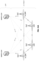
- FIGS 12A-12C show NSA / EN-DC Network Architecture with downlink data splitting.
- 5G Standalone (SA) architectures 5G gNB 106 communicates with 5G Core (and not with 4G Evolved Packet Core 140).
- 4G eNB 116 communicates with 4G Evolved Packet Core (EPC) 140 and not with 5G Core.
- EPC Evolved Packet Core
- the E-UTRA-NR Dual Connectivity is a dominant form of the Non-Standalone (NSA) architecture.
- a 4G eNB (MeNB) as well as 5G gNB (En-gNB) connect with 4G EPC and 5G core is not used in this network architecture.
- the DL (downlink) data goes from 4G EPC 140 to 5G CU-UP 151 where it could be split across two different transmission paths (or network legs): 1) 5G CU-UP 151to 4G DU 142 to NSA UE and 2) 5G CU-UP 151 to 5G DU 152 to NSA UE, and combined again at the NSA UE 101.
- Flow control between CU-UP 151 and DU as specified in the previous section is run 1) between 5G DU 152 and 5G CU-UP 151, and 2) between 4G DU 142 and 5G CU-UP 151 in this architecture.
- Availability of multiple transmission paths between the user plane node in RAN and UE helps to improve transmission reliability, by duplicating the same PDCP PDU on to multiple paths, or increase data rate, by scheduling different data on different paths.
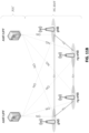
- Figure 12B shows UL Split bearer in NSA Architecture.
- DL data from 4G EPC 140 is first sent to 4G CU-UP 141 where it is split across two transmission paths (or network legs): 1) 4G CU-UP 141 to 4G DU 142 to NSA UE 101 and 2) 4G CU-UP 141 to 5G DU 152 to UE 101, and then combined again at the NSA UE 101.
- uplink data from the UE 101 towards the 5GDU 152/4G DU 142 is split at the UE 101.
- some packets are sent on the 5G leg 154 and other on the 4G leg 144 of the network.
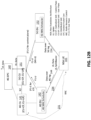
- Figure 12C shows logical architecture for a 5G split bearer.
- DRB Non-Stand Alone
- CU-UP is configured with a scheduling / splitting policy to determine how many PDCP PDUs need to be scheduled onto each of the paths.
- the DRBs carrying these PDCP PDUs from CU-UP can be mapped to RLC Acknowledged Mode (RLC AM), RLC Unacknowledged mode (RLC UM) or RLC Transparent Mode (RLC TM) at the DU.
- RLC AM RLC Acknowledged Mode
- RLC UM RLC Unacknowledged mode
- RLC TM RLC Transparent Mode
- SNs Sequence Numbers
- the CU-UP is further required to configure the splitting policy such that out-of-sequence arrival of PDCP PDUs at the UE is minimized.
- a static policy can be implemented at the CU-UP through "leg-switching" by which the DL PDCP PDUs are scheduled either on the 5G radio interface leg or the 4G interface leg, but not both.
- the radio interface over which data is scheduled can be determined by the radio channel condition of one radio interface (e.g. NR), i.e., data is scheduled i) on NR radio interface if the NR channel performance is above a certain threshold, and ii) on LTE if the NR channel performance is below the threshold.
- This method can be sub-optimal as it only considers NR radio channel condition but not the LTE radio channel condition.
- a dynamic splitting solution according to the present disclosure can be implemented at 5G CU-UP, 5G DU and 4G DU (or other equivalent nodes). Also disclosed is an interleaving approach at CU-UP to minimize PDCP reordering at CU-UP. Also disclosed is a Near-RT RIC-based approach for an exchange of relevant parameters via an E2 interface and a method that can be run at a Near-RT RIC server.
- Example 1 Data routing / splitting when Radio Assistance Information is not available at CU-UP
- An exemplary implementation comprises controlling how much and what data, for instance which PDCP SNs, are transmitted on each of the 4G leg or 5G leg with the help of two methods: a Split Factor Method ("splitFactorMethod") and an SN Schedule Method (“snSchdMethod").
- the trigger for Split Factor Method is the reception of DDDS message at the CU-UP from either the 4G or 5G leg, and the trigger for SN Schedule Method is the presence of any PDCP PDUs in the CU-UP queue.
- a split factor is defined as the pair (X, Y), where X and Y are percentages of the individual PDCP Sequence Numbers (SNs) which are communicated over the 4G and 5G legs.
- a split factor (as part of splitFactorMethod) specifies the number of bytes which are to be transmitted on each leg, and not the actual identity of PDCP PDU SNs associated with the data.
- the second method, SN Schedule Method decides the sequence of PDCP SNs to be scheduled on each leg.
- Table 2 shows DDDS parameters and intermediate factors that are used by the splitting method to compute the final splitting factor .
- Table 2 Parameter in DDDS communicated from DU to CU-UP for a DRB Intermediate factors used in the computation of the final splitting factor Desired buffer size (DBS) for the data radio bearer dbsFactorLTE for LTE leg, dbsFactorNR for NR leg, Desired Data Rate (DDR) ddrFactorLTE for LTE leg, ddrFactorNR for NR leg Number of lost NR-U Sequence Number ranges reported, Start of lost NR-U Sequence Number range, End of lost NR-U Sequence Number range; MHQualitvFactorLTE for LTE leg, MHQualityFcatorNR for NR leg Highest successfully delivered NR PDCP Sequence Number, Highest transmitted NR PDCP Sequence Number; Successfully delivered retransmitted NR PDCP Sequence Number, Retransmitted NR PDCP Sequence Number quality
- WDbs is the weight assigned to above factor and m is a scaling constant (such as 100).
- dbsFactorNR m * WDbs * (DBS indicated by NR DU) / (DBS indicated by LTE DU + DBS indicated by NR DU)
- the DBS weight (WDbs) is the weight expressed in range 0-1, and is the weightage given to either a "dbsFactorLTE" or a "dbsFactorNR" in contribution to the overall split factor defined as "SplitFactorLTE" and "SplitFactorNR" below.
- DDR Factor computations are configured to operate on the received DDR on the respective leg. If DDR is present in DDDS, the intermediate factor ddrFactorLTE or ddrFactorNR is computed as the ratio of DDR received in the respective leg to the sum of the latest DDRs received in DDDS from both the legs.
- WDdr is the weight expressed in range 0-1, is the weightage given to either "ddrFactorLTE" or "ddrFactorNR" in contribution to the overall split factor below.
- ddrFactorNR m * (Wddr) * (DDR received from the SgNB.DU)/((DDR received from SgNB.DU+ DDR as received from MeNB.DU) ). If DDR was not received from MeNB.DU then the component "DDR as received from MeNB.DU in the previous DDDS message" is considered as 0, in the denominator.
- CU-UP computations employ various other parameters (from DDDS) as shown below to determine the quality of midhaul (i.e., midhaul between 5G CU-UP and 5G DU, and between 5G CU-UP and 4G DU) and the quality of each leg (i.e., 5G CU-UP - 4G DU - (air-interface) - UE, and 5G CU-UP - 5G DU - (air-interface) - UE).
- midhaul i.e., midhaul between 5G CU-UP and 5G DU, and between 5G CU-UP and 4G DU
- each leg i.e., 5G CU-UP - 4G DU - (air-interface) - UE, and 5G CU-UP - 5G DU - (air-interface) - UE).
- Parameters from DDDS messages employed to determine the quality of midhaul include the Number of lost NR-U Sequence Number ranges reported. Parameters also include start of lost NR-U Sequence Number range and end of lost NR-U Sequence Number range. With these and other DDDS parameters, the percentage of packets getting lost over each midhaul interface can be estimated (i.e., between 5G CU-UP and 5G DU, and between 5G CU-UP and 4G DU).
- Parameters from DDDS messages employed to determine quality of each leg include:
- SgNB.CUUP transmits all the packets which have not been acknowledged from the leg reporting Radio Link Outage to the surviving leg. This can cause a few duplicate DL PDCP Packets at the UE side. However, those packets can be discarded based on the PDCP SNs at the UE. Additionally, based on the "Highest successfully delivered NR PDCP Sequence Number" (RLC AM) or "Highest transmitted NR PDCP Sequence Number" (RLC UM), SgNB.CUUP can decide which PDCP SNs are received successfully at UE, and thus can exclude those SNs while transmitting them on the surviving leg.
- a final split factor is maintained per leg separately. It is computed whenever the intermediate factors are re-evaluated as explained in the above steps.
- the sum of all intermediate factors of a given leg “I" (leg-i) is denoted as Li.
- "i" takes values "LTE” and "5G NR”.
- a total sum of all intermediate factors of both legs is denoted as L.
- Example 2 Data routing when Radio Assistance Information is available at CU-UP
- the radio assistance information provides the following characteristics about the DU-UE link to the CU-UP: Average CQI, Average HARQ Failure, Average HARQ Retransmissions, DL Radio Quality Index, UL Radio Quality Index, and Power Headroom Report as per 3GPP TS 38.425.
- Routing Metric MCSrate AverageCQI ⁇ DL Radio Quality Index 100 ⁇ F 1 HARQ Failure ⁇ F 2 PL , UL Radio Quality Index
- MCSRate is a function mapping average CQI to data rate It is based either on DDR reported or a predefined formula. Other factors like load of DU and BW (bandwidth) of link are also considered. If one uses DDR, it maps the Average CQI to a DDR value reported by the DU with lower or higher value of CQI resulting in a scaled value based on DDR. For example, for a UE average CQI of 7 is mapped to DDR value of 10 Mbps by MCSRate function. After a certain time, if the average CQI reported by DU is 15 then the MCSRate function maps it to a throughput of 25 Mbps.
- F1(HARQ Failure) is a function that maps HARQ Failure rate to appropriate weightage factor.
- the function can be defined as such that if HARQ failure is below a threshold (e.g.: 10%/15%), the value of function becomes 1; if the HARQ failure rate is higher than that the value of function reduces to zero.
- F2 (PL, UL Radio Quality Index) is a weightage function for path loss (PL) derived from Power Headroom reports and UL Radio link quality index. This function works in the following way.
- this function takes value 1, implying UL can carry all the ACKs generated by RLC or higher layers. If the PL is above the threshold, this function decreases gradually to 0. This function signifies the capacity of UL link to carry a fraction of UL acknowledgements. This is considered for TCP kind of traffic where ACK is transmitted in reverse direction, and AM traffic bearers are used where RLC status PDUs are transmitted in the reverse direction. For UDP Traffic with UM bearer, value of this function is always 1.
- Routing Metric is a measure of throughput the link can provide. Routing metrics of the two links are compared (between MeNB (4G) link and SgNB (5G) link), and CU-UP split the data based on their ratio.
- CU-UP will combine this metric with other metrics, e.g., SplitFactorLTE and SplitFactorNR given in Example 1, or DBS and DDR with suitable weightage factor, to deciding the splitting factor across the different links.
- this computation is done in the RIC, where the RIC can combine this data with other data directly available from different DU, e.g., load information, number of active users, and bandwidth (BW), to determine the optimal split factor.
- Example 3 Routing and splitting at CU-UP to achieve in-sequence delivery at UE
- Splitting refers to deciding which PDCP SNs are to be transmitted on which transmission path.
- One consideration while splitting PDCP PDUs across LTE and NR transmission paths is to ensure that PDCP Sequence Numbers (SNs) arrive at UE in-sequence. Any out-of-order PDCP PDU arrival at UE triggers a reordering timer, followed by out-of-order delivery of PDCP PDUs to the higher layer upon timer expiry, leading to performance degradation.
- the CU-UP is configured ensure that it splits (i.e., interleaves) PDCP SNs among the two paths in such a way that reordering is minimized at the UE.
- the design of a splitting method hinges on the CU-UP's ability to estimate one-way delays for each of the two transmission paths, where one-way delay for a given transmission path in DL is the delay from the time a PDCP PDU is transmitted on the path in question to the time it reaches the PDCP layer at UE.
- 3GPP TS 28.552 has standardized various RAN parts of DL packet delay measurements as follows:
- DU can communicate the delay component 1) in the ASSISTANCE INFORMATION DATA PDU to CU-UP (the field DL Delay DU Result).
- the delay counters 3) and 4) are computed in the CU-UP itself.
- two exemplary methods by which the delay counter 2) can be conveyed to CU-UP are described below.
- Exemplary Method 3A Disclosed is an implementation for the ASSISTANCE INFORMATION DATA PDU by defining a new field "DL Delay in DU” which carries the counter "DL delay on gNB-DU” (see, e.g., Table 2).
- the description of the field is as follows.
- a DL Delay in DU field indicates a delay measured in DL at the corresponding node in milliseconds for the concerned DRB in the RLC layer. It is encoded as an Unsigned 32 binary integer value.
- the node hosting PDCP entity if supported, is configured to use this information to calculate the one-way delay in DL for the concerned DRB from CU-UP to UE's PDCP layer.
- Exemplary Method 3B Another example implementation for conveying DL delay in RLC layer to CU-UP is through CU-CP. That is, DU first communicates this delay to CU-CP over the F1-C interface followed by CU-CP relaying the same information over the E1 interface to CU-UP.
- This implementation requires F1-C and E1 interface messages be either appropriately modified or new messages be defined.
- the UE CONTEXT SETUP REQUEST and UE CONTEXT MODIFICATION REQUEST messages by including the Boolean parameter "RLC Delay Required” and "Periodicity for RLC Delay" for all the SRB/DRB for which RLC delay in DU is sought.
- the range for the parameter Periodicity for RLC Delay can be from 0 to 255 ms.
- the UE CONTEXT SETUP RESPONSE and UE CONTEXT MODIFICATION RESPONSE includes the Boolean variable "RLC Delay Inclusion".
- TRUE means DU can provide this information at the requested periodicity "Periodicity for RLC Delay".
- a F1-C message "DRB Stats" is defined and added, which includes the UE gNB-CU UE F1AP ID, gNB-DU UE F1AP ID and RLC Delay for as many DRBs for which DU agreed to send RLC delay information.
- Implementations for the E1 interface To have CU-CP relay the information carried in the DRB Stats F1-C message to CU-UP, the E1 interface includes an E1 message "F1-C CONTAINER", which encapsulates the "DRB Stats" message of the F1-C interface with appropriate meta information so that CU-UP knows which DRB of which UE the information is related to.
- CU-UP can estimate one-way delay in the DL across the 4G leg as well as the 5G leg.
- the splitting method at the CU-UP considers the delay over the 4G and 5G legs, and interleaves packets (based on their sequence numbers) when sending to the UE so that most of the packets arrive in-order at the UE.
- the longer network leg is defined to be that transmission path which has larger one-way-delay compared to the other transmission path.
- shorter network leg is defined to be that transmission path which has smaller one-way-delay compared to the other transmission path.
- t i and t j are defined to be the time-instants at which PDCP PDUs with SNs i and j are transmitted.
- In-sequence delivery at UE's PDCP requires that t i + (one-way delay on the longer-leg) ⁇ (t j + one-way delay on the shorter-leg).
- any SN j > i can be transmitted on the shorter-leg only after a delay of ⁇ to ensure that SNs i and j arrive in-sequence at UE.
- PDCP SNs are scheduled on the two paths alternatively, i.e., SNs 1, 3, 5, 7, ... on one path and SNs 2, 4, 6, 8, ... on the other path.
- Transmission for SN 2 can start after a delay equal to (processing delay + transmission time + ⁇ ).
- Methods 3A and 3B described above work effectively when the splitting method is defined in CU-UP.
- the splitting method can be also implemented in the RIC.
- the 3GPP-defined and O-RAN-compliant logical nodes O-CP, O-UP, and O-DU communicate with RIC via the E2 interface.
- the messages defined under Methods 3A and 3B can communicate the DL delay in RLC layer to O-UP, can also be added for the E2 interface.
- Example 4 RIC based data routing decisions for downlink split bearer
- CU-UP may not be able to handle the additional need of computational power for the dynamic splitting decision making methods. Under such circumstances, in an implementation, CU-UP can offload this processing to the RIC over the E2 interface.
- the RIC can make the intelligent decisions on the dynamic splitting and convey the dynamic splitting policies for the concerned bearer(s) towards CU-UP for the latter to apply, for the next defined T durations and/or for the next P packets towards either of the legs.
- an operator may want to use CU/DU from a first vendor X, but do the decision-making for the splitting as provided by vendor Y. In this case, one can offload the splitting decision at the RIC and run the solution provided by vendor Y there.
- SgNB.CUUP can communicate the relevant parameters to RIC over the E2 interface.
- the RIC performs the analysis, and the results are fed back to CU-UP.
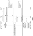
- An implementation of the method for data routing in NSA architecture is described below with respect Figure 15.
- the subscription procedure is triggered with RIC.
- the MeNB sends DDDS and Assisted Radio Information respectively to SgNB-CUUP.
- the SgNB.DU MeNB send DDDS and Assisted Radio Information respectively to SgNB-CUUP.
- SgNB.CUUP registers the DDDS and Assisted Radio Information procedure as event triggers in RIC. With this, whenever DDDS and Assisted Radio Information are received from either MeNB or from SgNB.DU, at block 308, this triggers an event towards RIC.
- RIC Indication(Insert) On reception of DDDS and/or Assistance Information data at SgNB.CUUP, either from MeNB or SgNB.DU, when the messages are received at SgNB.CUUP from either of the legs, at block 308, the message "RIC Indication(Insert)" is triggered towards Near-RT-RIC. At block 310 RIC processes the message and decides the policies to be applied to either or both of the legs. It can use one or more of the exemplary methods tdescribed in the previous sections.
- the example policies can be, e.g.:
- the RIC sends "RIC control request" to SgNB.CUUP.
- gNB.CUUP can respectively apply the policies on MeNB, SgNB, or both, depending on the indication received in "RIC Control Request”.
- implementations and embodiments can be implemented by computer program instructions. These program instructions can be provided to a processor to produce a machine, such that the instructions, which execute on the processor, create means for implementing the actions specified herein.
- the computer program instructions can be executed by a processor to cause a series of operational steps to be performed by the processor to produce a computer-implemented process such that the instructions, which execute on the processor to provide steps for implementing the actions specified.
- some of the steps can also be performed across more than one processor, such as might arise in a multi-processor computer system or even a group of multiple computer systems.
- one or more blocks or combinations of blocks in the flowchart illustration can also be performed concurrently with other blocks or combinations of blocks, or even in a different sequence than illustrated without departing from the scope or spirit of the invention.
Landscapes
- Engineering & Computer Science (AREA)
- Computer Networks & Wireless Communication (AREA)
- Signal Processing (AREA)
- Mobile Radio Communication Systems (AREA)
Applications Claiming Priority (2)
| Application Number | Priority Date | Filing Date | Title |
|---|---|---|---|
| IN202321030170 | 2023-04-26 | ||
| US18/644,203 US20240365321A1 (en) | 2023-04-26 | 2024-04-24 | Method and system for data routing for split-bearer at a cellular base station for a dual connectivity network architecture |
Publications (2)
| Publication Number | Publication Date |
|---|---|
| EP4456602A2 true EP4456602A2 (fr) | 2024-10-30 |
| EP4456602A3 EP4456602A3 (fr) | 2024-12-11 |
Family
ID=90922653
Family Applications (1)
| Application Number | Title | Priority Date | Filing Date |
|---|---|---|---|
| EP24172759.3A Pending EP4456602A3 (fr) | 2023-04-26 | 2024-04-26 | Procédé et système de routage de données pour un utilisateur à partage de ressources au niveau d'une station de base cellulaire pour une architecture de réseau à double connectivité |
Country Status (1)
| Country | Link |
|---|---|
| EP (1) | EP4456602A3 (fr) |
Family Cites Families (5)
| Publication number | Priority date | Publication date | Assignee | Title |
|---|---|---|---|---|
| CN112187414B (zh) * | 2019-07-04 | 2022-05-24 | 华为技术有限公司 | 指示数据传输情况的方法和装置 |
| EP3869847B1 (fr) * | 2020-02-24 | 2024-01-10 | INTEL Corporation | Gestion de trafic multi-accès dans ran ouvert, o-ran |
| EP3886383A1 (fr) * | 2020-03-23 | 2021-09-29 | Nokia Solutions and Networks Oy | Appareil, procédé et programme informatique pour l'acheminement de données dans une configuration à double ou multi-connectivité |
| US11291080B2 (en) * | 2020-04-30 | 2022-03-29 | Apple Inc. | Link quality reporting enhancements for new radio |
| US12192820B2 (en) * | 2021-03-22 | 2025-01-07 | Intel Corporation | Reinforcement learning for multi-access traffic management |
-
2024
- 2024-04-26 EP EP24172759.3A patent/EP4456602A3/fr active Pending
Also Published As
| Publication number | Publication date |
|---|---|
| EP4456602A3 (fr) | 2024-12-11 |
Similar Documents
| Publication | Publication Date | Title |
|---|---|---|
| KR102941072B1 (ko) | 근접 기반 서비스 원격 및 중계 엔티티 서비스 품질 관리 | |
| US12089276B2 (en) | Alternate path information exchange for better scheduling and backhaul failure recovery in integrated access backhaul networks | |
| EP3295700B9 (fr) | Division de données de liaison montante | |
| JP6920417B2 (ja) | 動的リンク選択 | |
| US20200187282A1 (en) | Control Mechanism for Packet Duplication in Multi-Connectivity Communication | |
| WO2024039898A1 (fr) | Procédé et appareil permettant de mettre en œuvre une intelligence ia-un apprentissage ml dans un réseau sans fil | |
| WO2019059836A1 (fr) | Procédés et unités dans un nœud de réseau destiné au traitement d'une communication avec un dispositif sans fil | |
| KR20190129191A (ko) | 차세대 이동 통신 시스템에서 주변 셀의 기준 신호로 준지속적 사운딩 기준 신호를 지시하는 방법 및 장치 | |
| US20210328699A1 (en) | Communications Method and Apparatus | |
| WO2017216510A1 (fr) | Fourniture d'une description de flux de données de service | |
| US20240365321A1 (en) | Method and system for data routing for split-bearer at a cellular base station for a dual connectivity network architecture | |
| US11646835B2 (en) | Transmission of a packet data convergence protocol (PDCP) protocol data unit (PDU) in a wireless communication network | |
| EP4241491A1 (fr) | Procédés et noeuds de réseau pour gérer une congestion associée à un plan de commande | |
| EP4456602A2 (fr) | Procédé et système de routage de données pour un utilisateur à partage de ressources au niveau d'une station de base cellulaire pour une architecture de réseau à double connectivité | |
| US20240365170A1 (en) | Method and system smart high availability system for embb/urllc combinations | |
| EP4472344A2 (fr) | Systèmes et procédés pour optimisations de commande de flux d'unité distribuée ou d'unité centralisée pour systèmes cellulaires hautement extensibles | |
| US20240381174A1 (en) | Systems and methods for distributed unit or centralized unit flow control optimizations for highly scalable cellular systems | |
| US20240365166A1 (en) | Method and system for managing an uplink split bearer | |
| WO2025245780A1 (fr) | Architecture commune d'un cu-up pour un réseau d'accès radio | |
| EP4456601A1 (fr) | Procédé et système de gestion d'un support divisé de liaison montante | |
| EP4460065A1 (fr) | Procédé de réduction d'interférence intercellulaire dans des réseaux cellulaires | |
| EP4462926A1 (fr) | Système et procédé pour régler une capacité pucch | |
| WO2017028681A1 (fr) | Procédés et dispositifs de rapport d'état de transmission de données et de détermination de volume de transmission de données | |
| WO2026044014A1 (fr) | Transmission de signal de référence de gestion de brouillage à distance | |
| EP4456515A1 (fr) | Procédé et système intelligent à haute disponibilité pour combinaisons embb/urllc |
Legal Events
| Date | Code | Title | Description |
|---|---|---|---|
| PUAI | Public reference made under article 153(3) epc to a published international application that has entered the european phase |
Free format text: ORIGINAL CODE: 0009012 |
|
| STAA | Information on the status of an ep patent application or granted ep patent |
Free format text: STATUS: REQUEST FOR EXAMINATION WAS MADE |
|
| 17P | Request for examination filed |
Effective date: 20240426 |
|
| AK | Designated contracting states |
Kind code of ref document: A2 Designated state(s): AL AT BE BG CH CY CZ DE DK EE ES FI FR GB GR HR HU IE IS IT LI LT LU LV MC ME MK MT NL NO PL PT RO RS SE SI SK SM TR |
|
| PUAL | Search report despatched |
Free format text: ORIGINAL CODE: 0009013 |
|
| AK | Designated contracting states |
Kind code of ref document: A3 Designated state(s): AL AT BE BG CH CY CZ DE DK EE ES FI FR GB GR HR HU IE IS IT LI LT LU LV MC ME MK MT NL NO PL PT RO RS SE SI SK SM TR |
|
| RIC1 | Information provided on ipc code assigned before grant |
Ipc: H04W 28/08 20230101AFI20241105BHEP |