EP4458272A1 - Aiguille de ponction - Google Patents
Aiguille de ponction Download PDFInfo
- Publication number
- EP4458272A1 EP4458272A1 EP23740311.8A EP23740311A EP4458272A1 EP 4458272 A1 EP4458272 A1 EP 4458272A1 EP 23740311 A EP23740311 A EP 23740311A EP 4458272 A1 EP4458272 A1 EP 4458272A1
- Authority
- EP
- European Patent Office
- Prior art keywords
- distal
- main body
- side wall
- puncture needle
- recess
- Prior art date
- Legal status (The legal status is an assumption and is not a legal conclusion. Google has not performed a legal analysis and makes no representation as to the accuracy of the status listed.)
- Pending
Links
Images






Classifications
-
- A—HUMAN NECESSITIES
- A61—MEDICAL OR VETERINARY SCIENCE; HYGIENE
- A61B—DIAGNOSIS; SURGERY; IDENTIFICATION
- A61B17/00—Surgical instruments, devices or methods
- A61B17/34—Trocars; Puncturing needles
-
- A—HUMAN NECESSITIES
- A61—MEDICAL OR VETERINARY SCIENCE; HYGIENE
- A61B—DIAGNOSIS; SURGERY; IDENTIFICATION
- A61B17/00—Surgical instruments, devices or methods
- A61B17/34—Trocars; Puncturing needles
- A61B17/3403—Needle locating or guiding means
-
- A—HUMAN NECESSITIES
- A61—MEDICAL OR VETERINARY SCIENCE; HYGIENE
- A61B—DIAGNOSIS; SURGERY; IDENTIFICATION
- A61B17/00—Surgical instruments, devices or methods
- A61B17/34—Trocars; Puncturing needles
- A61B17/3417—Details of tips or shafts, e.g. grooves, expandable, bendable; Multiple coaxial sliding cannulas, e.g. for dilating
-
- A—HUMAN NECESSITIES
- A61—MEDICAL OR VETERINARY SCIENCE; HYGIENE
- A61B—DIAGNOSIS; SURGERY; IDENTIFICATION
- A61B17/00—Surgical instruments, devices or methods
- A61B17/34—Trocars; Puncturing needles
- A61B17/3403—Needle locating or guiding means
- A61B2017/3413—Needle locating or guiding means guided by ultrasound
-
- A—HUMAN NECESSITIES
- A61—MEDICAL OR VETERINARY SCIENCE; HYGIENE
- A61B—DIAGNOSIS; SURGERY; IDENTIFICATION
- A61B8/00—Diagnosis using ultrasonic, sonic or infrasonic waves
- A61B8/08—Clinical applications
- A61B8/0833—Clinical applications involving detecting or locating foreign bodies or organic structures
- A61B8/0841—Clinical applications involving detecting or locating foreign bodies or organic structures for locating instruments
Definitions
- the present disclosure relates to a puncture needle.
- Patent Literature 1 JP H3-228748 A discloses an ultrasound reflector including a needle or a pipe inserted into an object while confirming an image of a deep portion in an ultrasound guide, the needle or the pipe having an insertion portion whose surface is formed uneven.
- the ultrasound reflector one having a V-groove formed on a surface of an outer needle is described.
- the V-groove has a groove angle of around 90°, and as the V-groove, one formed such that each of two sides has 45° with respect to the surface of the outer needle and one having one side having an angle smaller than 45° and the other side having an angle larger than 45° are described.
- Patent Literature 2 JP 2019-208962 A (Patent Literature 2) describes a follicular growth inducing device.
- the follicular growth inducing device includes: an ovarian puncture needle that forms a puncture hole by puncturing an ovary in a traveling direction of ultrasound emitted from a probe in a transvaginal ultrasound device toward the ovary; an optical fiber that guides a laser beam emitted from a laser generator; a guide being tubular to receive a needle tube of the ovarian puncture needle; and a fastener that fastens the guide to the probe.
- the guide is fastened to the probe in a manner elongated in the traveling direction of the ultrasound toward the ovary.
- Patent Literature 1 there is a case where a structure that reflects ultrasound is formed on an outer surface of a puncture needle in consideration of echo visibility regarding puncture under an echo.
- Patent Literature 2 there is room for improvement in the echo visibility in a case where puncture is performed in the traveling direction of the ultrasound using the puncture needle as described in Patent Literature 2, that is, in a case where a procedure is performed in a state where the probe of an ultrasound diagnostic device is brought into contact in a direction along an axial direction of the puncture needle from a proximal side of the puncture needle.
- the present disclosure has been made in view of such reality, and an object thereof is to provide a puncture needle with improved echo visibility in a state where a probe of an ultrasound diagnostic device is brought into contact in a direction along an axial direction of the puncture needle from a proximal side of the puncture needle.
- a puncture needle includes: a main body having a rod shape; a needle tip formed at a distal portion of the main body; and a recess formed in a side portion of the main body, wherein the recess has a distal-side wall that has a wall surface facing a proximal side and facing a direction of being warped at 0° or more and 75° or less from a direction along an axis of the main body to a radially outer side of the main body, and the distal-side wall and the main body are separated from each other when viewed in a normal direction of the distal-side wall.
- the distal-side wall is directed in a direction of being warped to the radially outer side of the main body from an orientation directly facing the back on the proximal side.
- a virtual line connecting a bottom-side end of the distal-side wall and a proximal end of the recess in the direction along the axis intersects the distal-side wall at an obtuse angle.
- the recess has the distal-side wall having a planar shape and a proximal-side wall that has a planar shape and extends from the bottom-side end of the distal-side wall to the proximal end of the recess, and the proximal-side wall is formed along the virtual line.
- the recess is formed in the needle tip.
- the needle tip has a blade surface obtained by cutting a distal portion of the main body obliquely with respect to the direction along the axis, and the recess is disposed at the same position as the blade surface in the direction along the axis.
- the puncture needle with the improved echo visibility in the state where the probe of the ultrasound diagnostic device is brought into contact in the direction along the axial direction of the puncture needle from the proximal side of the puncture needle.
- a puncture needle according to an embodiment of the present disclosure is described with reference to the drawings.
- a puncture needle 100 includes a main body 1 having a rod shape, a needle tip 2 formed at a distal portion of the main body 1, and a recess 3 formed in a side portion of the main body 1. Note that Fig. 1 is a side view of the puncture needle 100.
- the recess 3 has a distal-side wall 31 having a wall surface facing a proximal side and facing a direction of being warped at 0° or more and 75° or less from a direction along an axis G of the main body 1 to the radially outer side of the main body 1.
- the distal-side wall 31 and the main body 1 (a boundary 3a to be described later) on the proximal side of the recess 3 are separated from each other (see Fig. 3 ).
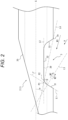
- Fig. 2 is a partially enlarged view illustrating the vicinity of the recess 3 in Fig. 1 in an enlarged manner.
- Fig. 3 is a view in which the recess 3 is viewed in the normal direction of the distal-side wall 31, that is, the recess 3 is viewed in a direction of an arrow A in Fig. 2 .
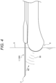
- the puncture needle 100 is suitable for a procedure in a state where a probe 9 of an ultrasound diagnostic device is brought into contact with a body surface H of a living body in the direction along the axis G of the main body 1 of the puncture needle 100 from the proximal side of the puncture needle 100.
- the puncture needle 100 has improved echo visibility as will be described later.
- the main body 1 has a cylindrical tubular shape as an example of the rod shape.
- a space defined by an inner wall 10 of the tubular inside of the main body 1 is a lumen S.
- the main body 1 may be made of, for example, a metal such as stainless steel, titanium, a titanium alloy, or a cobalt-chromium alloy or a synthetic resin such as a fluororesin or a polyolefin resin.
- a metal such as stainless steel, titanium, a titanium alloy, or a cobalt-chromium alloy
- a synthetic resin such as a fluororesin or a polyolefin resin.
- a case where the main body 1 is made of stainless steel is exemplified.
- the needle tip 2 is formed at a distal end of the main body 1.
- the needle tip 2 has, for example, a shape having a blade surface 20 obtained by cutting the distal portion of the main body 1 obliquely with respect to the direction along the axis G.
- the needle tip 2 may have a shape other than the shape having the blade surface 20 obtained by obliquely cutting the distal portion of the main body 1.
- the lumen S is a space continuously formed along the axis G inside the main body 1.
- the lumen S is formed as a cylindrical space whose axis overlaps the axis G and whose cross section orthogonal to the axis G has a circular shape.
- a case where the lumen S communicates with an external space via an opening 20s formed in the blade surface 20 is exemplified.
- the recess 3 is formed in the side portion of the main body 1.
- the recess 3 is recessed in a direction intersecting the axis G.
- the recess 3 may be formed in a trapezoidal shape, a V-shape, or the like in which the radially outer side of the main body 1 is widened in the direction along the axis G in the side view of the puncture needle 100.
- Figs. 1 and 2 illustrate a case where the recess 3 is formed in the trapezoidal shape.
- the recess 3 is formed in a range from an outer peripheral surface of the main body 1 to reach the lumen S, and an opening 39 communicating with the lumen S is formed in the recess 3.
- Fig. 5 is a top view of the vicinity of the recess 3 in the puncture needle 100, and is a view of the puncture needle 100 in the state illustrated in Figs. 1 and 2 as viewed from the bottom to the top in Fig. 1 .
- the recess 3 is formed in the needle tip 2 in the present embodiment. That is, the recess 3 is disposed at the same position as the needle tip 2 in the direction along the axis G. When description is made in relation to the blade surface 20, the recess 3 is disposed at the same position as the blade surface 20 in the direction along the axis G. As a result, the visibility under an echo of the needle tip 2 is improved.
- the recess 3 is preferably formed in the main body 1 on the opposite side of the blade surface 20 with respect to the axis G.
- the recess 3 includes a bottom wall 32 serving as a bottom surface, the distal-side wall 31 which is located on a distal side of the bottom wall 32 and extends from the outer peripheral surface of the main body 1 to the bottom wall 32, and a proximal-side wall 33 which is located on the proximal side of the bottom wall 32 and extends from the outer peripheral surface of the main body 1 to the bottom wall 32.
- the bottom wall 32 has a planar bottom surface along the axis G.
- the opening 39 (see Fig. 3 ) communicating with the lumen S is formed in the bottom wall 32.
- the opening 39 may be used as a so-called back eye in the puncture needle 100.
- the distal-side wall 31 is a planar wall that is the outer peripheral surface of the main body 1 and extends from a distal end of the recess 3 to the bottom wall 32.
- the planar portion of the distal-side wall 31 is slightly inclined to the radially outer side of the main body 1 from an orientation facing the proximal side in the direction along the axis G. That is, the distal-side wall 31 is directed in a direction of being warped to the radially outer side of the main body 1 from an orientation directly facing the back on the proximal side of the main body 1.
- the proximal-side wall 33 is a planar wall which is the outer peripheral surface of the main body 1 and extends from a proximal end of the recess 3 to the bottom wall 32.
- the planar portion of the proximal-side wall 33 is slightly inclined to the radially outer side of the main body 1 from an orientation facing the distal side in the direction along the axis G. That is, the proximal-side wall 33 is directed in a direction of being warped to the radially outer side of the main body 1 from an orientation directly facing the front on the distal side of the main body 1.
- a virtual line along the wall surface of the distal-side wall 31, the line intersecting the axis G is illustrated as a virtual line L1 in a side view (a side view in a state illustrated in Fig. 2 in the present embodiment, referred to as a predetermined side view hereinafter) in a case where the puncture needle 100 is viewed from a predetermined circumferential position with respect to the axis G (the main body 1).
- the predetermined side view in the present embodiment is a viewpoint of viewing the recess 3 from a side surface.
- a virtual line along a wall surface of the bottom wall 32 is illustrated as a virtual line L2.
- the planar portion of the wall surface of the distal-side wall 31 overlapping the virtual line L1 is directed in the direction of being warped to the radially outer side of the main body 1 from the orientation facing the proximal side, that is, the orientation directly facing the back.
- the distal-side wall 31 can reflect ultrasound W1 from the probe 9 to the proximal side as a reflected wave W2.
- a virtual line along a normal line of the virtual line L1, that is, the distal-side wall 31, is illustrated as a virtual line L3.
- an angle at which the virtual line L1 intersects the axis G is indicated by an intersection angle ⁇ , and the intersection angle ⁇ is 15° or more and 90° or less. That is, the distal-side wall 31 intersects the axis G at the angle of 15° or more and 90° or less.
- an angle at which the virtual line L3 along the normal line of the virtual line L1 (the distal-side wall 31) intersects the axis G is indicated by an intersection angle ⁇ . That is, the virtual line L3 along the normal line of the virtual line L1 intersects the axis G at 0° or more and 75° or less.
- the distal-side wall 31 overlapping the virtual line L1 is directed toward the orientation directly facing the back on the proximal side and in the direction of being warped at 0° or more and 75° or less from the direction along the axis G to the radially outer side of the main body 1.
- the bottom-side end of the distal-side wall 31 is a boundary position between the distal-side wall 31 and the bottom wall 32.
- a case where a boundary portion between the distal-side wall 31 and the bottom wall 32 is formed in a curved surface shape is illustrated in the present embodiment.
- a position P2 where a virtual line (the same as the virtual line L4 in the present embodiment) connecting the boundary 3a and an intersection P1 between the virtual line L2 and the virtual line L1 intersects the boundary portion between the distal-side wall 31 and the bottom wall 32 is defined as the boundary position between the distal-side wall 31 and the bottom wall 32.
- an angle at which the virtual line L4 intersects the virtual line L1 is indicated by an intersection angle ⁇ . That is, the intersection angle ⁇ is the obtuse angle (more than 90° and less than 180°).
- the intersection angle ⁇ is the obtuse angle (more than 90° and less than 180°).
- intersection angle ⁇ is preferably more than 120° and less than 170°.
- the echo visibility of the puncture needle 100 can be improved even if the probe 9 slightly deviates from the direction along the axis G of the puncture needle 100 from the proximal side of the puncture needle 100 under an echo in a generally assumed procedure.
- the distal-side wall 31 is formed in the planar shape, the ultrasound W1 incident on the distal-side wall 31 is reflected without being diffused. Therefore, the reflected wave W2 is reflected with large energy toward the proximal side. As a result, it is possible to further improve the echo visibility of the puncture needle 100 in the state where the probe 9 (see Fig. 4 ) of the ultrasound diagnostic device is brought into contact in the direction along the axis G of the puncture needle 100 from the proximal side of the puncture needle 100.
- the distal-side wall 31 may be formed in a curved surface shape. The distal-side wall 31 formed in the curved surface shape can reflect the ultrasound W1 incident at a plurality of angles (various angles).
- the recess 3 is not limited to the trapezoidal shape.
- the recess 3 does not necessarily penetrate to the lumen S.
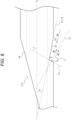
- Fig. 6 is an enlarged view of the vicinity of the recess 3 in a case where the recess 3 does not penetrate to the lumen S. In this manner, the recess 3 does not necessarily penetrate to the lumen S.
- Figs. 7 and 8 illustrate a case where the recess 3 has a V-shape in a side view of the main body 1.
- the recess 3 is formed of the distal-side wall 31 having a planar shape and the proximal-side wall 33 having a planar shape.
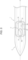
- Fig. 9 illustrates a top view of the vicinity of the recess 3. That is, Fig. 9 is a view of the puncture needle 100 in a state illustrated in Figs. 7 and 8 as viewed from the bottom to the top in Fig. 1 .
- the above-described bottom wall 32 (see Fig. 2 and the like) is flush with the proximal-side wall 33.
- the description is made considering that the proximal-side wall 33 includes the above-described bottom wall 32.
- the above-described virtual line L2 (see Fig. 2 ) is treated as a line along the proximal-side wall 33.
- the bottom-side end of the distal-side wall 31 is connected to a bottom-side end of the proximal-side wall 33.
- the proximal-side wall 33 is formed as a planar wall extending from the bottom-side end of the distal-side wall 31 to a proximal end of the recess 3.
- the proximal-side wall 33 preferably overlaps the virtual line L4 connecting the boundary 3a between the proximal-side wall 33 and an outer surface of the main body 1 and the bottom-side end of the distal-side wall 31.
- a plurality of the recesses 3 may be formed in the main body 1. Therefore, it is possible to further improve the echo visibility of the puncture needle 100 in the state where the probe 9 (see Fig. 4 ) of the ultrasound diagnostic device of the ultrasound diagnostic device is brought into contact in the direction along the axis G of the puncture needle 100 from the proximal side of the puncture needle 100.
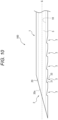
- At least one of the plurality of recesses 3 may be disposed at the same position as the needle tip 2 (in Fig. 10 , the blade surface 20) in the direction along the axis G. As a result, the visibility under an echo of the needle tip 2 is improved.
- a recess 3A formed in an annular shape along a circumferential direction of the main body 1 may be formed as the recess 3.
- One or more recesses 3A may be formed in the main body 1. Therefore, the echo visibility of the puncture needle 100 can be improved regardless of any orientation of the puncture needle 100 in the circumferential direction in the state where the probe 9 (see Fig. 4 ) of the ultrasound diagnostic device is brought into contact in the direction along the axis G of the puncture needle 100 from the proximal side of the puncture needle 100.
- the example illustrated in Fig. 11 illustrates a case where the puncture needle 100 includes the recess 3 disposed on the distal side in the direction along the axis G and the recess 3A disposed on the proximal side.
- the recess 3 disposed on the distal side is disposed at the same position as the needle tip 2.
- the recess 3A disposed on the proximal side is disposed on the proximal side of the needle tip 2.
- the recess 3 on the distal side and the recess 3A which is the recess 3 on the proximal side, may have similar shapes.
- the recess 3 on the distal side and the recess 3A, which is the recess 3 on the proximal side have the same shape in the predetermined side view.
- the recess 3 may be formed in a spiral shape along the circumferential direction of the main body 1 although not illustrated. Also in this case, the echo visibility of the puncture needle 100 can be improved regardless of any orientation of the puncture needle 100 in the circumferential direction in the state where the probe 9 (see Fig. 4 ) of the ultrasound diagnostic device is brought into contact in the direction along the axis G of the puncture needle 100 from the proximal side of the puncture needle 100.
- the puncture needle With the improved echo visibility in the state where the probe of the ultrasound diagnostic device is brought into contact in the direction along an axial direction of the puncture needle from the proximal side of the puncture needle.
- the present disclosure is applicable to a puncture needle.
Landscapes
- Health & Medical Sciences (AREA)
- Surgery (AREA)
- Life Sciences & Earth Sciences (AREA)
- Biomedical Technology (AREA)
- Nuclear Medicine, Radiotherapy & Molecular Imaging (AREA)
- Engineering & Computer Science (AREA)
- Pathology (AREA)
- Heart & Thoracic Surgery (AREA)
- Medical Informatics (AREA)
- Molecular Biology (AREA)
- Animal Behavior & Ethology (AREA)
- General Health & Medical Sciences (AREA)
- Public Health (AREA)
- Veterinary Medicine (AREA)
- Ultra Sonic Daignosis Equipment (AREA)
Applications Claiming Priority (2)
| Application Number | Priority Date | Filing Date | Title |
|---|---|---|---|
| JP2022003960 | 2022-01-13 | ||
| PCT/JP2023/000658 WO2023136303A1 (fr) | 2022-01-13 | 2023-01-12 | Aiguille de ponction |
Publications (2)
| Publication Number | Publication Date |
|---|---|
| EP4458272A1 true EP4458272A1 (fr) | 2024-11-06 |
| EP4458272A4 EP4458272A4 (fr) | 2025-04-02 |
Family
ID=87279165
Family Applications (1)
| Application Number | Title | Priority Date | Filing Date |
|---|---|---|---|
| EP23740311.8A Pending EP4458272A4 (fr) | 2022-01-13 | 2023-01-12 | Aiguille de ponction |
Country Status (5)
| Country | Link |
|---|---|
| US (1) | US20240358400A1 (fr) |
| EP (1) | EP4458272A4 (fr) |
| JP (1) | JPWO2023136303A1 (fr) |
| CN (1) | CN118475299A (fr) |
| WO (1) | WO2023136303A1 (fr) |
Family Cites Families (17)
| Publication number | Priority date | Publication date | Assignee | Title |
|---|---|---|---|---|
| DE2425724C3 (de) * | 1974-05-28 | 1979-09-27 | Siemens Ag, 1000 Berlin Und 8000 Muenchen | Punktionskanüle |
| JPH03228748A (ja) | 1990-02-02 | 1991-10-09 | Ogura Hisako | 超音波反射体 |
| CN1226180A (zh) * | 1996-06-10 | 1999-08-18 | 伊兰股份有限公司 | 皮下注射流体的针头 |
| US5759154A (en) * | 1996-12-23 | 1998-06-02 | C. R. Bard, Inc. | Print mask technique for echogenic enhancement of a medical device |
| US6053870A (en) * | 1997-11-08 | 2000-04-25 | Angiodynamics, Inc. | Ultrasonic visible surgical needle |
| JP2001104314A (ja) * | 1999-10-07 | 2001-04-17 | Asahi Optical Co Ltd | 内視鏡用組織採取具 |
| US20090131790A1 (en) * | 2007-05-15 | 2009-05-21 | Gynesonics, Inc. | Systems and methods for deploying echogenic components in ultrasonic imaging fields |
| US9332973B2 (en) * | 2008-10-01 | 2016-05-10 | Covidien Lp | Needle biopsy device with exchangeable needle and integrated needle protection |
| US9521993B2 (en) * | 2008-12-30 | 2016-12-20 | Boston Scientific Scimed, Inc. | Echogenic enhancement for a needle |
| JP2010194013A (ja) * | 2009-02-24 | 2010-09-09 | Hoya Corp | 超音波内視鏡用穿刺針 |
| JP2011125632A (ja) * | 2009-12-21 | 2011-06-30 | Terumo Corp | 超音波ガイド穿刺針及び留置針 |
| US9445837B2 (en) * | 2012-03-16 | 2016-09-20 | Nfinium Vascular Technologies Llc | Surgical needle with enhanced ultrasound reflectivity |
| JP6263254B2 (ja) * | 2013-03-14 | 2018-01-17 | マフィン・インコーポレイテッドMuffin Incorporated | ルーローの三角形を用いたエコー源性面 |
| JP2017000496A (ja) * | 2015-06-11 | 2017-01-05 | 株式会社片岡製作所 | 針の加工方法、レーザ加工機、針 |
| EP3367936B1 (fr) * | 2015-10-26 | 2023-09-06 | Smiths Medical International Limited | Ensembles aiguille échogène |
| JP7125705B2 (ja) | 2018-06-06 | 2022-08-25 | 株式会社ユニタック | 卵胞発育誘導装置 |
| US10966750B2 (en) * | 2018-08-29 | 2021-04-06 | Andrew J. Butki | Needle assembly with reverberation feature to facilitate ultrasound guidance of the needle assembly |
-
2023
- 2023-01-12 CN CN202380015787.6A patent/CN118475299A/zh active Pending
- 2023-01-12 JP JP2023574076A patent/JPWO2023136303A1/ja active Pending
- 2023-01-12 EP EP23740311.8A patent/EP4458272A4/fr active Pending
- 2023-01-12 WO PCT/JP2023/000658 patent/WO2023136303A1/fr not_active Ceased
-
2024
- 2024-07-08 US US18/765,845 patent/US20240358400A1/en active Pending
Also Published As
| Publication number | Publication date |
|---|---|
| JPWO2023136303A1 (fr) | 2023-07-20 |
| US20240358400A1 (en) | 2024-10-31 |
| WO2023136303A1 (fr) | 2023-07-20 |
| EP4458272A4 (fr) | 2025-04-02 |
| CN118475299A (zh) | 2024-08-09 |
Similar Documents
| Publication | Publication Date | Title |
|---|---|---|
| US4977897A (en) | Amniocentesis needle with improved sonographic visibility | |
| US4029084A (en) | Ultrasound applicator with guide slot for puncturing cannula | |
| US10966750B2 (en) | Needle assembly with reverberation feature to facilitate ultrasound guidance of the needle assembly | |
| KR101423071B1 (ko) | 에코발생 의료용 바늘 | |
| EP2363070A1 (fr) | Aiguille de perforation à ultrasons | |
| US9592352B2 (en) | Ultrasound-guided piercing needle and indwelling needle | |
| JP2004181095A (ja) | 超音波用穿刺針 | |
| EP3824936B1 (fr) | Aiguille de ponction | |
| JP2011125632A (ja) | 超音波ガイド穿刺針及び留置針 | |
| US12364504B2 (en) | Needle assembly with reverberation features to facilitate ultrasound guidance | |
| US4501278A (en) | Ultrasonic probe for puncture treatment | |
| JP2011120760A (ja) | 留置針 | |
| US20240358400A1 (en) | Puncture needle | |
| JP2010194013A (ja) | 超音波内視鏡用穿刺針 | |
| US20250090195A1 (en) | Puncture needle | |
| US20260069829A1 (en) | Vascular Access Devices for Catheter Insertion | |
| US11517667B2 (en) | Puncture needle | |
| CN219461329U (zh) | 一种超声波图像引导的穿刺针 | |
| CN217772505U (zh) | 一种超声显影装置 | |
| JP7686520B2 (ja) | 穿刺針 | |
| EP4458271A1 (fr) | Aiguille de ponction | |
| JP6960857B2 (ja) | 刺通針付きカニューレ | |
| US20260060715A1 (en) | Cannula with polygonal cannula tube and retroreflecting cannula tip | |
| US20200281615A1 (en) | Tunnel device | |
| CN112137691B (zh) | 一种制备超声引导穿刺针的系统 |
Legal Events
| Date | Code | Title | Description |
|---|---|---|---|
| STAA | Information on the status of an ep patent application or granted ep patent |
Free format text: STATUS: THE INTERNATIONAL PUBLICATION HAS BEEN MADE |
|
| PUAI | Public reference made under article 153(3) epc to a published international application that has entered the european phase |
Free format text: ORIGINAL CODE: 0009012 |
|
| STAA | Information on the status of an ep patent application or granted ep patent |
Free format text: STATUS: REQUEST FOR EXAMINATION WAS MADE |
|
| 17P | Request for examination filed |
Effective date: 20240731 |
|
| AK | Designated contracting states |
Kind code of ref document: A1 Designated state(s): AL AT BE BG CH CY CZ DE DK EE ES FI FR GB GR HR HU IE IS IT LI LT LU LV MC ME MK MT NL NO PL PT RO RS SE SI SK SM TR |
|
| A4 | Supplementary search report drawn up and despatched |
Effective date: 20250226 |
|
| RIC1 | Information provided on ipc code assigned before grant |
Ipc: A61B 8/08 20060101ALN20250221BHEP Ipc: A61B 17/34 20060101ALI20250221BHEP Ipc: A61B 8/00 20060101AFI20250221BHEP |
|
| DAV | Request for validation of the european patent (deleted) | ||
| DAX | Request for extension of the european patent (deleted) | ||
| STAA | Information on the status of an ep patent application or granted ep patent |
Free format text: STATUS: EXAMINATION IS IN PROGRESS |
|
| 17Q | First examination report despatched |
Effective date: 20260212 |