EP4458397A1 - Beatmungsschlauch und verfahren zur herstellung eines beatmungsschlauches - Google Patents
Beatmungsschlauch und verfahren zur herstellung eines beatmungsschlauches Download PDFInfo
- Publication number
- EP4458397A1 EP4458397A1 EP24170740.5A EP24170740A EP4458397A1 EP 4458397 A1 EP4458397 A1 EP 4458397A1 EP 24170740 A EP24170740 A EP 24170740A EP 4458397 A1 EP4458397 A1 EP 4458397A1
- Authority
- EP
- European Patent Office
- Prior art keywords
- helix
- tube
- wall
- ventilation tube
- hose
- Prior art date
- Legal status (The legal status is an assumption and is not a legal conclusion. Google has not performed a legal analysis and makes no representation as to the accuracy of the status listed.)
- Pending
Links
Images

Classifications
-
- A—HUMAN NECESSITIES
- A61—MEDICAL OR VETERINARY SCIENCE; HYGIENE
- A61M—DEVICES FOR INTRODUCING MEDIA INTO, OR ONTO, THE BODY; DEVICES FOR TRANSDUCING BODY MEDIA OR FOR TAKING MEDIA FROM THE BODY; DEVICES FOR PRODUCING OR ENDING SLEEP OR STUPOR
- A61M16/00—Devices for influencing the respiratory system of patients by gas treatment, e.g. ventilators; Tracheal tubes
- A61M16/08—Bellows; Connecting tubes ; Water traps; Patient circuits
- A61M16/0875—Connecting tubes
-
- B—PERFORMING OPERATIONS; TRANSPORTING
- B29—WORKING OF PLASTICS; WORKING OF SUBSTANCES IN A PLASTIC STATE IN GENERAL
- B29C—SHAPING OR JOINING OF PLASTICS; SHAPING OF MATERIAL IN A PLASTIC STATE, NOT OTHERWISE PROVIDED FOR; AFTER-TREATMENT OF THE SHAPED PRODUCTS, e.g. REPAIRING
- B29C48/00—Extrusion moulding, i.e. expressing the moulding material through a die or nozzle which imparts the desired form; Apparatus therefor
- B29C48/001—Combinations of extrusion moulding with other shaping operations
- B29C48/0018—Combinations of extrusion moulding with other shaping operations combined with shaping by orienting, stretching or shrinking, e.g. film blowing
-
- B—PERFORMING OPERATIONS; TRANSPORTING
- B29—WORKING OF PLASTICS; WORKING OF SUBSTANCES IN A PLASTIC STATE IN GENERAL
- B29C—SHAPING OR JOINING OF PLASTICS; SHAPING OF MATERIAL IN A PLASTIC STATE, NOT OTHERWISE PROVIDED FOR; AFTER-TREATMENT OF THE SHAPED PRODUCTS, e.g. REPAIRING
- B29C48/00—Extrusion moulding, i.e. expressing the moulding material through a die or nozzle which imparts the desired form; Apparatus therefor
- B29C48/022—Extrusion moulding, i.e. expressing the moulding material through a die or nozzle which imparts the desired form; Apparatus therefor characterised by the choice of material
-
- B—PERFORMING OPERATIONS; TRANSPORTING
- B29—WORKING OF PLASTICS; WORKING OF SUBSTANCES IN A PLASTIC STATE IN GENERAL
- B29C—SHAPING OR JOINING OF PLASTICS; SHAPING OF MATERIAL IN A PLASTIC STATE, NOT OTHERWISE PROVIDED FOR; AFTER-TREATMENT OF THE SHAPED PRODUCTS, e.g. REPAIRING
- B29C48/00—Extrusion moulding, i.e. expressing the moulding material through a die or nozzle which imparts the desired form; Apparatus therefor
- B29C48/03—Extrusion moulding, i.e. expressing the moulding material through a die or nozzle which imparts the desired form; Apparatus therefor characterised by the shape of the extruded material at extrusion
- B29C48/09—Articles with cross-sections having partially or fully enclosed cavities, e.g. pipes or channels
- B29C48/11—Articles with cross-sections having partially or fully enclosed cavities, e.g. pipes or channels comprising two or more partially or fully enclosed cavities, e.g. honeycomb-shaped
-
- B—PERFORMING OPERATIONS; TRANSPORTING
- B29—WORKING OF PLASTICS; WORKING OF SUBSTANCES IN A PLASTIC STATE IN GENERAL
- B29C—SHAPING OR JOINING OF PLASTICS; SHAPING OF MATERIAL IN A PLASTIC STATE, NOT OTHERWISE PROVIDED FOR; AFTER-TREATMENT OF THE SHAPED PRODUCTS, e.g. REPAIRING
- B29C48/00—Extrusion moulding, i.e. expressing the moulding material through a die or nozzle which imparts the desired form; Apparatus therefor
- B29C48/16—Articles comprising two or more components, e.g. co-extruded layers
-
- B—PERFORMING OPERATIONS; TRANSPORTING
- B29—WORKING OF PLASTICS; WORKING OF SUBSTANCES IN A PLASTIC STATE IN GENERAL
- B29D—PRODUCING PARTICULAR ARTICLES FROM PLASTICS OR FROM SUBSTANCES IN A PLASTIC STATE
- B29D23/00—Producing tubular articles
- B29D23/18—Pleated or corrugated hoses
-
- F—MECHANICAL ENGINEERING; LIGHTING; HEATING; WEAPONS; BLASTING
- F16—ENGINEERING ELEMENTS AND UNITS; GENERAL MEASURES FOR PRODUCING AND MAINTAINING EFFECTIVE FUNCTIONING OF MACHINES OR INSTALLATIONS; THERMAL INSULATION IN GENERAL
- F16L—PIPES; JOINTS OR FITTINGS FOR PIPES; SUPPORTS FOR PIPES, CABLES OR PROTECTIVE TUBING; MEANS FOR THERMAL INSULATION IN GENERAL
- F16L11/00—Hoses, i.e. flexible pipes
- F16L11/04—Hoses, i.e. flexible pipes made of rubber or flexible plastics
- F16L11/11—Hoses, i.e. flexible pipes made of rubber or flexible plastics with corrugated wall
- F16L11/112—Hoses, i.e. flexible pipes made of rubber or flexible plastics with corrugated wall having reinforcements embedded in the wall
-
- A—HUMAN NECESSITIES
- A61—MEDICAL OR VETERINARY SCIENCE; HYGIENE
- A61M—DEVICES FOR INTRODUCING MEDIA INTO, OR ONTO, THE BODY; DEVICES FOR TRANSDUCING BODY MEDIA OR FOR TAKING MEDIA FROM THE BODY; DEVICES FOR PRODUCING OR ENDING SLEEP OR STUPOR
- A61M2205/00—General characteristics of the apparatus
- A61M2205/02—General characteristics of the apparatus characterised by a particular materials
- A61M2205/0216—Materials providing elastic properties, e.g. for facilitating deformation and avoid breaking
-
- A—HUMAN NECESSITIES
- A61—MEDICAL OR VETERINARY SCIENCE; HYGIENE
- A61M—DEVICES FOR INTRODUCING MEDIA INTO, OR ONTO, THE BODY; DEVICES FOR TRANSDUCING BODY MEDIA OR FOR TAKING MEDIA FROM THE BODY; DEVICES FOR PRODUCING OR ENDING SLEEP OR STUPOR
- A61M2207/00—Methods of manufacture, assembly or production
-
- B—PERFORMING OPERATIONS; TRANSPORTING
- B29—WORKING OF PLASTICS; WORKING OF SUBSTANCES IN A PLASTIC STATE IN GENERAL
- B29K—INDEXING SCHEME ASSOCIATED WITH SUBCLASSES B29B, B29C OR B29D, RELATING TO MOULDING MATERIALS OR TO MATERIALS FOR MOULDS, REINFORCEMENTS, FILLERS OR PREFORMED PARTS, e.g. INSERTS
- B29K2023/00—Use of polyalkenes or derivatives thereof as moulding material
- B29K2023/04—Polymers of ethylene
- B29K2023/06—PE, i.e. polyethylene
-
- B—PERFORMING OPERATIONS; TRANSPORTING
- B29—WORKING OF PLASTICS; WORKING OF SUBSTANCES IN A PLASTIC STATE IN GENERAL
- B29K—INDEXING SCHEME ASSOCIATED WITH SUBCLASSES B29B, B29C OR B29D, RELATING TO MOULDING MATERIALS OR TO MATERIALS FOR MOULDS, REINFORCEMENTS, FILLERS OR PREFORMED PARTS, e.g. INSERTS
- B29K2027/00—Use of polyvinylhalogenides or derivatives thereof as moulding material
- B29K2027/06—PVC, i.e. polyvinylchloride
-
- B—PERFORMING OPERATIONS; TRANSPORTING
- B29—WORKING OF PLASTICS; WORKING OF SUBSTANCES IN A PLASTIC STATE IN GENERAL
- B29K—INDEXING SCHEME ASSOCIATED WITH SUBCLASSES B29B, B29C OR B29D, RELATING TO MOULDING MATERIALS OR TO MATERIALS FOR MOULDS, REINFORCEMENTS, FILLERS OR PREFORMED PARTS, e.g. INSERTS
- B29K2083/00—Use of polymers having silicon, with or without sulfur, nitrogen, oxygen, or carbon only, in the main chain, as moulding material
-
- B—PERFORMING OPERATIONS; TRANSPORTING
- B29—WORKING OF PLASTICS; WORKING OF SUBSTANCES IN A PLASTIC STATE IN GENERAL
- B29L—INDEXING SCHEME ASSOCIATED WITH SUBCLASS B29C, RELATING TO PARTICULAR ARTICLES
- B29L2023/00—Tubular articles
- B29L2023/005—Hoses, i.e. flexible
- B29L2023/007—Medical tubes other than catheters
Definitions
- the field of the present invention relates to improved ventilation tubes.
- Ventilation tubes are an important part of medical ventilation. Medical ventilation is used for patients who have difficulty breathing. Some important factors to consider when choosing ventilation tubes: Ventilation tubes should be flexible to accommodate the patient's movements and thus make intubation as comfortable as possible because changes in movement or sudden movements do not cause the resulting forces to act immediately or fully on the patient's body. The size of the ventilation tube is important in invasive medical ventilation to ensure that it fits the diameter of the patient's airway and ensures adequate air supply.
- Ventilation tubes should be made of a material that is safe for the patient and does not cause allergies.
- tubes are made of TPE, silicone or PVC, for example.
- Most ventilation tubes are made of flexible PVC material. When selecting materials, the properties of the material must be taken into account, such as flexibility, strength and chemical resistance.
- the PVC materials are made into the desired tube diameter and length using an extrusion process. The material is pressed through a nozzle and extruded onto a shaft, which is responsible for the internal shaping and for winding and shaping the tube, and then formed into a solid tube by cooling. A good seal of the ventilation tube is crucial to ensure that the patient receives sufficient oxygen and that no air escapes.
- Ventilation tubes should have connectors that allow them to be securely connected to the patient's ventilator or breathing mask.
- the length of the tube is important to ensure that it is long enough to be connected comfortably, but not so long that it causes unnecessary tangles or twists that could reduce or even interrupt the required oxygen supply.
- Ventilation tubes can be sterile to prevent infection in the patient. However, ventilation tubes are usually not sterile, which reduces manufacturing costs. In addition, ventilation tubes should be clearly marked to facilitate positioning in the patient's body and to ensure safe use. State-of-the-art tubes are flexible and compliant within certain limits.
- the object of the present invention is to improve a tube for medical ventilation. In particular, it should be more comfortable and at the same time more reliable.
- hose of claim 1 is flexible, it is also desirably less compliant than versions of the prior art. Comparing a hose of the prior art with the hose of the present invention, it is apparent that the hose of the prior art is more easily expanded both axially and radially.
- the tube according to the invention offers many advantages.
- a significant advantage is offered by a ventilation tube with a continuous wall that delimits an inner lumen, wherein the lumen is designed to conduct respiratory gas, wherein a helix spirally surrounds the wall on the side facing away from the lumen, wherein the wall is made of a first material and wherein the helix is made of a second material, wherein the helix is connected to the wall.
- the helix and the wall can also be made of different materials.
- the helix has a bottom side and is connected directly and permanently to the outer wall by means of this.
- the helix has a rounded outer contour in cross-section and tapers from the bottom to a top, in the direction of a maximum helix height.
- the helix height is in the range of 1.5 to 3 mm, preferably 2.3 mm, measured perpendicularly from the outer wall.
- the width of the helix (on the underside, which rests on the outer wall) is in the range 1.8 - 4 mm, preferably 2.3 - 3.3 mm and particularly preferably 2.9 mm +/- 0.4 mm.
- the distance between two helices corresponds to the pitch of the helix, wherein the pitch is preferably in the range 2 - 8 mm, preferably also in the range 3 - 7 mm, particularly preferably 5 mm +/- 0.5 mm.
- the slope is determined directly on the outer wall, where the helix rests.
- the helix tapers with increasing distance from the outer wall, whereby the distance between two adjacent helices differs from each other at least in three places and wherein the distance between two adjacent helices is greatest in the region of the maximum helix height.
- the leakage of the tube at a respiratory gas pressure of 60 hPa is less than 15 ml/min/m, preferably less than 12 ml/min/m and particularly preferably less than 10 ml/min/m.
- a leak in the ventilation tube can be very dangerous as it impairs the effectiveness of ventilation and can lead to an inadequate supply of respiratory gas to the patient. If a leak in the ventilation tube is suspected, the tube should be replaced immediately. Before replacing the tube, however, the patient should be switched to an alternative respiratory gas supply, such as manual ventilation, to ensure that the patient continues to be supplied with sufficient oxygen.
- a tubing leak refers to a leak or hole in a tubing through which the breathing gas can escape.
- Tubing leaks can have a variety of causes, such as wear, damage from sharp objects, inadequate fastening, pressure changes, aging of the material and many others.
- an unsuitable material can leak even without damage, so that ventilation with a tubing made of this unsuitable material endangers the care of the patient.
- the spring rate is in the range of 25 N/m or greater than 25 N/m, preferably greater than 27 N/m and particularly preferably greater than 30 N/m.
- Spring rate refers to the stiffness or elasticity of the hose material. The higher the spring rate, the stiffer the hose and the harder it is to bend or deform. A lower spring rate means greater flexibility and easier handling of the hose. Choosing the right spring rate depends on the requirements of the application and can vary from manufacturer to manufacturer. A hose with a low spring rate is typically more flexible and easier to bend than a hose with a higher spring rate. This allows it to better conform to different shapes and contours, which can be beneficial in many applications.
- hose is generally less susceptible to cracks and damage, as it can adapt to pressure changes and Movements can be better adapted and thus less tension occurs.
- the spring rate of a breathing tube refers to the stiffness or resistance of the helix within the tube. A higher spring rate means more pressure is required to expand the tube, while a lower spring rate means less pressure is required. Choosing the right spring rate depends on several factors, such as the pressure and volume of gas flowing through the tube, and the patient's ventilation requirements.
- a high spring rate in a hose typically means that when stiffer materials are used, the hose is stiffer and more resistant to deformation.
- the wall thickness of the membrane is similar to that of a much less flexible hose.
- the flexibility is created by the geometry of the helix.
- Reduced stretch When the tube is under pressure, it expands. A high spring rate means the tube stretches less, minimizing pressure loss and increasing the efficiency of medical ventilation.
- a stiff hose allows for more precise control of breathing gases. This is especially important for specifying specific pressures, flows/flow rates or volumes.
- Hoses with a high spring rate can withstand loads for longer and are less susceptible to material fatigue. This can extend the life of the hose.
- a stiff tube can respond more quickly to changes in gas flow. This can be advantageous in applications where patient triggers are evaluated to control ventilation.
- Compliance and spring rate are both properties of a hose, but describe different aspects.
- Compliance is a measure of the ability of the hose to deform under a given load or pressure change. It is the opposite of stiffness and is expressed in units of volume per unit pressure. Compliance can be thought of as the amount of volume a hose can change per unit of applied pressure. A hose with High compliance hose deforms easily, while low compliance hose resists deformation.
- the compliance of the tube is below 1.0 ml/hPa/m, preferably below 0.8 and particularly preferably 0.7 or below 0.7.
- Spring rate is a measure of the hose's resistance to deformation under a given load or pressure. It is a measure of the force required to compress or stretch the hose a given length. Spring rate is expressed in units of force per unit length. A hose with a high spring rate requires more force to deform it than a hose with a low spring rate. Spring rate only takes into account a linear tensile or compressive force to compress or stretch the hose. In compliance, the pressure is applied everywhere inside the hose. Here, the geometry of the wall has less influence than the stiffness and wall thickness.
- compliance measures how much a hose will deform under a given pressure
- spring rate measures how much force is required to deform the hose a given distance. The higher the spring rate, the lower the compliance because the greater the rigidity of the hose also allows less deformation under pressure.
- the hose is preferably suitable and designed so that the extensibility is in the range 3-39%, preferably in the range 5-36% and particularly preferably in the range 8-30%.
- Ventilability of ventilation tubes is not the only factor that should be considered when selecting a suitable tube. Other factors such as size, shape, wall thickness, material quality and compatibility with disinfectants must also be considered in order to choose a suitable tube for medical ventilation.
- the stretchability of a ventilation tube depends on various factors such as the material the tube is made of, the size of the tube and the type of load it is subjected to.
- ventilation tubes are made of flexible materials such as silicone or polyurethane that have a certain degree of stretchability to ensure maximum air supply and removal. However, the exact stretchability depends on the specific design and manufacture of the tube.
- the hose is also designed such that the weight per length is less than 1000 g/m, preferably in the range between 500 and 1000 g/m, particularly preferably in the range between 550 and 800 g/m.
- This breathing tube is also applicable to infants, neonates and premature babies.
- the respiratory rate of an infant is very high, so the respiratory cycle, or the time from the inspiration phase to the expiration phase, is very short.
- the lungs of a premature baby are small and stiff and require an even higher respiratory rate, i.e. a shorter, faster cycle. Consequently, a high flow rate is required during the inspiration or inhalation phase to transfer the desired volume of respiratory gas to the infant's lungs within this short cycle.
- the higher the peak pressure the higher the flow rate required to achieve this peak pressure.
- the expiratory resistance expiratory back pressure
- the patient must exhale respiratory gas. It is desirable to minimize the back pressure within the tube so that the patient does not have to exert effort to overcome this pressure when exhaling (expiratory resistance). It is therefore desirable to minimize the sources of both expiratory back pressure and expiratory resistance.
- the unique combination of the thin-walled hose and the support structure enables the hoses according to the invention to achieve a high degree of flexibility.
- the invention also includes a method for producing a ventilation tube with a continuous wall that delimits an inner lumen in an extrusion process, wherein the lumen is designed to conduct respiratory gas, wherein a helix spirally surrounds the wall on the side facing away from the lumen, wherein the wall is made from a first material and wherein the helix is made from a second material, characterized in that the helix is connected to the wall. Helix and wall are produced in a co-extrusion process.
- the helix is necessary to give the hose a certain stability, e.g. against external forces. It is preferable for the helix and wall to be made of the same material.
- the first step in the process is the co-extrusion of the starting tube. This is followed by the process steps described below to make the tube more flexible and stretchable.
- the hose is preferably heated above the softening temperature of the material in one process step, the hose is compressed to its original length in a second process step, and the hose is cooled in a third process step until the temperature falls below the solidification temperature of the material.
- heating and compression take place immediately one after the other before the compressed hose is cooled.
- the tube is heated to over 70°C, preferably over 80°C, and mechanically compressed on a block so that the helices touch each other.
- the tube is then cooled to a temperature of below 80°C, preferably below 70°C, before the compression is stopped.
- the hose is preferably heated from the inside and cooled from the inside, for example by a gas stream.
- tube and ventilation tube are used synonymously.
- the tubes according to the invention ensure optimal ventilation through the following advantages:
- a transparent tube enables constant monitoring of the tube system.
- a reinforcing outer helix keeps the tube diameter constant, even when it is bent.
- the tube is therefore flexible and kink-resistant, so that the risk of reduced or interrupted ventilation is reduced.
- Very low compliance ensures comfortable use.
- soft, leak-proof and flexible connections ensure a perfect seal.
- the connectors are integrated directly into the tube to ensure tight connections and prevent leaks.
- the tubes can be extended in length thanks to their elasticity.
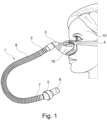
- FIG. 1 The hose 1 according to the invention is shown.
- the hose is connected to a patient 10 via a patient interface 75 and a harness 4.
- the connection between hose 1 and patient interface 75 is made via a mask connector 3, which is curved here and designed with a ball joint.
- the mask connector 3 is pushed over the hose end 2 or inserted into the hose end 2.
- the other hose end is connected to a hose connector 5.
- the Hose connector 5 is designed here with a ball joint and has a nozzle 6 at its end facing away from hose 1, which serves to connect to another ventilation hose, which for example has a larger diameter than hose 1.
- the other hose end 7 can be connected to a nozzle (not shown) which serves to directly connect to a ventilator.
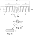
- the ventilation tube 1 according to the invention is shown by way of example with some features.
- the tube has a length 15 which is, for example, 380 to 400 mm, preferably 390 mm.
- the length can also assume other values, for example the tube can have a length of 1000 mm or 2000 mm or even 3000 mm or intermediate values thereof.
- the length 15 is made up of the two tube ends 2, 7 and the tube part 8.
- the tube ends 2, 7 are shown here as being the same length, but they can also have different lengths, thicknesses and shapes.
- the tube ends 2, 7 are preferably 10 - 30 mm long, particularly preferably 20 mm +/-4 mm.
- the tube part 8 usually makes up the majority of the total length 15, in the present case the tube part 8 without the tube ends is approximately 350 mm long.
- the hose is a relatively thin-walled and flexible hose 1 having an external support structure 18 configured as a spiral helix 18 running the length 15 of the hose along its outer wall 17.
- the support structure 18 provides structural strength and rigidity to the hose 1 while also providing flexibility.
- the structural strength and rigidity provided offers protection from crushing by external forces, helps prevent pressure collapse, and reduces compliance, which is the tendency of a hose to expand or contract with pressure changes.
- the support structure 18 is preferably spiral-shaped or arranged spirally around the hose, other shapes are possible.
- Fig. 2c shows a section through the tube along the line AA, partially looking at the interior of the tube.
- the inner surface 23 of the tube may be smooth, which helps to minimize both the inspiratory and expiratory flow resistance.
- the outer surface of the tube is characterized by the helix 18, which is connected to the outer wall 17.
- Fig. 2b shows an enlarged section of the Fig. 2c .
- the helix 18 is connected directly to the outer wall 17 (permanently) with a bottom side.
- the helix 18 extends from the bottom to the top in a rounded manner and thus tapers towards the maximum helix height 20.
- the width 24 of the helix is (on the bottom side, which rests on the outer wall) in the range 1.8 - 4 mm, preferably 2.3 - 3.3 mm and particularly preferably 2.9 mm +/- 0.4 mm.
- the helix height 20 is in the range 1.5 to 3 mm, preferably 2.3 mm, measured perpendicularly from the outer wall 17.
- the distance between two helices 18 corresponds to the pitch 21.
- the pitch is preferably in the range 3 - 8 mm, particularly preferably it is 5 mm +/- 0.5 mm.
- the pitch 21 is determined directly on the outer wall 17, where the helix rests. Because the helix tapers with increasing distance from the outer wall 17, the distance between two helixes 18 is different in at least three places.
- the tapering width 24 of the helix 18 contributes to the hose being more flexible overall, since in the case of strong bending, the outward-facing areas of the helix only touch each other late.
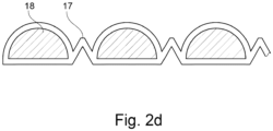
- Fig. 2d also shows an enlarged section of the Fig. 2c
- the helix 18 is connected directly to the outer wall 17 with a lower side. Due to the compression process, the wall between the helices is folded like an accordion. The structural basis for the tube is provided in particular by the helix.
- Fig.3 shows the basic structure of a ventilator 70, which is provided with a display device 71, at least one control element 72 and a hose connection 73.
- a patient interface (for example designed as a breathing mask) 75 is typically connected to the hose connection 73 via a ventilation hose 74.
- the patient interface 75 and the ventilation hose 1 for supplying a patient with respiratory gas are not shown.
- the ventilator 70 has an internal respiratory gas source 76, typically in the form of a blower, and a control 77 for this respiratory gas source 76.
- the ventilator 70 also has a measuring unit 78 and a storage unit 80.
- the display device 71 also serves as an operating unit 84 of a human-machine interface, typically in the form of a touchscreen display.
- the ventilator 70 is typically provided with at least one communication interface 82.
- the interface 82 is arranged in a side area here.
- the interface 82 is inclined to the horizontal and is located in spatial proximity to the display device 71.
- the ventilator 70 also has a further interface 82, which is used to couple modules 85.
- Measuring units in or on the ventilator and/or ventilation tube and/or patient interface are provided for monitoring and controlling flow and pressure, so that the pressure and flow of respiratory gas can be monitored and adjusted if necessary, also taking into account the influences of the ventilation tube and/or patient interface on ventilation.
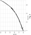
- the graph of FIG. 4 shows the spring rate and elongation of an example hose.
- the determination is preferably carried out where the non-linear change in the graph is shown.
- the graph rises more vertically there (significant increase in load for the same distance). This is the point at which the hose is stretched to its maximum by the helix. If the hose is stretched beyond this yield point, it will no longer return to its original length.
- the strain here is therefore x mm.
- the present invention recognizes that compliance, the amount of expansion of the tubing during a respiratory cycle, is an important design consideration.
- the basic process will now be described.
- the pressure and flow rate through the tubing remain essentially the same during the respiratory cycle.
- a valve on the ventilator is opened during exhalation, allowing the patient to expel breathing gas into the tubing.
- This intermittent increase in pressure exerts expansion forces on the tubing.
- a desired peak pressure must be achieved at the patient's lungs in order to deliver a desired volume of respiratory gas within the inspiration period.
- Lower compliance tubes require a lower flow rate to achieve the desired peak pressure. Since the flow rate remains constant during the inspiratory and expiratory phases, lower compliance tubes have a lower flow rate during the expiratory phase. This lower flow rate desirably results in a lower back pressure against which the patient must exhale. Consequently, the superior low compliance of the present invention reduces the back pressure to just the optimal degree.
- the hose In order to achieve a permanent deformation of the wall, the hose must be heated above the softening temperature of the material.
- the plastic TPE used this is around 70 - 95°C, preferably 85°C.
- production takes place in a sequence of steps
- the heated hose must be compressed so that the properties are changed and maintained.
- the tube is compressed "to the block".
- the helices are adjacent to each other and thus limit the compression.
- the force compressing the hose can be removed.
- the - in the warm introduced - deformations As soon as the temperature of the hose is below the solidification temperature of the material, the - in the warm introduced - deformations.
- this is a temperature of below 85°C, preferably below 80°C or even below 70°C.
Landscapes
- Engineering & Computer Science (AREA)
- Mechanical Engineering (AREA)
- Health & Medical Sciences (AREA)
- Emergency Medicine (AREA)
- Pulmonology (AREA)
- Anesthesiology (AREA)
- Biomedical Technology (AREA)
- Heart & Thoracic Surgery (AREA)
- Hematology (AREA)
- Life Sciences & Earth Sciences (AREA)
- Animal Behavior & Ethology (AREA)
- General Health & Medical Sciences (AREA)
- Public Health (AREA)
- Veterinary Medicine (AREA)
- General Engineering & Computer Science (AREA)
- Rigid Pipes And Flexible Pipes (AREA)
Abstract
Description
- Das Gebiet der vorliegenden Erfindung bezieht sich auf verbesserte Beatmungsschläuche.
- Beatmungsschläuche sind ein wichtiger Bestandteil der medizinischen Beatmung. Die medizinische Beatmung wird bei Patienten mit Schwierigkeiten beim Atmen eingesetzt. Einige wichtige Faktoren, die bei Beatmungsschläuchen zu berücksichtigen sind: Beatmungsschläuche sollten flexibel sein, um sich den Bewegungen des Patienten anzupassen und die Intubation dadurch so angenehm wie möglich zu gestalten, weil bei Bewegungsänderungen oder ruckartige Bewegungen die entstehenden Krafteinwirkungen nicht unmittelbar bzw. unvermindert auf den Körper des Patienten einwirken. Die Größe des Beatmungsschlauchs ist bei einer invasiven, medizinischen Beatmung wichtig, um sicherzustellen, dass er zum Durchmesser der Atemwege des Patienten passt und eine ausreichende Luftzufuhr gewährleistet.
- Beatmungsschläuche sollten aus einem Material hergestellt werden, das für den Patienten sicher ist und keine Allergien auslöst. Üblicherweise werden Schläuche beispielsweise aus TPE, Silikon oder PVC hergestellt. Die meisten Beatmungsschläuche bestehen aus flexiblem PVC-Material. Bei der Auswahl der Materialien müssen die Eigenschaften des Materials berücksichtigt werden, wie zum Beispiel die Flexibilität, die Festigkeit und die chemische Beständigkeit. Die PVC-Materialien werden durch ein Extrusionsverfahren in den gewünschten Schlauchdurchmesser und die Schlauchlänge gebracht. Dabei wird das Material durch eine Düse gepresst und auf eine Welle aufextrudiert, welche für die Innenformgebung und für das Wickeln und Formen des Schlauchs zuständig ist, sowie durch Kühlung zu einem festen Schlauch geformt. Eine gute Dichtigkeit des Beatmungsschlauchs ist entscheidend, um sicherzustellen, dass der Patient ausreichend Sauerstoff erhält und keine Luft entweicht. Beatmungsschläuche sollten über Anschlüsse verfügen, die es ermöglichen, sie sicher an das Beatmungsgerät oder die Atemmaske des Patienten anzuschließen. Die Länge des Schlauchs ist wichtig, um sicherzustellen, dass er lang genug ist, um bequem angeschlossen zu werden, aber nicht so lang, dass er unnötige Verwicklungen oder Verdrehungen verursacht, welche die erforderliche Sauerstoffzufuhr drosseln oder gar unterbrechen könnten. Beatmungsschläuche können steril sein, um Infektionen beim Patienten zu vermeiden. Beatmungsschläuche sind in der Regel jedoch nicht steril, was die Herstellungskosten senkt. Zudem sollten Beatmungsschläuche gut markiert sein, um die Positionierung im Körper des Patienten zu erleichtern und eine sichere Anwendung zu gewährleisten. Schläuche nach dem Stand der Technik sind in bestimmten Grenzen flexibel und nachgiebig.
- Demgegenüber ist es die Aufgabe der vorliegenden Erfindung, einen Schlauch für die medizinische Beatmung zu verbessern. Insbesondere soll dieser komfortabler und zugleich zuverlässiger sein.
- Diese Aufgabe wird mit einem Schlauch des Anspruchs 1 sowie mit einem Verfahren gemäß Anspruch 16 gelöst. Weiterbildungen und vorteilhafte Ausgestaltungen sind Gegenstand der Unteransprüche. Weitere Vorteile und Merkmale ergeben sich aus der allgemeinen Beschreibung und der Beschreibung der Ausführungsbeispiele. Während der Schlauch der vorliegenden Erfindung flexibel ist, ist er wünschenswerterweise auch weniger nachgiebig als Versionen des Standes der Technik. Vergleicht man einen Schlauch des Standes der Technik mit dem Schlauch der vorliegenden Erfindung, zeigt sich, dass der Schlauch des Standes der Technik sowohl axial als auch radial leichter expandiert wird.
- Der erfindungsgemäße Schlauch bietet viele Vorteile. Einen erheblichen Vorteil bietet ein Beatmungsschlauch mit einer durchgehenden Wand, die ein inneres Lumen begrenzt, wobei das Lumen zur Leitung von Atemgas ausgebildet ist, wobei eine Helix die Wand, auf der dem Lumen abgewandten Seite spiralförmig umgibt, wobei die Wand aus einem ersten Material hergestellt ist und wobei die Helix aus einem zweiten Material hergestellt ist, wobei die Helix mit der Wand verbunden ist.
- Die Helix und die Wand können auch aus unterschiedlichen Materialien hergestellt sein.
- In allen Ausgestaltungen ist es besonders vorteilhaft und bevorzugt, dass die Helix eine Unterseite aufweist und mittels dieser unmittelbar und dauerhaft mit der Außenwand verbunden ist.
- Es ist ebenfalls vorteilhaft und bevorzugt, dass die Helix im Querschnitt eine gerundete Außenkontur aufweist und sich von der Unterseite zu einer Oberseite verjüngt, in Richtung einer maximalen Helix-Höhe.
- Die Helix-Höhe ist im Bereich 1,5 bis 3 mm, bevorzugt bei 2,3 mm, gemessen senkrecht von der Außenwand wegweisend.
- In allen Ausgestaltungen ist es auch besonders vorteilhaft und bevorzugt, dass die Breite der Helix (an der Unterseite, die der Außenwand aufliegt) im Bereich 1,8 - 4 mm, bevorzugt 2,3 - 3,3 mm und besonders bevorzugt bei 2,9 mm +/- 0,4 mm liegt.
- In einer vorteilhaften Ausgestaltung entspricht der Abstand zwischen zwei Helices der Steigung der Helix, wobei die Steigung bevorzugt, im Bereich 2 - 8 mm, bevorzugt auch im Bereich 3 - 7 mm, besonders bevorzugt bei 5 mm +/- 0,5 mm liegt.
- Die Steigung wird direkt an der Außenwand, dort wo die Helix aufliegt, bestimmt.
- Es ist ebenfalls vorteilhaft und bevorzugt, dass sich die Helix mit zunehmender Entfernung von der Außenwand verjüngt, wodurch der Abstand zwischen zwei benachbarten Helices zueinander an zumindest drei Stellen unterschiedlich ist und wobei der Abstand zwischen zwei benachbarten Helices im Bereich der maximalen Helix-Höhe am größten ist.
- In allen Ausgestaltungen ist es besonders vorteilhaft und bevorzugt, dass die Leckage des Schlauches bei einem Atemgasdruck von 60 hPa kleiner 15 ml/min/m, bevorzugt kleiner 12 ml/min/m und besonders bevorzugt kleiner 10 ml/min/m ist. Eine Leckage im Beatmungsschlauch kann sehr gefährlich sein, da sie die Wirksamkeit der Beatmung beeinträchtigt und zu einer unzureichenden Atemgasversorgung des Patienten führen kann. Wenn eine Leckage im Beatmungsschlauch vermutet wird, sollte der Schlauch sofort ausgetauscht werden. Vor dem Austausch des Schlauchs sollte der Patient jedoch auf eine alternative Atemgasversorgung, wie z.B. eine manuelle Beatmung, umgestellt werden, um sicherzustellen, dass der Patient weiterhin ausreichend mit Sauerstoff versorgt wird.
- Es ist auch wichtig, regelmäßig die Schläuche und alle anderen Beatmungsgeräte auf mögliche Leckagen oder andere Probleme zu überprüfen, um die Sicherheit des Patienten zu gewährleisten. Eine Schlauchleckage bezieht sich auf eine undichte Stelle oder ein Loch in einem Schlauch, durch die das Atemgas austreten kann. Schlauchleckagen können verschiedene Ursachen haben, wie beispielsweise Abnutzung, Beschädigung durch scharfe Gegenstände, unzureichende Befestigung, Druckänderungen, Alterung des Materials und viele andere. Insbesondere kann jedoch schon ein ungeeignetes Material auch ohne eine Beschädigung eine solche Leckage aufweisen, so dass eine Beatmung mit einem Schlauch aus diesem nicht geeigneten Material die Versorgung des Patienten gefährdet.
- Es ist ebenfalls vorteilhaft und bevorzugt, dass die Federrate im Bereich 25 N/m ist oder größer 25 N/m, bevorzugt größer 27 N/m und besonders bevorzugt größer 30 N/m ist.
- Die Federrate bezieht sich auf die Steifigkeit oder Elastizität des Schlauchmaterials. Je höher die Federrate, desto steifer ist der Schlauch und desto schwieriger ist es, ihn zu biegen oder zu verformen. Eine niedrigere Federrate bedeutet eine höhere Flexibilität und eine einfachere Handhabung des Schlauchs. Die Wahl der richtigen Federrate hängt von den Anforderungen der Anwendung ab und kann von Hersteller zu Hersteller variieren. Ein Schlauch mit einer geringen Federrate ist in der Regel flexibler und lässt sich einfacher biegen als ein Schlauch mit einer höheren Federrate. Dadurch kann er besser an verschiedene Formen und Konturen angepasst werden, was in vielen Anwendungen von Vorteil sein kann.
- Ein weiterer Vorteil einer geringen Federrate ist, dass der Schlauch in der Regel weniger anfällig für Risse und Beschädigungen ist, da er sich bei Druckänderungen und Bewegungen besser anpassen kann und somit weniger Spannungen auftreten.
- Allerdings kann ein Schlauch mit einer zu geringen Federrate auch instabil und leicht verformbar werden, was je nach Anwendung zu Problemen führen kann. Es ist daher wichtig, die richtige Federrate für die jeweilige Anwendung zu wählen.
- Die Federrate eines Beatmungsschlauchs bezieht sich auf die Steifigkeit oder Widerstandsfähigkeit der Helix innerhalb des Schlauchs. Eine höhere Federrate bedeutet, dass mehr Druck erforderlich ist, um den Schlauch auszudehnen, während eine niedrigere Federrate bedeutet, dass weniger Druck erforderlich ist. Die Wahl der richtigen Federrate hängt von verschiedenen Faktoren ab, wie z.B. dem Druck und Volumen des Gases, das durch den Schlauch fließt, sowie den Anforderungen an die Beatmung des Patienten.
- Eine hohe Federrate bei einem Schlauch bedeutet typischerweise, wenn steifere Materialien verwendet werden, dass der Schlauch steifer und widerstandsfähiger gegenüber Verformungen ist.
- Bei der vorliegenden Erfindung ist die Wanddicke der Membrane ähnlich dick, wie bei einem deutlich unflexibleren Schlauch. Die Flexibilität wird über die Geometrie der Helix erzeugt.
- Dies kann verschiedene Vorteile haben, je nach Anwendung des Schlauchs:
Reduzierte Dehnung: Wenn der Schlauch unter Druck steht, dehnt er sich aus. Eine hohe Federrate bedeutet, dass der Schlauch sich weniger dehnt, was den Druckverlust minimiert und die Effizienz der medizinischen Beatmung erhöht. - Präzise Steuerung: Ein steifer Schlauch ermöglicht eine präzisere Steuerung von Atemgasen. Dies ist besonders wichtig für die Vorgabe bestimmter Drücke, Flüsse/Flussgeschwindigkeiten oder Volumina.
- Schläuche mit hoher Federrate halten Belastungen länger stand und sind weniger anfällig für Materialermüdung. Dies kann die Lebensdauer des Schlauchs verlängern.
- Ein steifer Schlauch kann schneller auf Änderungen des Gasstroms reagieren. Dies kann in Anwendungen von Vorteil sein, bei denen Patiententrigger für die Steuerung der Beatmung ausgewertet werden.
- Es ist jedoch zu beachten, dass eine zu hohe Federrate auch zu Nachteilen führen kann, wie z.B. einer erhöhten Wahrscheinlichkeit von Rissen oder Brüchen des Schlauchs bei zu hoher Belastung.
- Compliance und Federrate sind beide Eigenschaften eines Schlauchs, beschreiben jedoch unterschiedliche Aspekte.
- Compliance ist ein Maß für die Fähigkeit des Schlauchs, sich unter einer gegebenen Belastung oder Druckveränderung zu verformen. Es ist das Gegenteil von Steifigkeit und wird in Einheiten von Volumen pro Druckeinheit ausgedrückt. Compliance kann als die Menge an Volumen betrachtet werden, die ein Schlauch pro Einheit angewendeten Drucks ändern kann. Ein Schlauch mit hoher Compliance verformt sich leicht, während ein Schlauch mit geringer Compliance der Verformung widersteht.
- In einer vorteilhaften Ausgestaltung ist die Compliance des Schlauches unter 1,0 ml / hPa / m ist, bevorzugt unter 0,8 und besonders bevorzugt 0,7 oder unter 0,7.
- Die Federrate hingegen ist ein Maß für den Widerstand des Schlauchs gegen Verformung unter einer gegebenen Last oder einem gegebenen Druck. Es ist ein Maß für die Kraft, die erforderlich ist, um den Schlauch um eine bestimmte Länge zu komprimieren oder zu dehnen. Die Federrate wird in Einheiten von Kraft pro Einheit Länge ausgedrückt. Ein Schlauch mit hoher Federrate erfordert mehr Kraft, um ihn zu verformen als ein Schlauch mit niedriger Federrate. Die Federrate berücksichtigt nur eine lineare Zug- oder Druckkraft, um den Schlauch zu stauchen oder zu dehnen. Bei der Compliance liegt der Druck im Inneren des Schlauchs überall an. Hier hat die Geometrie der Wand weniger Einfluss als die Steifigkeit und die Wandstärke.
- Zusammenfassend lässt sich sagen, dass die Compliance angibt, wie viel sich ein Schlauch unter einem gegebenen Druck verformt, während die Federrate misst, wie viel Kraft erforderlich ist, um den Schlauch um eine bestimmte Länge zu verformen. Je größer die Federrate ist, desto kleiner ist die Compliance, weil die größere Starrheit des Schlauches zugleich weniger Verformung unter Druck zulässt.
- Der Schlauch ist vorzugsweise dazu geeignet und ausgebildet, dass die Dehnbarkeit im Bereich 3-39% liegt, bevorzugt im Bereich 5-36% und besonders bevorzugt im Bereich 8-30%.
- Die Dehnbarkeit von Beatmungsschläuchen variiert je nach Material und Hersteller. In der Regel werden Beatmungsschläuche aus flexiblen Materialien wie TPE, Silikon oder PVC hergestellt, um eine gewisse Dehnbarkeit und Flexibilität zu gewährleisten. Die Dehnbarkeit wird oft durch den sogenannten "Dehnungsfaktor" angegeben, der angibt, um wie viel Prozent sich der Schlauch dehnen lässt, bevor er reißt oder beschädigt wird.
- Es ist jedoch wichtig zu beachten, dass die Dehnbarkeit von Beatmungsschläuchen nicht der einzige Faktor ist, der bei der Auswahl eines geeigneten Schlauchs berücksichtigt werden sollte. Auch andere Faktoren wie Größe, Form, Wandstärke, Materialqualität und Verträglichkeit mit Desinfektionsmitteln müssen berücksichtigt werden, um einen geeigneten Schlauch für die medizinische Beatmung zu wählen. Die Dehnbarkeit eines Beatmungsschlauchs hängt von verschiedenen Faktoren ab, wie zum Beispiel dem Material, aus dem der Schlauch hergestellt ist, der Größe des Schlauchs und der Art der Belastung, der er ausgesetzt ist. Generell sind Beatmungsschläuche aus flexiblen Materialien wie z.B. Silikon oder Polyurethan gefertigt, die eine gewisse Dehnbarkeit aufweisen, um eine maximale Luftzufuhr und -abfuhr zu gewährleisten. Die genaue Dehnbarkeit hängt jedoch von der spezifischen Konstruktion und Herstellung des Schlauchs ab.
- In einer vorteilhaften Ausgestaltung ist die Wand aus einem ersten Material TPE oder Silikon oder PVC und die Helix aus einem zweiten Material TPE oder Silikon oder PVC hergestellt.
- Es ist möglich und vorteilhaft, dass das erste Material und das zweite Material identisch sind. Bei TPE kann die Verwendung in unterschiedlichen Härtegraden erfolgen.
- Erfindungsgemäß ist der Schlauch auch so ausgebildet, dass das Gewicht pro Länge bei unter 1000g/m liegt, bevorzugt im Bereich zwischen 500 und 1000 g/m, besonders bevorzugt im Bereich zwischen 550 und 800 g/m.
- Der vorliegende Beatmungsschlauch ist auch für Säuglinge, Neonaten und Frühgeborene anwendbar. Die Atemfrequenz eines Säuglings ist sehr hoch, sodass der Atemzyklus oder die Zeitspanne von der Einatmungsphase bis zur Ausatmungsphase sehr kurz ist. Die Lungen eines Frühgeborenen sind klein und steif und erfordern eine noch höhere Atemfrequenz, d. h. einen kürzeren, schnelleren Zyklus. Folglich ist während der Inspirations- oder Inhalationsphase eine hohe Flussrate erforderlich, um das gewünschte Atemgasvolumen innerhalb dieses kurzen Zyklus zu den Lungen des Säuglings zu übertragen. Je höher der Spitzendruck ist, desto höher ist die Durchflussrate, die erforderlich ist, um diesen Spitzendruck zu erreichen. Mit zunehmender Flussrate steigt auch der Ausatmungswiderstand (expiratorischer Gegendruck). Während der Ausatemphase muss der Patient Atemgas ausatmen. Es ist erwünscht, den Gegendruck innerhalb des Schlauches zu minimieren, damit der Patient diesen Druck beim Ausatmen nicht kraftraubend überwinden muss (expiratorischer Widerstand). Es ist daher wünschenswert, die Quellen sowohl des exspiratorischen Gegendrucks als auch des exspiratorischen Widerstands zu minimieren.
- Durch die einzigartige Kombination des dünnwandigen Schlauchs und der Stützstruktur wird eine hohe Flexibilität der erfindungsgemäßen Schläuche erreicht.
- Diese sind beispielhaft aus POLYVINYLCHLORID (PVC) oder POLYETHYLEN (PE) oder POLYPROPYLEN (PP) oder POLYESTER oder Silikon oder TPE hergestellt.
- Die Erfindung umfasst auch ein Verfahren zur Herstellung eines Beatmungsschlauches mit einer durchgehenden Wand die ein inneres Lumen begrenzt in einem Extrusionsprozess, wobei das Lumen zur Leitung von Atemgas ausgebildet ist, wobei eine Helix die Wand auf der dem Lumen abgewandten Seite spiralförmig umgibt, wobei die Wand aus einem ersten Material hergestellt wird und wobei die Helix aus einem zweiten Material hergestellt wird dadurch gekennzeichnet, dass die Helix mit der Wand verbunden ist. Helix und Wand werden in einem Co-Extrusionsprozess hergestellt.
- Die Helix ist notwendig, um dem Schlauch eine gewisse Stabilität zu verleihen, z.B. gegen äußere Krafteinwirkung. Bevorzugt sind Helix und Wand aus demselben Material.
- Der erste Schritt des Verfahrens ist die Co-Extrusion des Ausgangsschlauches. Danach erfolgen die nachfolgend beschriebenen Verfahrensschritte, um den Schlauch flexibler und dehnbarer zu machen.
- Bei dem Verfahren wird bevorzugt in einem Verfahrensschritt der Schlauch über die Erweichungstemperatur des Materials erwärmt und in einem zweiten Verfahrensschritt der Schlauch bezogen auf seine ursprüngliche Länge gestaucht und in einem dritten Verfahrensschritt der Schlauch abgekühlt, bis die Erstarrungstemperatur des Materials unterschritten ist.
- Bei dem Verfahren erfolgen die Erwärmung und Stauchung unmittelbar nacheinander, bevor der gestauchte Schlauch abgekühlt wird.
- Bei dem Verfahren wird der Schlauch auf über 70°C, bevorzugt auf über 80°C erwärmt und auf einem Block mechanisch gestaucht, sodass die Helices einander berühren. Dann wird der Schlauch auf eine Temperatur von unter 80°C, bevorzugt unter 70°C gekühlt, bevor die Stauchung beendet wird.
- Der Schlauch wird bevorzugt von innen erwärmt und von innen gekühlt, beispielsweise durch einen Gasstrom.
- Im Rahmen dieser Patentanmeldung werden die Begriffe Schlauch und Beatmungsschlauch synonym verwendet.
- Die erfindungsgemäßen Schläuche stellen durch die folgenden Vorteile eine optimale Beatmung sicher: Ein transparenter Schlauch macht eine ständige Überwachung des Schlauchystems möglich. Eine verstärkende äußere Helix hält den Schlauchdurchmesser konstant, selbst wenn dieser gebogen ist. Der Schlauch ist somit flexibel und knickfest, sodass das Risiko einer Beatmungsverringerung oder -unterbrechung reduziert ist. Eine sehr niedrige Compliance stellt eine komfortable Anwendung sicher. Zugleiche weiche, leckagesichere und flexible Anschlüsse stellen eine perfekte Abdichtung sicher. Die Konnektoren sind direkt in den Schlauch integriert, um dichte Verbindungen sicherzustellen und Undichtigkeiten zu vermeiden. Die Schläuche können durch die Dehnbarkeit in der Länge ausgezogen werden.
- In
Figur 1 ist der erfindungsgemäße Schlauch 1 dargestellt. Der Schlauch ist hier über ein Patienteninterface 75 und eine Bänderung 4 an einen Patienten 10 konnektiert. Die Verbindung zwischen Schlauch 1 und Patienteninterface 75 erfolgt über einen Maskenverbinder 3, die hier gekrümmt und mit einem Kugelgelenk ausgeführt ist. Der Maskenverbinder 3 wird über das Schlauchende 2 geschoben oder in das Schlauchende 2 eingeführt. Das andere Schlauchende ist mit einem Schlauchverbinder 5 verbunden. Der Schlauchverbinder 5 ist hier mit einem Kugelgelenk ausgeführt und weist an seinem dem Schlauch 1 abgewandten Ende einen Stutzen 6 auf, der der Verbindung mit einem anderen Beatmungsschlauch dient, der beispielsweise einen größeren Durchmesser als der Schlauch 1 aufweist. Alternativ kann das andere Schlauchende 7 mit einem nicht gezeigten Stutzen verbunden werden, der der direkten Konnektierung an ein Beatmungsgerät dient. - In
Figur 2 ist der erfindungsgemäße Beatmungsschlauch 1 beispielhaft mit einigen Merkmalen dargestellt. Der Schlauch hat eine Länge 15, die beispielsweise bei 380 bis 400 mm liegt, bevorzugt bei 390 mm. Die Länge kann auch andere Werte annehmen, beispielsweise kann der Schlauch eine Länge von 1000 mm oder 2000 mm oder auch 3000 mm oder Zwischenwerten davon aufweisen. Die Länge 15 setzt sich zusammen aus den beiden Schlauchenden 2, 7 und dem Schlauchteil 8. Die Schlauchenden 2, 7 sind hier gleichlang dargestellt, sie können jedoch auch unterschiedliche Längen, Dicken und Formen aufweisen. Die Schlauchenden 2, 7 sind hier bevorzugt 10 - 30 mm lang, besonders bevorzugt 20 mm +/-4mm. Das Schlauchteil 8 macht üblicherweise den überwiegenden Teil der Gesamtlänge 15 aus, vorliegend ist das Schlauchteil 8 ohne die Schlauchenden etwa 350 mm lang. - Wie in den
Fig.1 und2 gezeigt, ist der Schlauch ein relativ dünnwandiger und flexibler Schlauch 1 mit einer äußeren Stützstruktur 18, die als spiralförmige Helix 18 ausgeführt ist, die über die Länge 15 des Schlauchs entlang seiner Außenwand 17 verläuft. Die Stützstruktur 18 verleiht dem Schlauch 1 strukturelle Festigkeit und Steifheit, während sie zudem eine Flexibilität bereitstellt. Die bereitgestellte strukturelle Festigkeit und Steifigkeit bietet Schutz vor Quetschungen durch äußere Kräfte, hilft, einen Druckkollaps zu vermeiden, und verringert die Nachgiebigkeit, die die Tendenz eines Schlauchs ist, sich bei Druckänderungen auszudehnen oder zusammenzuziehen. Obwohl die Stützstruktur 18 vorzugsweise spiralförmig ist oder spiralförmig um den Schlauch herum angeordnet ist, sind andere Formen möglich. -
Fig. 2c zeigt einen Schnitt durch den Schlauch entlang der Linie A-A, teilweise mit Blick auf das Schlauchinnere. Die Innenfläche 23 des Schlauches kann glatt sein, was dazu beiträgt, sowohl den Inspirations- als auch den Exspirations-strömungswiderstand zu minimieren. Die Außenfläche des Schlauches ist geprägt durch die Helix 18, die mit der Außenwand 17 verbunden ist. -
Fig. 2b zeigt einen vergrößerten Ausschnitt derFig. 2c . Die Helix 18 ist mit einer Unterseite unmittelbar mit der Außenwand 17 (dauerhaft) verbunden. Die Helix 18 erstreckt sich von der Unterseite zur Oberseite gerundet und verjüngt sich somit in Richtung der maximalen Helix-Höhe 20. Die Breite 24 der Helix ist (an der Unterseite, die der Außenwand aufliegt) im Bereich 1,8 - 4 mm, bevorzugt 2,3 - 3,3 mm und besonders bevorzugt bei 2,9 mm +/- 0,4 mm. Die Helix-Höhe 20 ist im Bereich 1,5 bis 3 mm, bevorzugt bei 2,3 mm gemessen senkrecht von der Außenwand 17 wegweisend. - Der Abstand zwischen zwei Helices 18 entspricht der Steigung 21. Die Steigung ist bevorzugt im Bereich 3 - 8 mm, besonders bevorzugt liegt sie bei 5 mm +/- 0,5 mm. Die Steigung 21 wird direkt an der Außenwand 17, dort wo die Helix aufliegt, bestimmt. Dadurch, dass sich die Helix mit zunehmender Entfernung von der Außenwand 17 verjüngt, ist der Abstand zwischen zwei Helices 18 zueinander an zumindest drei Stellen unterschiedlich. Die sich verjüngende Breite 24 der Helix 18 trägt dazu bei, dass der Schlauch insgesamt biegsamer ist, da sich bei starker Biegung, die nach außen weisenden Bereiche der Helix erst spät berühren.
-
Fig. 2d zeigt ebenfalls einen vergrößerten Ausschnitt derFig. 2c . Die Helix 18 ist mit einer Unterseite unmittelbar mit der Außenwand 17 verbunden. Bedingt durch den Stauchungsprozess ist die Wand zwischen den Helices Ziehharmonika-artig gefaltet. Die strukturelle Basis für den Schlauch bietet hierbei insbesondere die Helix. -
Fig.3 zeigt den grundsätzlichen Aufbau eines Beatmungsgerätes 70, welches mit einer Anzeigeeinrichtung 71, mindestens einem Bedienelement 72 sowie einem Schlauchanschluss 73 versehen ist. An den Schlauchanschluss 73 wird typischerweise über einen Beatmungsschlauch 74 ein Patienteninterface (beispielsweise als Atemmaske ausgebildet) 75 angeschlossen. Das Patienteninterface 75 und der Beatmungsschlauch 1 zur Atemgasversorgung eines Patienten sind nicht dargestellt. Das Beatmungsgerät 70 weist eine innenliegende Atemgasquelle 76, typischerweise in Form eines Gebläses, sowie eine Steuerung 77 dieser Atemgasquelle 76 auf. Zusätzlich weist das Beatmungsgerät 70 auch eine Messeinheit 78 sowie eine Speichereinheit 80 auf. Die Anzeigeeinrichtung 71 dient neben der Anzeige auch als Bedieneinheit 84 einer Mensch-Maschine-Schnittstelle, typischerweise in Form eines Touchscreen-Displays. Das Beatmungsgerät 70 ist typischerweise mit mindestens einer Kommunikationsschnittstelle 82 versehen. Die Schnittstelle 82 ist hier in einem Seitenbereich angeordnet. Die Schnittstelle 82 ist zur Horizontalen geneigt und befindet sich in räumlicher Nähe zur Anzeigeeinrichtung 71. Bevorzugt weist das Beatmungsgerät 70 zudem eine weitere Schnittstelle 82 auf, die der Kopplung von Modulen 85 dient. Messeinheiten in oder an dem Beatmungsgerät und/oder Beatmungsschlauch und/oder Patienteninterface sind für die Überwachung und Steuerung von Fluss und Druck vorgesehen, so dass der Druck und Fluss von Atemgas überwacht und erforderlichenfalls angepasst werden kann, auch unter Berücksichtigung der Einflüsse von Beatmungsschlauch und/oder Patienteninterface auf die Beatmung. - Der Graph von
FIG. 4 zeigt die Federrate und die Dehnung eines beispielhaften Schlauches. - Die Ermittlung erfolgt bevorzugt dort, wo die nicht lineare Veränderung des Graphen anzeigt wird. Der Graph steigt dort senkrechter an (deutliche Erhöhung der Last bei gleichem Weg). An diesem Punkt liegt die maximale Dehnung des Schlauches durch die Helix. Wenn der Schlauch über diese Streckgrenze gedehnt wird, kommt er nicht mehr in seine Ausgangslänge zurück.
- Die Dehnung beträgt hier also x mm.
- Bei einer Ausgangslänge des Schlauches von y mm
- Ergibt sich beispielsweise eine prozentuale Dehnung von: 15 - 30 %.
- Die Berechnung der Federrate erfolgt mittels folgender Formel:

- Umrechnung δL von mm in m

- Die Ermittlung der Kraft bei dem gewählten Weg von bspw. 20 mm erfolgt anhand des Diagramms. F = 0,75 N
- Berechnung der Helixkonstante:

- Die vorliegende Erfindung berücksichtigt, dass die Nachgiebigkeit, das Ausmaß der Ausdehnung der Schläuche während eines Atmungszyklus, eine wichtige Konstruktionsüberlegung ist. Der Grundprozess wird nun beschrieben. Der Druck und die Flussrate durch den Schlauch bleiben während des Atemzyklus im Wesentlichen gleich. Um den Patienten zu beatmen, wird während des Ausatmens ein Ventil am Beatmungsgerät geöffnet, wodurch der Patient Atemgas in den Schlauch ausstoßen kann. Dieser intermittierende Druckanstieg übt Expansionskräfte auf den Schlauch aus. Während des Einatmungsabschnitts des Atmungszyklus muss ein gewünschter Spitzendruck an den Lungen des Patienten erreicht werden, um ein gewünschtes Atemgasvolumen innerhalb der Einatmungszeitspanne abzugeben.
- Je mehr sich der Schlauch ausdehnt, desto mehr Atemgas muss während der Inhalationsperiode geliefert werden, um den Spitzendruck zu erreichen, damit das gewünschte Atemgasvolumen an die Lunge des Patienten geliefert wird. Daher ist eine geringere Compliance des Schlauches wünschenswert.
- Schläuche mit geringerer Nachgiebigkeit erfordern eine geringere Flussrate, um den gewünschten Spitzendruck zu erreichen. Da die Flussrate während der Inspirations- und Exspirationsphase konstant bleibt, haben Schläuche mit geringerer Compliance während der Exspirationsphase eine geringere Flussrate. Diese niedrigere Strömungsrate führt wünschenswerterweise zu einem niedrigeren Gegendruck, gegen den der Patient ausatmen muss. Folglich reduziert die überlegene niedrige Nachgiebigkeit der vorliegenden Erfindung den Gegendruck in genau dem optimalen Maße.
- Die vorteilhaften Eigenschaften von Schläuchen gemäß der vorliegenden Erfindung lassen sich im Fertigungsprozess durch die Wahl von Material und Fertigungsbedingungen einstellen. Alternativ können erfindungsgemäß auch Schläuche zunächst fertiggestellt und nachträglich so modifiziert werden, dass die vorteilhaften Eigenschaften erzielt werden.
- Vorversuche haben gezeigt, dass das folgende Vorgehen prinzipiell geeignet ist:
- Schlauch (von innen) erwärmen
- Schlauch stauchen
- Schlauch kühlen
- Der Schlauch muss, um eine bleibende Verformung der Wand zu erreichen, über die Erweichungstemperatur des Materials erwärmt werden. Diese ist bei dem verwendeten Kunststoff TPE etwa 70 - 95°C, bevorzugt 85°C.
- Die Herstellung erfolgt beispielsweise in einer Abfolge von Schritten;
- Der erwärmte Schlauch muss gestaucht werden, damit die Eigenschaften geändert werden und erhalten bleiben.
- Der Schlauch wird dazu "auf Block" gestaucht. Dabei grenzen die Helices aneinander und begrenzen so die Stauchung.
- Sobald der Schlauch abgekühlt ist, kann die den Schlauch stauchende Kraft weggenommen werden.
- Sobald die Temperatur des Schlauches unterhalb der Erstarrungstemperatur des Materials ist, bleiben die - im Warmen eingebrachten - Verformungen bestehen. Dies ist bei dem verwendeten Kunststoff eine Temperatur von unter 85°C, bevorzugt unter 80°C oder sogar unter 70°C.
Claims (20)
- Beatmungsschlauch (1) mit einer durchgehenden Wand (17) die ein inneres Lumen (25) begrenzt, wobei das Lumen zur Leitung von Atemgas ausgebildet ist, wobei eine Helix (18) die Wand (17) auf der dem Lumen (25) abgewandten Seite spiralförmig umgibt, wobei die Wand (17) aus einem ersten Material hergestellt ist und wobei die Helix (18) aus einem zweiten Material hergestellt ist dadurch gekennzeichnet, dass die Helix (18) mit der Wand (17) verbunden ist.
- Beatmungsschlauch (1) nach zumindest einem Anspruch 1 dadurch gekennzeichnet, dass die Helix (18) eine Unterseite aufweist und mittels dieser unmittelbar und dauerhaft mit der Außenwand (17) verbunden ist.
- Beatmungsschlauch (1) nach zumindest einem der vorhergehenden Ansprüche dadurch gekennzeichnet, dass die Helix (18) im Querschnitt eine gerundete Außenkontur aufweist und sich von der Unterseite zu einer Oberseite verjüngt in Richtung einer maximalen Helix-Höhe (20).
- Beatmungsschlauch (1) nach zumindest einem der vorhergehenden Ansprüche dadurch gekennzeichnet, dass die Breite (24) der Helix (18) (an der Unterseite, die der Außenwand aufliegt) im Bereich 1,8 - 4 mm, bevorzugt 2,3 - 3,3 mm und besonders bevorzugt bei 2,9 mm +/- 0,4 mm liegt.
- Beatmungsschlauch (1) nach zumindest einem der vorhergehenden Ansprüche dadurch gekennzeichnet, dass der Abstand zwischen zwei Helices (18) der Steigung (21) der Helix entspricht, wobei die Steigung (21) bevorzugt im Bereich 3 - 8 mm, besonders bevorzugt bei 5 mm +/- 0,5 mm liegt.
- Beatmungsschlauch (1) nach zumindest einem der vorhergehenden Ansprüche dadurch gekennzeichnet, dass sich die Helix (18) mit zunehmender Entfernung von der Außenwand (17) verjüngt, wodurch der Abstand zwischen zwei benachbarten Helices (18) zueinander an zumindest drei Stellen unterschiedlich ist und wobei der Abstand zwischen zwei benachbarten Helices (18) im Bereich der maximalen Helix-Höhe (20) am größten ist.
- Beatmungsschlauch (1) nach zumindest einem der vorhergehenden Ansprüche dadurch gekennzeichnet, dass die die Helix (18) die Wand (17) in Form einer Helix umgibt 2,7 mm mit 5 mm Steigung bei einem Innendurchmesser von 015 mm Schlauch.
- Beatmungsschlauch (1) nach zumindest einem der vorhergehenden Ansprüche dadurch gekennzeichnet, dass die die Wand () eine Dicke von 0,05 bis 0,3 mm, bevorzugt 0,1 bis 0,2 mm aufweist.
- Beatmungsschlauch (1) nach zumindest einem der vorhergehenden Ansprüche dadurch gekennzeichnet, dass die Compliance des Schlauches unter 1,2 ml / hPa / m ist, bevorzugt unter 1,0 und besonders bevorzugt unter 0,8 oder auch unter 0,7.
- Beatmungsschlauch (1) nach zumindest einem der vorhergehenden Ansprüche dadurch gekennzeichnet, dass die Leckage bei einem Atemgasdruck von bis zu 60 hPa kleiner 15 ml/min/m, bevorzugt kleiner 12 ml/min/m und besonders bevorzugt kleiner 10 ml/min/m ist.
- Beatmungsschlauch (1) nach zumindest einem der vorhergehenden Ansprüche dadurch gekennzeichnet, dass die Federrate im Bereich 25 N/m ist oder größer 25 N/m, bevorzugt größer 28 N/m und besonders bevorzugt größer 31 N/m ist.
- Beatmungsschlauch (1) nach zumindest einem der vorhergehenden Ansprüche dadurch gekennzeichnet, dass die Dehnbarkeit im Bereich 3-38% liegt, bevorzugt im Bereich 5-34% und besonders bevorzugt im Bereich 8-30%
- Beatmungsschlauch (1) nach zumindest einem der vorhergehenden Ansprüche dadurch gekennzeichnet, dass die Wand aus einem ersten Material Silikon hergestellt ist und wobei die Helix (18) aus einem zweiten Material PVC oder TPE hergestellt ist.
- Beatmungsschlauch (1) nach zumindest einem der vorhergehenden Ansprüche dadurch gekennzeichnet, dass das erste Material und das zweite Material identisch sind.
- Beatmungsschlauch (1) nach zumindest einem der vorhergehenden Ansprüche dadurch gekennzeichnet, dass das Gewicht pro Länge bei unter 1000g/m liegt, bevorzugt im Bereich zwischen 500 und 1000 g/m, besonders bevorzugt im Bereich zwischen 550 und 800 g/m.
- Verfahren zur Herstellung eines Beatmungsschlauches (1) mit einer durchgehenden Wand (17), die ein inneres Lumen (25) begrenzt in einem Extrusionsprozess, wobei das Lumen (25) zur Leitung von Atemgas ausgebildet ist, wobei eine Helix (18) die Wand (17) auf der dem Lumen (25) abgewandten Seite spiralförmig umgibt, wobei die Wand (17) aus einem ersten Material hergestellt wird und wobei die Helix (18) aus einem zweiten Material hergestellt wird dadurch gekennzeichnet, dass die Helix (18) mit der Wand (17) verbunden ist und Helix und Wand in einem Co-Extrusionsprozess hergestellt werden.
- Verfahren zur Herstellung eines Beatmungsschlauches (1) nach Anspruch 16, bei dem in einem ersten Verfahrensschritt der Schlauch über die Erweichungstemperatur des Materials erwärmt wird und in einem zweiten Verfahrensschritt der Schlauch bezogen auf seine ursprüngliche Länge gestaucht wird und in einem dritten Verfahrensschritt der Schlauch abgekühlt wird bis die Erstarrungstemperatur des Materials unterschritten ist.
- Verfahren zur Herstellung eines Beatmungsschlauches (1) nach Anspruch 16 oder 17, bei dem die Erwärmung und Stauchung unmittelbar nacheinander erfolgen und bei dem der gestauchte Schlauch abgekühlt wird.
- Verfahren zur Herstellung eines Beatmungsschlauches (1) nach zumindest einem der vorhergehenden Ansprüche bei dem der Schlauch auf über 70°C, bevorzugt auf über 80°C erwärmt wird und auf Block gestaucht wird, sodass die Helices einander berühren, und bei dem der Schlauch auf eine Temperatur von unter 80°C, bevorzugt unter 70°C gekühlt wird, bevor die Stauchung beendet wird.
- Verfahren zur Herstellung eines Beatmungsschlauches (1) nach zumindest einem der vorhergehenden Ansprüche bei dem der Schlauch von innen erwärmt und von innen gekühlt wird.
Applications Claiming Priority (2)
| Application Number | Priority Date | Filing Date | Title |
|---|---|---|---|
| DE102023001816 | 2023-05-05 | ||
| DE102023002102 | 2023-05-24 |
Publications (1)
| Publication Number | Publication Date |
|---|---|
| EP4458397A1 true EP4458397A1 (de) | 2024-11-06 |
Family
ID=90789428
Family Applications (1)
| Application Number | Title | Priority Date | Filing Date |
|---|---|---|---|
| EP24170740.5A Pending EP4458397A1 (de) | 2023-05-05 | 2024-04-17 | Beatmungsschlauch und verfahren zur herstellung eines beatmungsschlauches |
Country Status (3)
| Country | Link |
|---|---|
| US (1) | US20240366904A1 (de) |
| EP (1) | EP4458397A1 (de) |
| DE (1) | DE102024110733A1 (de) |
Citations (5)
| Publication number | Priority date | Publication date | Assignee | Title |
|---|---|---|---|---|
| US6571794B1 (en) * | 2000-10-19 | 2003-06-03 | Mallinckrodt, Inc. | Multi-lumen hose for respirators |
| DE102009009790B3 (de) * | 2009-02-20 | 2010-06-17 | Schauenburg Hose Technology Gmbh | Beheizbarer Schlauch |
| US20140000626A1 (en) * | 2010-10-18 | 2014-01-02 | Fisher & Paykel Healthcare Limited | Nasal cannula, conduit and securement system |
| US20140130931A1 (en) * | 2009-01-15 | 2014-05-15 | Schauenburg Hose Technology Gmbh | Flexible stretch hose having inwardly extending web portions connecting adjacent pairs of reinforcing coils, with hose properties enhanced by annealing |
| WO2022246520A1 (en) * | 2021-05-28 | 2022-12-01 | ResMed Pty Ltd | Conduit for use in a respiratory apparatus |
-
2024
- 2024-04-17 EP EP24170740.5A patent/EP4458397A1/de active Pending
- 2024-04-17 DE DE102024110733.2A patent/DE102024110733A1/de active Pending
- 2024-05-01 US US18/652,537 patent/US20240366904A1/en active Pending
Patent Citations (5)
| Publication number | Priority date | Publication date | Assignee | Title |
|---|---|---|---|---|
| US6571794B1 (en) * | 2000-10-19 | 2003-06-03 | Mallinckrodt, Inc. | Multi-lumen hose for respirators |
| US20140130931A1 (en) * | 2009-01-15 | 2014-05-15 | Schauenburg Hose Technology Gmbh | Flexible stretch hose having inwardly extending web portions connecting adjacent pairs of reinforcing coils, with hose properties enhanced by annealing |
| DE102009009790B3 (de) * | 2009-02-20 | 2010-06-17 | Schauenburg Hose Technology Gmbh | Beheizbarer Schlauch |
| US20140000626A1 (en) * | 2010-10-18 | 2014-01-02 | Fisher & Paykel Healthcare Limited | Nasal cannula, conduit and securement system |
| WO2022246520A1 (en) * | 2021-05-28 | 2022-12-01 | ResMed Pty Ltd | Conduit for use in a respiratory apparatus |
Non-Patent Citations (1)
| Title |
|---|
| ISO5367: "Anaesthetic and respiratory equipment -Breathing sets and connectors", 1 July 2023 (2023-07-01), pages 1 - 12, XP093378189, Retrieved from the Internet <URL:https://cdn.standards.iteh.ai/samples/81540/690b9cf9f8e7421490476fb32a8ad87e/ISO-5367-2023.pdf> [retrieved on 20260317] * |
Also Published As
| Publication number | Publication date |
|---|---|
| DE102024110733A1 (de) | 2024-11-07 |
| US20240366904A1 (en) | 2024-11-07 |
Similar Documents
| Publication | Publication Date | Title |
|---|---|---|
| DE2828447C2 (de) | Laryngealtubus | |
| DE69518314T2 (de) | System zur erzeugung eines kontinuierlichen positiven atemwegdrucks | |
| DE69229396T2 (de) | Endotrachealtuben mit dichtungselement | |
| DE68906161T3 (de) | Ballon für medizinische Einrichtung und dessen Herstellung. | |
| DE2365725B2 (de) | Druckbegrenzungseinrichtung, insbesondere für Anästhesiegeräte | |
| EP0743075B1 (de) | Beatmungsbeutel | |
| DE321666C (de) | Mit Drahteinlage versehene Kanuele, Sonde, Drainroehre o. dgl. rohrfoermige Vorrichtung zum aerztlichen oder hygienischen Gebrauch aus weichem Kautschuk | |
| DE2142546A1 (de) | Vorrichtung zum Fordern eines Stro mungsmittels innerhalb eines Korperkanals | |
| DE3325797A1 (de) | Ballonkatheter, insbesondere endotrachealkatheter | |
| WO2014090680A1 (de) | Druckausgleichsvorrichtung | |
| EP3226949B1 (de) | Vorrichtung zur dynamisch dichtenden okklusion oder raumfullenden tamponade eines hohlorgans | |
| US20140130931A1 (en) | Flexible stretch hose having inwardly extending web portions connecting adjacent pairs of reinforcing coils, with hose properties enhanced by annealing | |
| DE102012006396A1 (de) | Tracheostomietubus | |
| EP2931345B1 (de) | Druckausgleichsballon und verfahren zu dessen herstellung | |
| DE2353641B2 (de) | Katheter | |
| DE60107704T2 (de) | Befestigungsvorrichtung für schlauchelemente | |
| DE102018123562B4 (de) | Beatmungsvorrichtung | |
| DE102024110733A1 (de) | Beatmungsschlauch und Verfahren zur Herstellung eines Beatmungsschlauches | |
| EP3535004B1 (de) | Trachealkanüle mit einer abdichteinrichtung | |
| DE1954942B2 (de) | Vorrichtung zur künstlichen Beatmung | |
| EP3535003B1 (de) | Biegbare trachealbeatmungsvorrichtung | |
| EP4153283B1 (de) | Beatmungsvorrichtung | |
| DE3700239C2 (de) | ||
| EP4176914B1 (de) | Beatmungsvorrichtung mit leitung zum befüllen eines cuffs im trachealabschnitt | |
| DE102019110828A1 (de) | Ballon für medizinische Anwendungen sowie dessen Herstellung |
Legal Events
| Date | Code | Title | Description |
|---|---|---|---|
| PUAI | Public reference made under article 153(3) epc to a published international application that has entered the european phase |
Free format text: ORIGINAL CODE: 0009012 |
|
| STAA | Information on the status of an ep patent application or granted ep patent |
Free format text: STATUS: THE APPLICATION HAS BEEN PUBLISHED |
|
| AK | Designated contracting states |
Kind code of ref document: A1 Designated state(s): AL AT BE BG CH CY CZ DE DK EE ES FI FR GB GR HR HU IE IS IT LI LT LU LV MC ME MK MT NL NO PL PT RO RS SE SI SK SM TR |
|
| P01 | Opt-out of the competence of the unified patent court (upc) registered |
Free format text: CASE NUMBER: APP_61092/2024 Effective date: 20241114 |
|
| STAA | Information on the status of an ep patent application or granted ep patent |
Free format text: STATUS: REQUEST FOR EXAMINATION WAS MADE |
|
| 17P | Request for examination filed |
Effective date: 20250429 |
|
| STAA | Information on the status of an ep patent application or granted ep patent |
Free format text: STATUS: EXAMINATION IS IN PROGRESS |
|
| 17Q | First examination report despatched |
Effective date: 20250924 |