EP4458497A1 - Verfahren zum bearbeiten von rippen oder rillen von luft- oder gaslagern eines rotierenden wellenteils eines verdichters und montage der komponenten des werkstücks - Google Patents
Verfahren zum bearbeiten von rippen oder rillen von luft- oder gaslagern eines rotierenden wellenteils eines verdichters und montage der komponenten des werkstücks Download PDFInfo
- Publication number
- EP4458497A1 EP4458497A1 EP23171496.5A EP23171496A EP4458497A1 EP 4458497 A1 EP4458497 A1 EP 4458497A1 EP 23171496 A EP23171496 A EP 23171496A EP 4458497 A1 EP4458497 A1 EP 4458497A1
- Authority
- EP
- European Patent Office
- Prior art keywords
- shaft
- machining
- grooves
- ribs
- machined
- Prior art date
- Legal status (The legal status is an assumption and is not a legal conclusion. Google has not performed a legal analysis and makes no representation as to the accuracy of the status listed.)
- Withdrawn
Links
Images


Classifications
-
- F—MECHANICAL ENGINEERING; LIGHTING; HEATING; WEAPONS; BLASTING
- F04—POSITIVE - DISPLACEMENT MACHINES FOR LIQUIDS; PUMPS FOR LIQUIDS OR ELASTIC FLUIDS
- F04D—NON-POSITIVE-DISPLACEMENT PUMPS
- F04D29/00—Details, component parts, or accessories
- F04D29/40—Casings; Connections of working fluid
- F04D29/42—Casings; Connections of working fluid for radial or helico-centrifugal pumps
- F04D29/4206—Casings; Connections of working fluid for radial or helico-centrifugal pumps especially adapted for elastic fluid pumps
- F04D29/4226—Fan casings
-
- B—PERFORMING OPERATIONS; TRANSPORTING
- B23—MACHINE TOOLS; METAL-WORKING NOT OTHERWISE PROVIDED FOR
- B23B—TURNING; BORING
- B23B5/00—Turning-machines or devices specially adapted for particular work; Accessories specially adapted therefor
- B23B5/36—Turning-machines or devices specially adapted for particular work; Accessories specially adapted therefor for turning specially-shaped surfaces by making use of relative movement of the tool and work produced by geometrical mechanisms, i.e. forming-lathes
- B23B5/46—Turning-machines or devices specially adapted for particular work; Accessories specially adapted therefor for turning specially-shaped surfaces by making use of relative movement of the tool and work produced by geometrical mechanisms, i.e. forming-lathes for turning helical or spiral surfaces
- B23B5/48—Turning-machines or devices specially adapted for particular work; Accessories specially adapted therefor for turning specially-shaped surfaces by making use of relative movement of the tool and work produced by geometrical mechanisms, i.e. forming-lathes for turning helical or spiral surfaces for cutting grooves, e.g. oil grooves of helicoidal shape
-
- B—PERFORMING OPERATIONS; TRANSPORTING
- B23—MACHINE TOOLS; METAL-WORKING NOT OTHERWISE PROVIDED FOR
- B23B—TURNING; BORING
- B23B1/00—Methods for turning or working essentially requiring the use of turning-machines; Use of auxiliary equipment in connection with such methods
-
- B—PERFORMING OPERATIONS; TRANSPORTING
- B23—MACHINE TOOLS; METAL-WORKING NOT OTHERWISE PROVIDED FOR
- B23B—TURNING; BORING
- B23B29/00—Holders for non-rotary cutting tools; Boring bars or boring heads; Accessories for tool holders
- B23B29/04—Tool holders for a single cutting tool
- B23B29/12—Special arrangements on tool holders
- B23B29/125—Vibratory toolholders
-
- F—MECHANICAL ENGINEERING; LIGHTING; HEATING; WEAPONS; BLASTING
- F04—POSITIVE - DISPLACEMENT MACHINES FOR LIQUIDS; PUMPS FOR LIQUIDS OR ELASTIC FLUIDS
- F04D—NON-POSITIVE-DISPLACEMENT PUMPS
- F04D17/00—Radial-flow pumps, e.g. centrifugal pumps; Helico-centrifugal pumps
- F04D17/08—Centrifugal pumps
- F04D17/10—Centrifugal pumps for compressing or evacuating
- F04D17/12—Multi-stage pumps
- F04D17/122—Multi-stage pumps the individual rotor discs being, one for each stage, on a common shaft and axially spaced, e.g. conventional centrifugal multi- stage compressors
-
- F—MECHANICAL ENGINEERING; LIGHTING; HEATING; WEAPONS; BLASTING
- F04—POSITIVE - DISPLACEMENT MACHINES FOR LIQUIDS; PUMPS FOR LIQUIDS OR ELASTIC FLUIDS
- F04D—NON-POSITIVE-DISPLACEMENT PUMPS
- F04D25/00—Pumping installations or systems
- F04D25/02—Units comprising pumps and their driving means
- F04D25/06—Units comprising pumps and their driving means the pump being electrically driven
-
- F—MECHANICAL ENGINEERING; LIGHTING; HEATING; WEAPONS; BLASTING
- F04—POSITIVE - DISPLACEMENT MACHINES FOR LIQUIDS; PUMPS FOR LIQUIDS OR ELASTIC FLUIDS
- F04D—NON-POSITIVE-DISPLACEMENT PUMPS
- F04D29/00—Details, component parts, or accessories
- F04D29/02—Selection of particular materials
- F04D29/023—Selection of particular materials especially adapted for elastic fluid pumps
-
- F—MECHANICAL ENGINEERING; LIGHTING; HEATING; WEAPONS; BLASTING
- F04—POSITIVE - DISPLACEMENT MACHINES FOR LIQUIDS; PUMPS FOR LIQUIDS OR ELASTIC FLUIDS
- F04D—NON-POSITIVE-DISPLACEMENT PUMPS
- F04D29/00—Details, component parts, or accessories
- F04D29/05—Shafts or bearings, or assemblies thereof, specially adapted for elastic fluid pumps
- F04D29/051—Axial thrust balancing
-
- F—MECHANICAL ENGINEERING; LIGHTING; HEATING; WEAPONS; BLASTING
- F04—POSITIVE - DISPLACEMENT MACHINES FOR LIQUIDS; PUMPS FOR LIQUIDS OR ELASTIC FLUIDS
- F04D—NON-POSITIVE-DISPLACEMENT PUMPS
- F04D29/00—Details, component parts, or accessories
- F04D29/05—Shafts or bearings, or assemblies thereof, specially adapted for elastic fluid pumps
- F04D29/053—Shafts
-
- F—MECHANICAL ENGINEERING; LIGHTING; HEATING; WEAPONS; BLASTING
- F04—POSITIVE - DISPLACEMENT MACHINES FOR LIQUIDS; PUMPS FOR LIQUIDS OR ELASTIC FLUIDS
- F04D—NON-POSITIVE-DISPLACEMENT PUMPS
- F04D29/00—Details, component parts, or accessories
- F04D29/05—Shafts or bearings, or assemblies thereof, specially adapted for elastic fluid pumps
- F04D29/056—Bearings
- F04D29/057—Bearings hydrostatic; hydrodynamic
-
- F—MECHANICAL ENGINEERING; LIGHTING; HEATING; WEAPONS; BLASTING
- F04—POSITIVE - DISPLACEMENT MACHINES FOR LIQUIDS; PUMPS FOR LIQUIDS OR ELASTIC FLUIDS
- F04D—NON-POSITIVE-DISPLACEMENT PUMPS
- F04D29/00—Details, component parts, or accessories
- F04D29/26—Rotors specially for elastic fluids
- F04D29/28—Rotors specially for elastic fluids for centrifugal or helico-centrifugal pumps for radial-flow or helico-centrifugal pumps
- F04D29/284—Rotors specially for elastic fluids for centrifugal or helico-centrifugal pumps for radial-flow or helico-centrifugal pumps for compressors
-
- F—MECHANICAL ENGINEERING; LIGHTING; HEATING; WEAPONS; BLASTING
- F16—ENGINEERING ELEMENTS AND UNITS; GENERAL MEASURES FOR PRODUCING AND MAINTAINING EFFECTIVE FUNCTIONING OF MACHINES OR INSTALLATIONS; THERMAL INSULATION IN GENERAL
- F16C—SHAFTS; FLEXIBLE SHAFTS; ELEMENTS OR CRANKSHAFT MECHANISMS; ROTARY BODIES OTHER THAN GEARING ELEMENTS; BEARINGS
- F16C17/00—Sliding-contact bearings for exclusively rotary movement
- F16C17/02—Sliding-contact bearings for exclusively rotary movement for radial load only
- F16C17/026—Sliding-contact bearings for exclusively rotary movement for radial load only with helical grooves in the bearing surface to generate hydrodynamic pressure, e.g. herringbone grooves
-
- B—PERFORMING OPERATIONS; TRANSPORTING
- B23—MACHINE TOOLS; METAL-WORKING NOT OTHERWISE PROVIDED FOR
- B23B—TURNING; BORING
- B23B2215/00—Details of workpieces
- B23B2215/12—Bearing races
-
- B—PERFORMING OPERATIONS; TRANSPORTING
- B23—MACHINE TOOLS; METAL-WORKING NOT OTHERWISE PROVIDED FOR
- B23B—TURNING; BORING
- B23B2220/00—Details of turning, boring or drilling processes
- B23B2220/12—Grooving
-
- B—PERFORMING OPERATIONS; TRANSPORTING
- B23—MACHINE TOOLS; METAL-WORKING NOT OTHERWISE PROVIDED FOR
- B23B—TURNING; BORING
- B23B2222/00—Materials of tools or workpieces composed of metals, alloys or metal matrices
- B23B2222/28—Details of hard metal, i.e. cemented carbide
-
- B—PERFORMING OPERATIONS; TRANSPORTING
- B23—MACHINE TOOLS; METAL-WORKING NOT OTHERWISE PROVIDED FOR
- B23B—TURNING; BORING
- B23B2226/00—Materials of tools or workpieces not comprising a metal
- B23B2226/18—Ceramic
-
- B—PERFORMING OPERATIONS; TRANSPORTING
- B23—MACHINE TOOLS; METAL-WORKING NOT OTHERWISE PROVIDED FOR
- B23B—TURNING; BORING
- B23B2226/00—Materials of tools or workpieces not comprising a metal
- B23B2226/31—Diamond
-
- B—PERFORMING OPERATIONS; TRANSPORTING
- B23—MACHINE TOOLS; METAL-WORKING NOT OTHERWISE PROVIDED FOR
- B23B—TURNING; BORING
- B23B2260/00—Details of constructional elements
- B23B2260/072—Grooves
- B23B2260/0725—Spiral
-
- F—MECHANICAL ENGINEERING; LIGHTING; HEATING; WEAPONS; BLASTING
- F05—INDEXING SCHEMES RELATING TO ENGINES OR PUMPS IN VARIOUS SUBCLASSES OF CLASSES F01-F04
- F05D—INDEXING SCHEME FOR ASPECTS RELATING TO NON-POSITIVE-DISPLACEMENT MACHINES OR ENGINES, GAS-TURBINES OR JET-PROPULSION PLANTS
- F05D2230/00—Manufacture
- F05D2230/10—Manufacture by removing material
- F05D2230/14—Micromachining
-
- F—MECHANICAL ENGINEERING; LIGHTING; HEATING; WEAPONS; BLASTING
- F16—ENGINEERING ELEMENTS AND UNITS; GENERAL MEASURES FOR PRODUCING AND MAINTAINING EFFECTIVE FUNCTIONING OF MACHINES OR INSTALLATIONS; THERMAL INSULATION IN GENERAL
- F16C—SHAFTS; FLEXIBLE SHAFTS; ELEMENTS OR CRANKSHAFT MECHANISMS; ROTARY BODIES OTHER THAN GEARING ELEMENTS; BEARINGS
- F16C2380/00—Electrical apparatus
- F16C2380/26—Dynamo-electric machines or combinations therewith, e.g. electro-motors and generators
Definitions
- the invention relates to a method for machining ribs or grooves of air or gas bearings of a part with a rotating shaft of a high-speed centrifugal fluid compressor, and for assembling the components of the part.
- the compressor is two-stage, and comprises a casing with a fluid inlet and a compressed fluid outlet and contains a shaft mounted to rotate about a longitudinal axis.
- a first compression wheel and a second compression wheel are mounted back to back on the shaft, the first compression wheel constituting a first compression stage and the second compression wheel constituting a second compression stage.
- the centrifugal compressor further comprises a motor, preferably a synchronous electric motor, positioned between the first compression wheel and the second compression wheel and arranged to rotate the shaft.
- At least one axial air or gas bearing is mounted at one end of the shaft, and a front radial air or gas bearing is mounted on a first end of the shaft and a rear radial air or gas bearing is mounted on a second end of the shaft.
- the invention also relates to the part obtained by the machining process, and/or assembly of the components of the part.
- Fluid compressors are generally called turbochargers or centrifugal compressors. They consist of a stator and a rotor forming a permanent magnet synchronous motor (brushless motor). They can reach very high speeds, such as 100,000 at 500,000 rpm.
- the engine drives the compression wheels at high speed, where the compression wheels compress the fluid.
- the fluid can be air, gas, refrigerant or any other suitable fluid. Using two compression wheels allows the fluid to be compressed twice as much.
- compressors can be used for example in a mobile HVAC (heating, ventilation, air conditioning and air conditioning) system with a refrigerant gas such as in electric, hybrid or hydrogen vehicles. These compressors can also be used in a stationary system with a refrigerant gas such as a heat pump.
- a mobile HVAC heating, ventilation, air conditioning and air conditioning
- a refrigerant gas such as in electric, hybrid or hydrogen vehicles.
- These compressors can also be used in a stationary system with a refrigerant gas such as a heat pump.
- These compressors generally comprise a first circuit for the circulation of the fluid to be compressed and a second circuit for the circulation of a coolant used to cool the compressor, and more particularly the motor and the air or gas bearings supporting the motor shaft on the one hand and the electronic components on the other hand.
- a coolant used to cool the compressor
- the high-speed rotation of the motor causes very significant heating, so that the compressor elements must be cooled to avoid damage.
- These circuits are generally provided inside the compressor as such, at least as regards the cooling circuit. None is provided to facilitate the flow of air or the cooling gas during operation of the compressor, particularly at high speed, which is a disadvantage.
- the air or gas bearings supporting the rotor shaft are not designed to support the rotor shaft without friction, which generates significant heating when the rotor rotates at high speed, which is another disadvantage.
- the invention aims in particular to overcome the various drawbacks mentioned above by a method for quickly producing grooves or ribs on a rotor shaft of one piece at each radial air or gas bearing, and on an axial air or gas bearing fixed to the shaft or forming part of the shaft.
- Said grooves on the shaft are arranged in such a way as to overcome gravity when the compressor shaft rotates at high speed in each bearing and to allow the rotating rotor shaft to be held without mechanical contact on a stream of air or gas in the radial bearings, therefore practically without friction.
- the present invention relates to a method of machining ribs or grooves of air or gas bearings of a rotating shaft part of a high-speed fluid compressor, which comprises the features of independent claim 1.
- the present invention also relates to a method of machining ribs or grooves on a part with a rotating shaft and of assembling the components of the part according to independent claims 9 and 10.
- the present invention also relates to a part intended to be rotated around a longitudinal axis of a centrifugal compressor and intended to have ribs or grooves machined according to the machining method, and defined in independent claim 11.
- Embodiments of the part are defined in dependent claims 12 to 15.
- An advantage of the method of machining ribs or grooves on a rotating shaft part to be machined of the compressor in a machining machine lies in the fact that all the ribs or grooves are obtained on a portion to be machined of the rotating part, at once by a machining tool performing reciprocating movements from the beginning to the end of the portion to be machined of the rotating shaft part.
- the reciprocating movements of the machining tool are synchronized with the sinusoidal programming carried out in the machining machine, as well as with the desired arrangement of the ribs or grooves to be made on the portion of the part.
- the workpiece or tool holder carrying the machining tool is also moved in a longitudinal machining direction while the machining tool performs the reciprocating movements.
- the reciprocating movements of the tool are compared to a piezoelectric oscillator where the oscillation frequency can be changed to speed up or slow down the reciprocating movements of the tool according to the programming carried out in the machining machine to obtain the said desired ribs or grooves.
- the tool is once in the machining position in contact with the workpiece and another time without contact with the workpiece.
- the workpiece mainly comprises a shaft fixed to a rotor structure of an electric motor driving it in rotation, or at least one axial air or gas bearing mounted at a first end of the shaft or forming part of the shaft between a compression wheel and a radial air or gas bearing.
- Ribs or grooves may be made on one face or preferably on two faces of the disc of the axial air or gas bearing. Alternatively, these can be made on one face of the static axial bearings facing the axial disc.
- An advantage of the process of machining ribs or grooves in a machining machine is that the ribs or grooves are produced very quickly in less than 1 minute on each portion to be machined of the shaft for radial air or gas bearings and with great precision. The same applies to the grooves or ribs produced on one or two faces of the disk of the axial air or gas bearing driven in rotation.
- the machining tool is of greater hardness than the material of the shaft or the axial air or gas bearing.
- the machining machine can be programmed to have simultaneous turning synchronization with the machining tool according to a sinusoidal programming to obtain an arrangement of the ribs or grooves on each portion to be machined of the shaft for each radial air or gas bearing, and for the axial air or gas bearing.
- the grooves or ribs are machined by the machining machine and the machining tool according to a sinusoidal programming and the arrangement desired grooves or ribs in such a way as to have a reversal of orientation of the grooves or ribs on the shaft substantially towards the inner half of each static radial bearing placed above said ribs. This makes it possible to generate an air or gas pressure which can be increasingly important the faster the shaft rotates.
- Such a high-speed centrifugal fluid compressor can rotate at very high speeds without excessive heating due to the construction of ribs or grooves in the air or gas radial bearings.
- An axial bearing is also provided between the first compression wheel and the first radial bearing.
- Grooves or ribs are made on the periphery in the form of spirals on a front face and a rear face of the axial bearing disc. Air films are generated by the grooves when the shaft rotates to maintain the axis in a longitudinally well-centered position.
- centrifugal compressor all the components forming part of the centrifugal compressor, which are well known in the state of the art, are described only briefly, because the invention essentially relates to the manner of producing ribs or grooves on two portions of a shaft to be covered respectively by two static radial air or gas bearings, or on an axial air or gas bearing.
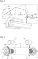
- the centrifugal converter comprises in a housing 2, a shaft 7 made of tungsten carbide or ceramic, rotatably mounted about a longitudinal axis AA passing through the front 2b and rear 2c faces, a first centrifugal compression wheel 8 and a second centrifugal compression wheel 10 mounted back to back at each end of the shaft 7, said first compression wheel 8 constituting a first compression stage and said second compression wheel 10 constituting a second compression stage.
- the shaft 7 is hollow in this embodiment and contains a threaded rod 11, at each end of which is screwed one of the compression wheels 8, 10, which allows easy assembly and disassembly of the compression wheels.
- the rear of the 8 compression wheels and 10 has a labyrinth seal to control pressures in the compressor and balance axial forces.
- the casing 2 also contains a preferably synchronous electric motor positioned between the first compression wheel 8 and the second compression wheel 10 and arranged to rotate the shaft 7.
- the motor comprises a stator 14 and a rotor structure 16 which interact to form a synchronous electric motor with at least one permanent magnet 16a (brushless motor). More particularly, the stator 14 is formed by a coil 14a and two ferrite elements 14b, fixedly mounted relative to the casing 2.
- the rotor structure 16 comprises one or more permanent magnets 16a secured to the shaft 7, for example by gluing, and is covered with a liner 16b. Flanges 16c are fixed (for example by gluing) to the lateral ends of the liner and make it possible to ensure the resistance of the magnet to centrifugal forces at high speeds.
- the part intended to be rotated about a longitudinal axis AA of a centrifugal compressor comprises at least one shaft 7, on or in which is mounted or fixed a rotor structure 16 with at least one permanent magnet 16a of an electric motor to drive the shaft in rotation about the longitudinal axis AA, and an axial air or gas bearing 24 fixed to one end of the shaft 7 or forming part of the shaft 7.
- the part may also comprise a first compression wheel 8 and a second compression wheel 10 mounted at two ends of the shaft 7, a front radial air or gas bearing 18 mounted on a first end of the shaft 7, and a rear radial air or gas bearing 22 mounted on a second end of the shaft 7, as shown in FIG. Figure 2a .
- the machining process is carried out in a machining machine 100 adapted to receive the part to be machined and in particular the shaft 7 with the axial bearing 24 and comprises a tool holder 110 with a tool for machining the ribs or grooves on at least a portion of the shaft 7 of the part.
- the shaft 7 is rotatably mounted in the casing 2 about its longitudinal axis A-A by means of at least one front radial bearing 18, one rear radial bearing 22 and one axial bearing 24.
- the centrifugal compressor 1 comprises a front radial bearing support 26 for supporting the front radial bearing 18, a rear radial bearing support 28 for supporting the rear radial bearing 22, arranged to be positioned around the shaft 7, respectively at the front and at the rear of the engine.
- a volute 29 is also provided between the rear radial bearing support 28 and the rear cover 3c.
- the volute 29 comprises the orifice leading to the tangential fluid outlet 6, after compression.
- An axial bearing support 30 is also provided to support the axial bearing 24 arranged to be positioned around the shaft 7, between the first compression wheel 8 and the front radial bearing support 26. It is obvious that the axial bearing could be provided at the rear of the engine.
- the bearings are non-contact, aerodynamic type, in order to generate little friction. They do not require lubrication and require very little maintenance. More specifically, with reference to the Figures 2a, 2b And 4 , the axial bearing 24 is an aerodynamic bearing and is constituted by a disk comprising on at least one of its faces first grooves 24a, preferably spiral on an annular zone at the periphery, arranged to create an air film.
- the axial bearing 24 comprises grooves or ribs 24a preferably spiral on the periphery of the axial bearing disk 24 on a front face and on a rear face obtained by a machining method explained below. The orientation of the grooves or ribs 24a may be different on the front face relative to the rear face or possibly identical.
- the axial bearing 24 with its grooves or ribs 24a makes it possible to keep the shaft 7 rotating in a longitudinally centered manner by generating air films on the front face and the rear face.
- the front 18 and rear 22 radial bearings are aerodynamic bearings, and the shaft 7 has, opposite the front 18 and rear 22 radial bearings, second grooves or ribs 32 arranged to create a air or gas film when the shaft is rotated in radial air or gas bearings.
- first centrifugal compression wheel 8 and the second centrifugal compression wheel 10 mounted back to back at each end of the shaft 7.
- the rotor structure 16 with at least one permanent magnet 16a is fixed on the shaft in a central position for the electric motor.
- a rotor structure 16 which comprises one or more diametrically magnetized permanent magnets 16a glued, shrunk inside the shaft 7 or arranged in a sleeve 16b.
- the permanent magnet(s) 16a can be shrunk in the sleeve 16b with the greatest possible rigidity and interference to put each magnet in compression in order to compensate for the orthoradial traction due to the centrifugal forces.
- the clearance between the shaft 7 and the magnet 16a or magnets 16a mounted outside the shaft 7 must be sufficient so that there is no clamping of the magnet 16a on the shaft 7 at high speed and high temperature, which would put the interior of the magnet 16a in a state of high biaxial tension and thus increase its risk of breakage.
- the radial displacement of the inner surface of each magnet 16a may be less than the radial displacement of the outer surface of the shaft 7 due to the negative thermal expansion coefficient of the magnet in a radial direction. This is illustrated by the hatched area of the figure 3 where the inner surface of the magnet 16a approaches the outer surface of the shaft 7 at the end of rapid deceleration of the rotor structure 16 when the latter is still hot.
- FIG 3 represents a graph of the difference between a radial displacement of the outer surface of the shaft 7 and that of the surface inner diameter of the permanent magnet 16a or permanent magnets 16a according to the invention, x corresponds to the diametrical magnetization direction of the magnet and y corresponds to the orthogonal direction in which the magnet contracts radially during heating. In the case of assembly by gluing, this difference corresponds to the radial deformation to be elastically accommodated by the glue between the shaft 7 and the permanent magnet 16a.
- a bond can be made between the shaft 7 and the magnet 16a, if the glue supports the radial deformation (up to 10 ⁇ m seen at Figure 3 ) in high temperature and high speed traction. If necessary, if the glue creeps at operating temperature (for example 150°C) or if its elastic modulus decreases by several orders of magnitude, it no longer fulfills its load-recovery role and therefore becomes useless.
- flanges 16c are fixed to the lateral ends of the liner 16b in order to guarantee the mechanical integrity of the magnet 16a or of several magnets 16a parallel side by side on the shaft 7 subjected to centrifugal forces.
- the flanges 16c can be glued or shrink-fitted between the shaft 7 and the liner 16b.
- a glueless assembly is obtained by optimizing the hooping (choice of materials and interferences) of the flanges 16c on the shaft 7, of the flanges 16c in the sleeve 16b and of the sleeve 16b on the magnet 16a. The torque is thus transmitted from the magnet 16a or from each magnet 16a to the shaft 7 via the flanges 16c.
- a glueless assembly guarantees better rigidity than a glued assembly, particularly at high speed and temperature where a glued assembly would see the frequency of its first bending mode decrease dangerously towards the rotation frequency.
- the 16b liner or envelope can ideally be made of carbon fibers and alternatively of titanium or molybdenum alloy.
- the 16c flanges are ideally made of titanium alloy and alternatively of non-magnetic steel.
- the diametrical interference of the 16c flanges in the 16b jacket is ideally the same or slightly less than that of 16b jacket on 16a magnet or magnets.
- the liner 16b and the flanges 16c are made of the same material, it is possible to combine the liner 16b and at least one of the two flanges 16c into a single part, in particular for mounting the permanent magnet structure 16a on an outer side of the shaft 7. It is also possible to replace a flange 16c with a shoulder made on the shaft 7 (shrinking surface for the flange, as well as the axial positioning of the magnet).
- grooves or ribs obtained by laser ablation of the shaft can be produced before or after the assembly of the assembly consisting of the liner 16b, the permanent magnet 16a and the flanges 16c on the shaft 7, it is however preferable to produce these grooves or ribs after the shrink-fitting of the axial disk 24 on the shaft 7 if the magnet 16a is inside the shaft 7. In all cases, it is essential to obtain the final geometry of the bearings (and possibly of the assembly with the axial disk if assembled before finishing) before the laser ablation.
- the magnet 16a can be magnetized before its assembly on the shaft 7, it is preferable to magnetize it after assembly, measurement and balancing of the rotor structure 16 in order to facilitate these steps.
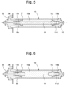
- a first variant is represented in figure 5 with a longitudinal sectional view along the axis AA of the shaft 7 with the compression wheels 8 and 10, at least the axial bearing 24 in one piece with the shaft 7 and the rotor structure 16 with one or more permanent magnets 16a according to the invention arranged inside the shaft 7, which is in tubular form.
- the permanent magnet(s) 16a are shrunk inside the shaft 7 or mounted with a small radial clearance.
- the clearance between the rod 11 and the magnet 16a or the magnets 16a mounted inside the shaft 7 must be sufficient so that there is no tightening of the magnet 16a on the rod 11 at high speed and at high temperature, which would put the interior of the magnet 16a in a state of high biaxial traction and thus increase its risk of breakage.
- the rod is threaded on its two ends 11b and 11d so that it can be screwed on the one hand into an internal thread 8b of the first compression wheel 8, and on the other hand into an internal thread 10b of the second compression wheel 10.
- the shoulder 11c is provided in the case of radial play between the shaft 7 and the magnet 16a in order to axially secure the magnet 16a and the threaded rod 11 after having screwed the compression wheel 8. Tightening the compression wheel 10 makes it possible to axially secure the threaded rod 11 and the shaft 7.
- the magnet 16a When the magnet 16a is inside the shaft 7 and the material of the shaft 7 is too fragile to allow hooping, the magnet 16a is secured to the shaft 7 either by gluing or by axial tightening via a rod prestressed in tension. It is also possible to obtain axial tightening on a solid magnet by machining threads in the shaft directly to screw the wheels that will hold the magnet in the hollow shaft 7.
- the hollow magnet is thus placed in slight axial compression between the shoulder of the rod 11b and the tubular end 8b of the wheel 8.
- the tightening of the wheel 8 makes it possible to compensate for the difference in thermal expansion of the rod 11 and the magnet 16a.
- the tightening of the wheel 10 makes it possible to compensate for the difference in thermal expansion of the rod 11 and the shaft 7 and to maintain sufficient adhesion to transmit the torque.
- FIG 6 represents a second variant of a longitudinal sectional view along the axis AA of the shaft 7 with the compression wheels 8 and 10, at least the axial bearing 24 monobloc with the shaft 7 and the rotor structure 16 with one or more permanent magnets 16a arranged inside the hollow shaft 7.
- This variant combines bonding and axial clamping for the assembly of the almost solid magnet 16a inside the shaft 7.
- rods 11b and 11d threaded at one end only and shouldered at the other end are bonded on their smooth part in the almost solid magnet 16a and screwed on the other side in the wheels.
- the magnet undergoes an axial traction to ensure a pre-load of the wheels on the shaft 7 to allow the transmission of the torque by adhesion.
- FIG 7 represents an embodiment of the axial air or gas bearing 24.
- ribs or grooves 24a of a certain determined depth are produced on an annular zone starting from the periphery of the disk and towards the center of the disk.
- the ribs or grooves 24a and their arrangement are programmed in particular in the machining machine to activate the machining tool in order to produce all the ribs or grooves at once, that is to say by moving the tool holder, or the disk set in rotation in a single machining direction for example from the periphery of the disk to the bottom of the annular zone of the ribs or grooves.
- Starting for example from the periphery of the disk on one of the faces and progressively portions of grooves are formed by back and forth movements of the machining tool in synchronism with the machining machine rotating the disk at a speed determined according to a sinusoidal programming.
- each start of all the grooves 24a is made by the rotation of the disk and the reciprocating movements of the machining tool. This is repeated continuously for the following groove or rib portions continuously from the first portion of the grooves and this until the end or bottom of the annular zone.
- the time The grooved face machining of the disc is carried out in less than a minute, which is significantly different from previous machining carried out by laser beam.
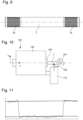
- FIG 8 represents a first portion of ribs or grooves 32 made on a first end of the shaft 7 with a first radial air or gas bearing 18 shown in longitudinal section on the first portion of ribs or grooves 32 made by the machining process.
- the shaft 7 is rotated by the machining machine about its longitudinal axis and moved along its longitudinal axis in a machining direction.
- the machining tool arranged in its tool holder is moved opposite the first portion of the shaft to be machined by making back-and-forth movements at a frequency depending on the programming carried out in the machining machine. It should be noted that instead of moving the shaft 7 in a longitudinal direction, it is also quite conceivable to move the tool holder in the longitudinal machining direction. All the ribs or grooves 32 are obtained on the first portion to be machined of the first end of the shaft driven in rotation, at once by the machining tool making back-and-forth movements from the beginning to the end of the first portion to be machined of the shaft 7.
- the machining machine is programmed to have a simultaneous synchronization of turning of the shaft 7 with the machining tool according to a sinusoidal programming to obtain a determined arrangement of the ribs or grooves 32 on the first portion to be machined of the shaft 7 for the front radial air or gas bearing 18.
- a sinusoidal programming to obtain a determined arrangement of the ribs or grooves 32 on the first portion to be machined of the shaft 7 for the front radial air or gas bearing 18.
- the determined arrangement of the ribs or grooves 32 made on the first portion of the first end of the shaft 7 is programmed in the machining machine.
- the ribs or grooves 32 each have a V shape, i.e. with a change of orientation in principle from the middle of the first portion of the shaft 7 to be machined. This makes it possible to keep the shaft rotated at high speed in the compressor in the air or gas radial bearings without mechanical contact.
- the air or gas pressure in each aerodynamic radial bearing is such that the shaft is no longer in mechanical contact with the static radial bearing, thereby avoiding any mechanical friction.
- FIG 9 represents the shaft 7 with a first ribbed or grooved portion 32 machined on the first end of the shaft and a second portion on the second end of the shaft 7.
- the first portion and the second portion are machined in the same manner as described above in relation to the figure 6 .
- the same arrangement of V-shaped ribs or grooves 32 at both ends of the shaft 7 may be provided.
- the compressor 1 comprises a casing 2, made of aluminum, the upper face 2a of which is closed by an upper cover 3a and the front 2b and rear 2c faces are closed respectively by a front cover 3b and by a rear cover 3c.
- the side faces 2d of the casing are joined at their base to form a bottom 2e having, in cross section, a U shape.
- the upper cover 3a is positioned on the side of the electronic components of the compressor. Thus, access to the electronic components integrated in the compressor is easy, access being via the upper cover 3a.
- the front and rear covers 3b, 3c are used to reach the inside of the compressor (motor, rotor, bearings, etc.).
- a seal is interposed between the upper face of the casing 2 and the upper cover 3a. This seal helps protect electronic components from dust and moisture.
- the casing 2 has an inlet for the fluid to be compressed 5 provided on the front cover 3b and a tangential outlet for the compressed fluid 6 provided on one of the side faces of the casing 2.
- the casing 2 comprises a through inner housing extending coaxially to the longitudinal axis AA between the front face 2b and the rear face 2c of the casing 2 and receiving the front radial bearing support 26 and the front radial bearing 18, the motor and its rotor structure 16 fixed on the shaft 7, the rear radial bearing support 28 and the rear radial bearing 22, the second compression wheel 10 and the volute 29.
- the inner housing On the front face 2b side, the inner housing is closed by the front cover 3b which integrates the first compression wheel 8, the axial bearing support 30 and the axial bearing 24.
- the inner housing is closed by the rear cover 3c.
- At least one orifice for example the point referenced 57a, arranged to allow the fluid to be compressed circulating in the channels to enter the motor and circulate between the stator 14 and the rotor structure 16 and at least one orifice, for example the points referenced 57b, arranged to allow the fluid to be compressed to exit the motor and join said channels after having cooled the motor.
- At least one orifice is advantageously provided, for example the points referenced 59a on the figure 1 arranged to allow the fluid to be compressed circulating in the channels 54 to circulate near the axial 24, front radial 18 and rear radial 22 bearings, and at least one orifice corresponding for example to the same points referenced 57b arranged to allow the fluid to be compressed to join said channels 54 after having cooled said axial 24, front radial 18 and rear radial 22 bearings.
- the fluid to be compressed passes into channels 54 through the parts of the compressor located along the longitudinal axis between the first compression stage and the second compression stage to reach the second compression stage.
- the fluid to be compressed when it passes between the inner wall 52 and the ferrite elements 14b of the motor, cools the latter and recovers the calories lost from the motor in order to increase its efficiency before entering the second compression stage.
- the orifices 57a, 57b, 59a make it possible to achieve a slight deviation of the flow so that the fluid to be compressed also circulates between the stator 14 and the rotor structure 16 and in the bearings to cool these elements and recover the heat losses at the level of the motor and the heat losses due to friction in the bearings.
- the centrifugal compressor 1 makes it possible to achieve very high rotation speeds, between 100,000 rpm and 500,000 rpm. It allows the fluid compressed in the first compression stage to pass substantially throughout the system to recover all the lost heat, and in particular the heat lost at the engine, bearings and electronic components, in order to increase its efficiency before entering the second compression stage (as the temperature of the fluid to be compressed increases, its pressure also increases).
- the use of only the fluid to be compressed to cool the compressor, without the aid of an additional cooling circuit, as well as the arrangement of the electronic components in the compressor to have electronics integrated into the casing make it possible to obtain a very compact compressor.
- the compressor according to the invention therefore has a high rotation speed and a high compression ratio while occupying a restricted volume.
- a compressor according to the invention has a compression ratio greater than 3, and a power of the order of 4 kW for dimensions L ⁇ W ⁇ H in cm of the order of 14 x 8 x 11 for a weight of only 1.6 kg.
- the compressor according to the invention can be used with air or gas to supply fuel cells, or any other system that uses compressed air (industrial compressors, medical compressors, boat compressors, etc.).
- the compressor according to the invention can be used in a mobile HVAC (heating, ventilation, air conditioning and air conditioning) system, such as in electric, hybrid or hydrogen vehicles.
- a mobile HVAC heating, ventilation, air conditioning and air conditioning
- the centrifugal compressor can also be used in a stationary system with a refrigerant gas, such as a heat pump.
- the centrifugal compressor can also be used with natural gas.
- FIG. 10 represents an assembly of the machining machine 100 for producing ribs or grooves on portions of the first end and the second end of the shaft 7.
- the machining machine 100 comprises a machining lathe 130 with a spindle 140 for holding the shaft 7 and rotating it during the machining of the ribs or grooves.
- the spindle which holds the shaft in rotation can move in a longitudinal machining direction for the production of the ribs or grooves as shown by the arrow Sm.
- the machining machine 100 further comprises a tool holder 110 connected to the structure of the machining lathe 130.
- the tool holder 110 carries a machining tool 120 whose machining head which comes into contact with the shaft to machine the grooves or ribs can perform back and forth movements according to a programming of the machining machine.
- the machining tool head 120 can be made of diamond to machine the ribs or grooves on the shaft 7 made of tungsten carbide or ceramic. This is done to have a simultaneous synchronization of turning of the shaft 7 with the machining tool according to a sinusoidal programming to obtain a determined arrangement. ribs or grooves on the portions to be machined of the shaft 7 for each front or rear radial air or gas bearing.
- the tool holder 110 can also in an alternative embodiment be moved in a longitudinal machining direction in place of the shaft 7 for machining the ribs or grooves on the shaft.
- FIG 11 represents a precision rib or groove for air or gas bearings obtained by the back and forth movements of the machining tool well determined according to the material to be machined, the rotation speed of the shaft for machining, the diameter of the shaft and many other parameters.
- FIG 12 represents a machining machine 100 for producing ribs or grooves on one or two faces of the axial air or gas bearing disc 24.
- This machining machine 100 comprises the same elements as those described with reference to the figure 10 and will not be repeated with reference to this figure 12 .
Landscapes
- Engineering & Computer Science (AREA)
- Mechanical Engineering (AREA)
- General Engineering & Computer Science (AREA)
- Physics & Mathematics (AREA)
- Fluid Mechanics (AREA)
- Structures Of Non-Positive Displacement Pumps (AREA)
- Turning (AREA)
- Sliding-Contact Bearings (AREA)
Priority Applications (7)
| Application Number | Priority Date | Filing Date | Title |
|---|---|---|---|
| EP23171496.5A EP4458497A1 (de) | 2023-05-04 | 2023-05-04 | Verfahren zum bearbeiten von rippen oder rillen von luft- oder gaslagern eines rotierenden wellenteils eines verdichters und montage der komponenten des werkstücks |
| EP24169627.7A EP4458498A1 (de) | 2023-05-04 | 2024-04-11 | Verfahren zum schneiden von rippen oder nuten an einem werkstücks und werkstück |
| US18/643,465 US20240369068A1 (en) | 2023-05-04 | 2024-04-23 | Method for machining ribs or grooves for air or gas bearings of a rotary-shaft-comprising workpiece of a compressor, and method for assembling the components of the workpiece |
| JP2024072654A JP7850761B2 (ja) | 2023-05-04 | 2024-04-26 | コンプレッサーの回転シャフトを備えるワークピースの空気ないしガスベアリングのためのリブないし溝を加工して形成する方法、及びワークピースのコンポーネントを組み付ける方法 |
| CN202410539998.6A CN118893250A (zh) | 2023-05-04 | 2024-04-30 | 加工压缩机的包括旋转轴的工件的空气或气体轴承的肋或槽的方法及组装工件的部件的方法 |
| KR1020240057965A KR20240161591A (ko) | 2023-05-04 | 2024-04-30 | 압축기의 회전-샤프트-포함 공작물의 공기 또는 가스 베어링을 위한 리브 또는 홈의 가공 방법, 및 공작물의 구성요소들의 조립 방법 |
| CN202420942083.5U CN222696171U (zh) | 2023-05-04 | 2024-04-30 | 工件 |
Applications Claiming Priority (1)
| Application Number | Priority Date | Filing Date | Title |
|---|---|---|---|
| EP23171496.5A EP4458497A1 (de) | 2023-05-04 | 2023-05-04 | Verfahren zum bearbeiten von rippen oder rillen von luft- oder gaslagern eines rotierenden wellenteils eines verdichters und montage der komponenten des werkstücks |
Publications (1)
| Publication Number | Publication Date |
|---|---|
| EP4458497A1 true EP4458497A1 (de) | 2024-11-06 |
Family
ID=86329307
Family Applications (2)
| Application Number | Title | Priority Date | Filing Date |
|---|---|---|---|
| EP23171496.5A Withdrawn EP4458497A1 (de) | 2023-05-04 | 2023-05-04 | Verfahren zum bearbeiten von rippen oder rillen von luft- oder gaslagern eines rotierenden wellenteils eines verdichters und montage der komponenten des werkstücks |
| EP24169627.7A Pending EP4458498A1 (de) | 2023-05-04 | 2024-04-11 | Verfahren zum schneiden von rippen oder nuten an einem werkstücks und werkstück |
Family Applications After (1)
| Application Number | Title | Priority Date | Filing Date |
|---|---|---|---|
| EP24169627.7A Pending EP4458498A1 (de) | 2023-05-04 | 2024-04-11 | Verfahren zum schneiden von rippen oder nuten an einem werkstücks und werkstück |
Country Status (5)
| Country | Link |
|---|---|
| US (1) | US20240369068A1 (de) |
| EP (2) | EP4458497A1 (de) |
| JP (1) | JP7850761B2 (de) |
| KR (1) | KR20240161591A (de) |
| CN (2) | CN118893250A (de) |
Citations (4)
| Publication number | Priority date | Publication date | Assignee | Title |
|---|---|---|---|---|
| JP2002036004A (ja) * | 2000-07-25 | 2002-02-05 | National Institute Of Advanced Industrial & Technology | 流体軸受の製造方法及び製造装置 |
| US20130235489A1 (en) * | 2012-03-08 | 2013-09-12 | Alphana Technology Co., Ltd. | Rotating device, manufacturing method thereof and bearing component |
| EP3557078A1 (de) * | 2018-04-20 | 2019-10-23 | Belenos Clean Power Holding AG | Fluidverdichter |
| EP4180154A1 (de) * | 2021-11-16 | 2023-05-17 | Belenos Clean Power Holding AG | Verfahren zur bearbeitung von rippen oder nuten von luft- oder gaslagern eines kompressors |
Family Cites Families (2)
| Publication number | Priority date | Publication date | Assignee | Title |
|---|---|---|---|---|
| JPH10328902A (ja) * | 1997-05-26 | 1998-12-15 | Sony Corp | 螺旋溝形成装置 |
| JPH1119804A (ja) * | 1997-07-01 | 1999-01-26 | Sony Corp | 螺旋溝加工装置及び加工方法 |
-
2023
- 2023-05-04 EP EP23171496.5A patent/EP4458497A1/de not_active Withdrawn
-
2024
- 2024-04-11 EP EP24169627.7A patent/EP4458498A1/de active Pending
- 2024-04-23 US US18/643,465 patent/US20240369068A1/en active Pending
- 2024-04-26 JP JP2024072654A patent/JP7850761B2/ja active Active
- 2024-04-30 KR KR1020240057965A patent/KR20240161591A/ko active Pending
- 2024-04-30 CN CN202410539998.6A patent/CN118893250A/zh active Pending
- 2024-04-30 CN CN202420942083.5U patent/CN222696171U/zh active Active
Patent Citations (4)
| Publication number | Priority date | Publication date | Assignee | Title |
|---|---|---|---|---|
| JP2002036004A (ja) * | 2000-07-25 | 2002-02-05 | National Institute Of Advanced Industrial & Technology | 流体軸受の製造方法及び製造装置 |
| US20130235489A1 (en) * | 2012-03-08 | 2013-09-12 | Alphana Technology Co., Ltd. | Rotating device, manufacturing method thereof and bearing component |
| EP3557078A1 (de) * | 2018-04-20 | 2019-10-23 | Belenos Clean Power Holding AG | Fluidverdichter |
| EP4180154A1 (de) * | 2021-11-16 | 2023-05-17 | Belenos Clean Power Holding AG | Verfahren zur bearbeitung von rippen oder nuten von luft- oder gaslagern eines kompressors |
Also Published As
| Publication number | Publication date |
|---|---|
| US20240369068A1 (en) | 2024-11-07 |
| KR20240161591A (ko) | 2024-11-12 |
| JP2024160963A (ja) | 2024-11-15 |
| JP7850761B2 (ja) | 2026-04-23 |
| CN118893250A (zh) | 2024-11-05 |
| EP4458498A1 (de) | 2024-11-06 |
| CN222696171U (zh) | 2025-04-01 |
Similar Documents
| Publication | Publication Date | Title |
|---|---|---|
| EP4180154A1 (de) | Verfahren zur bearbeitung von rippen oder nuten von luft- oder gaslagern eines kompressors | |
| EP3277932B1 (de) | Rotoranordnung und turbinenmotor mit gaslagern mit solch einer rotoranordnung | |
| EP3557078A1 (de) | Fluidverdichter | |
| FR2884068A1 (fr) | Rotor de machine electrique tournante comportant un manchon intermediaire interpose entre l'arbre et les roues polaires et procede de realisation du rotor. | |
| EP3557080A1 (de) | Wärmepumpe, die einen fluidverdichter umfasst | |
| EP3983170B1 (de) | Spindel mit piezoelektrischen aktuatoren | |
| EP3557081A1 (de) | Brennstoffzelle, die einen fluidverdichter umfasst | |
| EP3557079A1 (de) | Heizungs-, belüftungs- und klimaanlagensystem, das einen fluidverdichter umfasst | |
| EP4458497A1 (de) | Verfahren zum bearbeiten von rippen oder rillen von luft- oder gaslagern eines rotierenden wellenteils eines verdichters und montage der komponenten des werkstücks | |
| CH720761A2 (fr) | Procédé d'usinage de nervures ou rainures de paliers à air ou à gaz d'une pièce à arbre de rotation d'un compresseur | |
| CH719147A2 (fr) | Procédé d'usinage de nervures de paliers à air ou à gaz d'un compresseur. | |
| WO2023194124A1 (fr) | Procédé d'assemblage des dents d'un stator à un carter | |
| WO2001065672A1 (fr) | Refroidissement d'un frein active par les courants de foucault | |
| EP4459129A1 (de) | Verfahren zur bearbeitung von rippen oder nuten einer welle für luft- oder gaslager eines verdichters | |
| WO2008062133A2 (fr) | Dispositif ventilateur pour machine electrique tournante | |
| CH720760A2 (fr) | Procédé d'usinage de nervures ou de rainures d'un arbre pour des paliers à air ou à gaz d'un compresseur | |
| FR2864157A1 (fr) | Rotor de turbine monobloc et engrenage a pignons et technique de fabrication de ces derniers | |
| FR3135363A1 (fr) | Rotor à aimants permanents résistant à la dilatation thermique et procédé de fabrication associé | |
| CH714917A2 (fr) | Compresseur de fluide. | |
| FR3163226A1 (fr) | Ensemble de rotor pour une machine électrique à flux axial, notamment de véhicule automobile, et machine électrique à flux axial le comprenant | |
| WO2017140979A1 (fr) | Turbomachine et son procédé de montage | |
| WO2022258735A1 (fr) | Carter machine électrique tournante et machine électrique tournante | |
| CH714920A2 (fr) | Pile à combustible comprenant un compresseur de fluide. | |
| FR3163227A1 (fr) | Ensemble de rotor pour une machine électrique à flux axial, notamment de véhicule automobile, et machine électrique à flux axial le comprenant | |
| FR3149738A1 (fr) | Elément de répartition de flux au sein d’un arbre creux. |
Legal Events
| Date | Code | Title | Description |
|---|---|---|---|
| PUAI | Public reference made under article 153(3) epc to a published international application that has entered the european phase |
Free format text: ORIGINAL CODE: 0009012 |
|
| STAA | Information on the status of an ep patent application or granted ep patent |
Free format text: STATUS: THE APPLICATION HAS BEEN PUBLISHED |
|
| AK | Designated contracting states |
Kind code of ref document: A1 Designated state(s): AL AT BE BG CH CY CZ DE DK EE ES FI FR GB GR HR HU IE IS IT LI LT LU LV MC ME MK MT NL NO PL PT RO RS SE SI SK SM TR |
|
| RAP1 | Party data changed (applicant data changed or rights of an application transferred) |
Owner name: THE SWATCH GROUP RESEARCH AND DEVELOPMENT LTD |
|
| P01 | Opt-out of the competence of the unified patent court (upc) registered |
Free format text: CASE NUMBER: APP_6838/2025 Effective date: 20250210 |
|
| STAA | Information on the status of an ep patent application or granted ep patent |
Free format text: STATUS: THE APPLICATION IS DEEMED TO BE WITHDRAWN |
|
| 18D | Application deemed to be withdrawn |
Effective date: 20250507 |