EP4458608A1 - Engin de chantier électrique - Google Patents
Engin de chantier électrique Download PDFInfo
- Publication number
- EP4458608A1 EP4458608A1 EP22915594.0A EP22915594A EP4458608A1 EP 4458608 A1 EP4458608 A1 EP 4458608A1 EP 22915594 A EP22915594 A EP 22915594A EP 4458608 A1 EP4458608 A1 EP 4458608A1
- Authority
- EP
- European Patent Office
- Prior art keywords
- charging
- battery
- power supply
- work
- travel
- Prior art date
- Legal status (The legal status is an assumption and is not a legal conclusion. Google has not performed a legal analysis and makes no representation as to the accuracy of the status listed.)
- Pending
Links
Images





Classifications
-
- B—PERFORMING OPERATIONS; TRANSPORTING
- B60—VEHICLES IN GENERAL
- B60L—PROPULSION OF ELECTRICALLY-PROPELLED VEHICLES; SUPPLYING ELECTRIC POWER FOR AUXILIARY EQUIPMENT OF ELECTRICALLY-PROPELLED VEHICLES; ELECTRODYNAMIC BRAKE SYSTEMS FOR VEHICLES IN GENERAL; MAGNETIC SUSPENSION OR LEVITATION FOR VEHICLES; MONITORING OPERATING VARIABLES OF ELECTRICALLY-PROPELLED VEHICLES; ELECTRIC SAFETY DEVICES FOR ELECTRICALLY-PROPELLED VEHICLES
- B60L58/00—Methods or circuit arrangements for monitoring or controlling batteries or fuel cells, specially adapted for electric vehicles
- B60L58/10—Methods or circuit arrangements for monitoring or controlling batteries or fuel cells, specially adapted for electric vehicles for monitoring or controlling batteries
- B60L58/24—Methods or circuit arrangements for monitoring or controlling batteries or fuel cells, specially adapted for electric vehicles for monitoring or controlling batteries for controlling the temperature of batteries
- B60L58/25—Methods or circuit arrangements for monitoring or controlling batteries or fuel cells, specially adapted for electric vehicles for monitoring or controlling batteries for controlling the temperature of batteries by controlling the electric load
-
- B—PERFORMING OPERATIONS; TRANSPORTING
- B60—VEHICLES IN GENERAL
- B60L—PROPULSION OF ELECTRICALLY-PROPELLED VEHICLES; SUPPLYING ELECTRIC POWER FOR AUXILIARY EQUIPMENT OF ELECTRICALLY-PROPELLED VEHICLES; ELECTRODYNAMIC BRAKE SYSTEMS FOR VEHICLES IN GENERAL; MAGNETIC SUSPENSION OR LEVITATION FOR VEHICLES; MONITORING OPERATING VARIABLES OF ELECTRICALLY-PROPELLED VEHICLES; ELECTRIC SAFETY DEVICES FOR ELECTRICALLY-PROPELLED VEHICLES
- B60L1/00—Supplying electric power to auxiliary equipment of vehicles
- B60L1/003—Supplying electric power to auxiliary equipment of vehicles to auxiliary motors, e.g. for pumps, compressors
-
- B—PERFORMING OPERATIONS; TRANSPORTING
- B60—VEHICLES IN GENERAL
- B60L—PROPULSION OF ELECTRICALLY-PROPELLED VEHICLES; SUPPLYING ELECTRIC POWER FOR AUXILIARY EQUIPMENT OF ELECTRICALLY-PROPELLED VEHICLES; ELECTRODYNAMIC BRAKE SYSTEMS FOR VEHICLES IN GENERAL; MAGNETIC SUSPENSION OR LEVITATION FOR VEHICLES; MONITORING OPERATING VARIABLES OF ELECTRICALLY-PROPELLED VEHICLES; ELECTRIC SAFETY DEVICES FOR ELECTRICALLY-PROPELLED VEHICLES
- B60L15/00—Methods, circuits, or devices for controlling the traction-motor speed of electrically-propelled vehicles
- B60L15/10—Methods, circuits, or devices for controlling the traction-motor speed of electrically-propelled vehicles for automatic control superimposed on human control to limit the acceleration of the vehicle, e.g. to prevent excessive motor current
-
- B—PERFORMING OPERATIONS; TRANSPORTING
- B60—VEHICLES IN GENERAL
- B60L—PROPULSION OF ELECTRICALLY-PROPELLED VEHICLES; SUPPLYING ELECTRIC POWER FOR AUXILIARY EQUIPMENT OF ELECTRICALLY-PROPELLED VEHICLES; ELECTRODYNAMIC BRAKE SYSTEMS FOR VEHICLES IN GENERAL; MAGNETIC SUSPENSION OR LEVITATION FOR VEHICLES; MONITORING OPERATING VARIABLES OF ELECTRICALLY-PROPELLED VEHICLES; ELECTRIC SAFETY DEVICES FOR ELECTRICALLY-PROPELLED VEHICLES
- B60L15/00—Methods, circuits, or devices for controlling the traction-motor speed of electrically-propelled vehicles
- B60L15/20—Methods, circuits, or devices for controlling the traction-motor speed of electrically-propelled vehicles for control of the vehicle or its driving motor to achieve a desired performance, e.g. speed, torque, programmed variation of speed
-
- B—PERFORMING OPERATIONS; TRANSPORTING
- B60—VEHICLES IN GENERAL
- B60L—PROPULSION OF ELECTRICALLY-PROPELLED VEHICLES; SUPPLYING ELECTRIC POWER FOR AUXILIARY EQUIPMENT OF ELECTRICALLY-PROPELLED VEHICLES; ELECTRODYNAMIC BRAKE SYSTEMS FOR VEHICLES IN GENERAL; MAGNETIC SUSPENSION OR LEVITATION FOR VEHICLES; MONITORING OPERATING VARIABLES OF ELECTRICALLY-PROPELLED VEHICLES; ELECTRIC SAFETY DEVICES FOR ELECTRICALLY-PROPELLED VEHICLES
- B60L3/00—Electric devices on electrically-propelled vehicles for safety purposes; Monitoring operating variables, e.g. speed, deceleration or energy consumption
-
- B—PERFORMING OPERATIONS; TRANSPORTING
- B60—VEHICLES IN GENERAL
- B60L—PROPULSION OF ELECTRICALLY-PROPELLED VEHICLES; SUPPLYING ELECTRIC POWER FOR AUXILIARY EQUIPMENT OF ELECTRICALLY-PROPELLED VEHICLES; ELECTRODYNAMIC BRAKE SYSTEMS FOR VEHICLES IN GENERAL; MAGNETIC SUSPENSION OR LEVITATION FOR VEHICLES; MONITORING OPERATING VARIABLES OF ELECTRICALLY-PROPELLED VEHICLES; ELECTRIC SAFETY DEVICES FOR ELECTRICALLY-PROPELLED VEHICLES
- B60L3/00—Electric devices on electrically-propelled vehicles for safety purposes; Monitoring operating variables, e.g. speed, deceleration or energy consumption
- B60L3/0023—Detecting, eliminating, remedying or compensating for drive train abnormalities, e.g. failures within the drive train
- B60L3/0046—Detecting, eliminating, remedying or compensating for drive train abnormalities, e.g. failures within the drive train relating to electric energy storage systems, e.g. batteries or capacitors
-
- B—PERFORMING OPERATIONS; TRANSPORTING
- B60—VEHICLES IN GENERAL
- B60L—PROPULSION OF ELECTRICALLY-PROPELLED VEHICLES; SUPPLYING ELECTRIC POWER FOR AUXILIARY EQUIPMENT OF ELECTRICALLY-PROPELLED VEHICLES; ELECTRODYNAMIC BRAKE SYSTEMS FOR VEHICLES IN GENERAL; MAGNETIC SUSPENSION OR LEVITATION FOR VEHICLES; MONITORING OPERATING VARIABLES OF ELECTRICALLY-PROPELLED VEHICLES; ELECTRIC SAFETY DEVICES FOR ELECTRICALLY-PROPELLED VEHICLES
- B60L3/00—Electric devices on electrically-propelled vehicles for safety purposes; Monitoring operating variables, e.g. speed, deceleration or energy consumption
- B60L3/04—Cutting off the power supply under fault conditions
-
- B—PERFORMING OPERATIONS; TRANSPORTING
- B60—VEHICLES IN GENERAL
- B60L—PROPULSION OF ELECTRICALLY-PROPELLED VEHICLES; SUPPLYING ELECTRIC POWER FOR AUXILIARY EQUIPMENT OF ELECTRICALLY-PROPELLED VEHICLES; ELECTRODYNAMIC BRAKE SYSTEMS FOR VEHICLES IN GENERAL; MAGNETIC SUSPENSION OR LEVITATION FOR VEHICLES; MONITORING OPERATING VARIABLES OF ELECTRICALLY-PROPELLED VEHICLES; ELECTRIC SAFETY DEVICES FOR ELECTRICALLY-PROPELLED VEHICLES
- B60L3/00—Electric devices on electrically-propelled vehicles for safety purposes; Monitoring operating variables, e.g. speed, deceleration or energy consumption
- B60L3/06—Limiting the traction current under mechanical overload conditions
-
- B—PERFORMING OPERATIONS; TRANSPORTING
- B60—VEHICLES IN GENERAL
- B60L—PROPULSION OF ELECTRICALLY-PROPELLED VEHICLES; SUPPLYING ELECTRIC POWER FOR AUXILIARY EQUIPMENT OF ELECTRICALLY-PROPELLED VEHICLES; ELECTRODYNAMIC BRAKE SYSTEMS FOR VEHICLES IN GENERAL; MAGNETIC SUSPENSION OR LEVITATION FOR VEHICLES; MONITORING OPERATING VARIABLES OF ELECTRICALLY-PROPELLED VEHICLES; ELECTRIC SAFETY DEVICES FOR ELECTRICALLY-PROPELLED VEHICLES
- B60L53/00—Methods of charging batteries, specially adapted for electric vehicles; Charging stations or on-board charging equipment therefor; Exchange of energy storage elements in electric vehicles
- B60L53/60—Monitoring or controlling charging stations
- B60L53/62—Monitoring or controlling charging stations in response to charging parameters, e.g. current, voltage or electrical charge
-
- B—PERFORMING OPERATIONS; TRANSPORTING
- B60—VEHICLES IN GENERAL
- B60L—PROPULSION OF ELECTRICALLY-PROPELLED VEHICLES; SUPPLYING ELECTRIC POWER FOR AUXILIARY EQUIPMENT OF ELECTRICALLY-PROPELLED VEHICLES; ELECTRODYNAMIC BRAKE SYSTEMS FOR VEHICLES IN GENERAL; MAGNETIC SUSPENSION OR LEVITATION FOR VEHICLES; MONITORING OPERATING VARIABLES OF ELECTRICALLY-PROPELLED VEHICLES; ELECTRIC SAFETY DEVICES FOR ELECTRICALLY-PROPELLED VEHICLES
- B60L53/00—Methods of charging batteries, specially adapted for electric vehicles; Charging stations or on-board charging equipment therefor; Exchange of energy storage elements in electric vehicles
- B60L53/60—Monitoring or controlling charging stations
- B60L53/65—Monitoring or controlling charging stations involving identification of vehicles or their battery types
-
- B—PERFORMING OPERATIONS; TRANSPORTING
- B60—VEHICLES IN GENERAL
- B60L—PROPULSION OF ELECTRICALLY-PROPELLED VEHICLES; SUPPLYING ELECTRIC POWER FOR AUXILIARY EQUIPMENT OF ELECTRICALLY-PROPELLED VEHICLES; ELECTRODYNAMIC BRAKE SYSTEMS FOR VEHICLES IN GENERAL; MAGNETIC SUSPENSION OR LEVITATION FOR VEHICLES; MONITORING OPERATING VARIABLES OF ELECTRICALLY-PROPELLED VEHICLES; ELECTRIC SAFETY DEVICES FOR ELECTRICALLY-PROPELLED VEHICLES
- B60L53/00—Methods of charging batteries, specially adapted for electric vehicles; Charging stations or on-board charging equipment therefor; Exchange of energy storage elements in electric vehicles
- B60L53/60—Monitoring or controlling charging stations
- B60L53/66—Data transfer between charging stations and vehicles
-
- B—PERFORMING OPERATIONS; TRANSPORTING
- B60—VEHICLES IN GENERAL
- B60L—PROPULSION OF ELECTRICALLY-PROPELLED VEHICLES; SUPPLYING ELECTRIC POWER FOR AUXILIARY EQUIPMENT OF ELECTRICALLY-PROPELLED VEHICLES; ELECTRODYNAMIC BRAKE SYSTEMS FOR VEHICLES IN GENERAL; MAGNETIC SUSPENSION OR LEVITATION FOR VEHICLES; MONITORING OPERATING VARIABLES OF ELECTRICALLY-PROPELLED VEHICLES; ELECTRIC SAFETY DEVICES FOR ELECTRICALLY-PROPELLED VEHICLES
- B60L58/00—Methods or circuit arrangements for monitoring or controlling batteries or fuel cells, specially adapted for electric vehicles
- B60L58/10—Methods or circuit arrangements for monitoring or controlling batteries or fuel cells, specially adapted for electric vehicles for monitoring or controlling batteries
- B60L58/24—Methods or circuit arrangements for monitoring or controlling batteries or fuel cells, specially adapted for electric vehicles for monitoring or controlling batteries for controlling the temperature of batteries
-
- B—PERFORMING OPERATIONS; TRANSPORTING
- B62—LAND VEHICLES FOR TRAVELLING OTHERWISE THAN ON RAILS
- B62D—MOTOR VEHICLES; TRAILERS
- B62D49/00—Tractors
-
- H—ELECTRICITY
- H02—GENERATION; CONVERSION OR DISTRIBUTION OF ELECTRIC POWER
- H02J—ELECTRIC POWER NETWORKS; CIRCUIT ARRANGEMENTS OR SYSTEMS FOR SUPPLYING OR DISTRIBUTING ELECTRIC POWER; SYSTEMS FOR STORING ELECTRIC ENERGY
- H02J7/00—Circuit arrangements for charging or discharging batteries or for supplying loads from batteries
-
- H—ELECTRICITY
- H02—GENERATION; CONVERSION OR DISTRIBUTION OF ELECTRIC POWER
- H02J—ELECTRIC POWER NETWORKS; CIRCUIT ARRANGEMENTS OR SYSTEMS FOR SUPPLYING OR DISTRIBUTING ELECTRIC POWER; SYSTEMS FOR STORING ELECTRIC ENERGY
- H02J7/00—Circuit arrangements for charging or discharging batteries or for supplying loads from batteries
- H02J7/02—Circuit arrangements for charging or discharging batteries or for supplying loads from batteries for charging batteries from AC mains by converters
- H02J7/04—Regulation of charging current or voltage
-
- B—PERFORMING OPERATIONS; TRANSPORTING
- B60—VEHICLES IN GENERAL
- B60L—PROPULSION OF ELECTRICALLY-PROPELLED VEHICLES; SUPPLYING ELECTRIC POWER FOR AUXILIARY EQUIPMENT OF ELECTRICALLY-PROPELLED VEHICLES; ELECTRODYNAMIC BRAKE SYSTEMS FOR VEHICLES IN GENERAL; MAGNETIC SUSPENSION OR LEVITATION FOR VEHICLES; MONITORING OPERATING VARIABLES OF ELECTRICALLY-PROPELLED VEHICLES; ELECTRIC SAFETY DEVICES FOR ELECTRICALLY-PROPELLED VEHICLES
- B60L2200/00—Type of vehicles
- B60L2200/40—Working vehicles
-
- B—PERFORMING OPERATIONS; TRANSPORTING
- B60—VEHICLES IN GENERAL
- B60L—PROPULSION OF ELECTRICALLY-PROPELLED VEHICLES; SUPPLYING ELECTRIC POWER FOR AUXILIARY EQUIPMENT OF ELECTRICALLY-PROPELLED VEHICLES; ELECTRODYNAMIC BRAKE SYSTEMS FOR VEHICLES IN GENERAL; MAGNETIC SUSPENSION OR LEVITATION FOR VEHICLES; MONITORING OPERATING VARIABLES OF ELECTRICALLY-PROPELLED VEHICLES; ELECTRIC SAFETY DEVICES FOR ELECTRICALLY-PROPELLED VEHICLES
- B60L2240/00—Control parameters of input or output; Target parameters
- B60L2240/40—Drive Train control parameters
- B60L2240/50—Drive Train control parameters related to clutches
- B60L2240/507—Operating parameters
-
- B—PERFORMING OPERATIONS; TRANSPORTING
- B60—VEHICLES IN GENERAL
- B60L—PROPULSION OF ELECTRICALLY-PROPELLED VEHICLES; SUPPLYING ELECTRIC POWER FOR AUXILIARY EQUIPMENT OF ELECTRICALLY-PROPELLED VEHICLES; ELECTRODYNAMIC BRAKE SYSTEMS FOR VEHICLES IN GENERAL; MAGNETIC SUSPENSION OR LEVITATION FOR VEHICLES; MONITORING OPERATING VARIABLES OF ELECTRICALLY-PROPELLED VEHICLES; ELECTRIC SAFETY DEVICES FOR ELECTRICALLY-PROPELLED VEHICLES
- B60L2240/00—Control parameters of input or output; Target parameters
- B60L2240/40—Drive Train control parameters
- B60L2240/54—Drive Train control parameters related to batteries
- B60L2240/545—Temperature
-
- B—PERFORMING OPERATIONS; TRANSPORTING
- B60—VEHICLES IN GENERAL
- B60L—PROPULSION OF ELECTRICALLY-PROPELLED VEHICLES; SUPPLYING ELECTRIC POWER FOR AUXILIARY EQUIPMENT OF ELECTRICALLY-PROPELLED VEHICLES; ELECTRODYNAMIC BRAKE SYSTEMS FOR VEHICLES IN GENERAL; MAGNETIC SUSPENSION OR LEVITATION FOR VEHICLES; MONITORING OPERATING VARIABLES OF ELECTRICALLY-PROPELLED VEHICLES; ELECTRIC SAFETY DEVICES FOR ELECTRICALLY-PROPELLED VEHICLES
- B60L2240/00—Control parameters of input or output; Target parameters
- B60L2240/40—Drive Train control parameters
- B60L2240/54—Drive Train control parameters related to batteries
- B60L2240/549—Current
-
- B—PERFORMING OPERATIONS; TRANSPORTING
- B60—VEHICLES IN GENERAL
- B60L—PROPULSION OF ELECTRICALLY-PROPELLED VEHICLES; SUPPLYING ELECTRIC POWER FOR AUXILIARY EQUIPMENT OF ELECTRICALLY-PROPELLED VEHICLES; ELECTRODYNAMIC BRAKE SYSTEMS FOR VEHICLES IN GENERAL; MAGNETIC SUSPENSION OR LEVITATION FOR VEHICLES; MONITORING OPERATING VARIABLES OF ELECTRICALLY-PROPELLED VEHICLES; ELECTRIC SAFETY DEVICES FOR ELECTRICALLY-PROPELLED VEHICLES
- B60L2260/00—Operating Modes
- B60L2260/40—Control modes
- B60L2260/50—Control modes by future state prediction
- B60L2260/56—Temperature prediction, e.g. for pre-cooling
-
- Y—GENERAL TAGGING OF NEW TECHNOLOGICAL DEVELOPMENTS; GENERAL TAGGING OF CROSS-SECTIONAL TECHNOLOGIES SPANNING OVER SEVERAL SECTIONS OF THE IPC; TECHNICAL SUBJECTS COVERED BY FORMER USPC CROSS-REFERENCE ART COLLECTIONS [XRACs] AND DIGESTS
- Y02—TECHNOLOGIES OR APPLICATIONS FOR MITIGATION OR ADAPTATION AGAINST CLIMATE CHANGE
- Y02T—CLIMATE CHANGE MITIGATION TECHNOLOGIES RELATED TO TRANSPORTATION
- Y02T10/00—Road transport of goods or passengers
- Y02T10/60—Other road transportation technologies with climate change mitigation effect
- Y02T10/70—Energy storage systems for electromobility, e.g. batteries
Definitions
- the present invention relates to an electric work vehicle including an electric motor that is configured to perform, for example, ground work or other work while causing a body to travel, and is capable of driving the body so as to travel, and a battery that supplies electric power for driving to the electric motor.
- Patent Document 1 JP 2021-957A
- the current In response to a charging current being passed through the battery as described above to charge the battery, the current generates Joule heat, which causes the internal temperature of the battery to rise.
- the maximum charging current that can flow through the battery is supplied from the power supply device to the battery, and therefore the temperature rise increases, and for example, in response to charging being performed until a fully charged state is reached, the temperature becomes high in some cases.
- a vehicle such as a passenger car that performs only movement travel requires a large driving force when departing, but does not require that large of a driving force while traveling. Moreover, there is little risk that the battery temperature will rise because the battery is cooled down by driving at high speed.
- Charging the battery takes a long time, and the driver may depart from the body during charging while the operation key is still attached. In this case, another person other than the driver can freely operate the key, and the work vehicle can be driven and operated by the other person. As a result, a problem has arisen in which the work vehicle is subjected to theft. If the operation key is removed during charging in order to avoid such theft, the charging process will not be performed after that, and the battery will not be charged to a sufficient amount.
- Charging the battery may take a long time. As a result, it is conceivable that while charging is being performed, for example, the driver forgets that charging is in progress, mistakenly sits in the driving section of the body, and performs a driving operation. It is also conceivable that another person performs the driving operation when the driver departs from the body. In this case, there is a risk that the body will move unexpectedly and the body or the power supply device will be damaged, and thus the safety of the body during charging has not been sufficiently managed.
- the characteristic configuration of the electric work vehicle includes: an electric motor configured to drive a body of the electric work vehicle to travel; a battery configured to supply electric power for driving to the electric motor, the battery being chargeable by an external power supply device; a temperature detection means for detecting a temperature of the battery; and a control device configured to control operation of the electric motor and control a state of charging performed by the power supply device, in which in response to charging being performed by the power supply device, the control device sets a target charging current in such a manner as to enable work travel after charging, based on a detected value of the temperature detection means and a preset setting condition.
- the control device in response to the battery being charged by the power supply device, sets the target charging current in such a manner as to enable work travel after charging ends. That is, the temperature of the battery before charging is detected by the temperature detection means. Then, a target charging current is set based on the detected temperature value and preset setting conditions.
- a temperature rise in the battery that occurs accompanying work travel after charging can be predicted in advance through experiments or the like, a target temperature is set lower by an amount corresponding to that temperature rise, and a charging condition according to which charging can be performed efficiently while suppressing the temperature to be lower than that temperature is set.
- the charging current set in this manner is supplied to charge the battery.
- the temperature of the battery will not exceed the allowable temperature, and it is possible to avoid a case in which the temperature of the battery rises excessively during work travel.
- the control device sets, in advance, a correlation between a temperature rise of the battery that is predicted to occur accompanying work travel after charging and a target charging current corresponding to an allowable temperature rise of the battery due to charging.
- the allowable temperature rise of the battery due to charging can be understood from the allowable temperature at which there is a risk that the battery will malfunction and the detected value of the temperature detection means, and it is possible to determine and set the appropriate target charging current from the allowable temperature rise amount, based on a preset correlation.
- the control device stops operation of the electric motor in response to the temperature of the battery detected by the temperature detection means exceeding an allowable upper limit temperature, or executes a used power suppression process for reducing drive output of the electric motor, and sets the correlation in a manner such that even if a temperature rise occurs accompanying work travel after charging, the temperature of the battery is suppressed to a temperature according to which the used power suppression process is not executed.
- a work device is attachable to and detachable from the body of the electric work vehicle, and the control device sets the target charging current to a different value depending on whether or not the work device is attached.
- the target charging current is set to a different value depending on whether the work device is attached or not attached. As a result, an appropriate charging current according to the work status can be supplied.
- the work device includes a work device control unit, the work device control unit and the control device are capable of communicating information with each other via a communication means, and the control device determines a type of the attached work device based on identification information transmitted from the work device control unit, and sets the target charging current depending on the type.
- the target charging current is set to a different value depending on the type of work device to be attached.
- charging can be performed at an appropriate target charging current depending on the content of the work to be performed after charging.
- the outside of the battery is covered in a hermetically-sealed state by a storage case.
- the characteristic configuration of the electric work vehicle includes: an electric motor configured to drive a body of the electric work vehicle to travel; a battery configured to supply electric power for driving to the electric motor, the battery being chargeable by an external power supply device; a connection portion to which a power supply connector of the power supply device is connectable; a control device configured to control operation of the electric motor and control a state of charging performed by the power supply device; and a start command means for switching the control device to an operable state by being operated manually while a portable operation key is near the body or while the operation key is attached to an attachment portion, in which the control device is switched to a charging mode in response to being in the operable state and in a connection state where the power supply connector is connected to the connection portion, and in the charging mode, the power supply device performs charging, and after charging by the power supply device is started, the power supply device continues to perform charging even if the operation key is separated from the body or the operation key is removed from the attachment portion.
- the control device in response to the start command means being manually operated with the operation key near the body or with the operation key attached to the attachment portion, the control device switches to the operable state. In response to the control device being in an operable state and in a connected state in which the power supply connector is connected to the connection portion, the control device switches to the charging mode, and the battery is charged in this charging mode. Even if the driver departs from the body while holding the operation key during charging, charging continues and the battery can be charged to a sufficient amount.
- the operation key If the driver departs from the body while holding the operation key, the operation key is separated from the body, and therefore even if another person tries to cause the body to travel, the operation key is not present, and therefore the electric motor cannot be activated by the control device or the like, and there is no risk of theft.
- control device switches to the charging mode upon being switched to the operable state while the power supply connector is connected to the connection portion.
- the control device in response to the power supply device continuing to perform charging after the operation key is separated from the body or after the operation key is removed from the attachment portion, automatically switches to a non-operating state in response to charging being completed.
- the control device in response to charging being performed continuously and charging being completed while the operation key is separated from the body, the control device automatically switches to the non-operating state. Therefore, even if the start command means is manually operated by another person who does not have the operation key, the control device will not enter the operable state, and operational safety can be ensured.
- the operation key is insertable into an insertion portion serving as the attachment portion.
- the driver when the driver uses the operation key, the driver needs to perform an operation of inserting the operation key into the insertion portion and attaching the operation key thereto, and therefore the driver can easily recognize that the operation key is attached to the body. For example, with a wireless operation key, there is a risk that the driver will depart from the body while the operation key is left in a location other than the driving section of the body, but with the above configuration, this kind of disadvantage is easily avoided.
- the characteristic configuration of the electric work vehicle is an electric motor configured to drive a body of the electric work vehicle to travel; a battery configured to supply electric power for driving to the electric motor, the battery being chargeable by an external power supply device; a connection portion to which a power supply connector of the power supply device is connectable; and a control device configured to control operation of the electric motor and control a state of charging performed by the power supply device, in which the control device prohibits movement travel of the body during a charging operation in a period from when charging of the battery by the power supply device is started while the power supply connector is connected to the connection portion, until when charging of the battery is completed.
- the present invention movement travel of the body is prohibited during the charging operation in the period after when the charging of the battery is started until when the charging is completed.
- control device does not drive the electric motor during the charging operation.
- the electric motor is not driven during the charging operation, and therefore the body does not move due to the motive force of the electric motor. If the body includes a work device, the work device is not driven by the electric motor. Accordingly, since the electric motor that is the motive power source cannot perform driving, safety can be ensured.
- electric power from the battery is supplied to the electric motor via an inverter, and during the charging operation, the control device stops driving of the electric motor by stopping output to the inverter.
- motive power of the electric motor is transmitted to a body travel device via a travel clutch, and during the charging operation, the control device does not engage the travel clutch even if a command to engage the travel clutch is issued.
- the travel clutch does not enter the engaged state during the charging operation, and therefore even if the electric motor is driven at this time, the body does not perform movement travel, and thus safety can be ensured.
- the work device since it is possible to drive the electric motor, for example, the work device can be driven while the movement of the body is stopped, and convenience in use can be improved.
- a work device is attachable to and detachable from the body, motive power of the electric motor is transmitted to the work device via a work clutch, and during the charging operation, the control device does not engage the work clutch even if a command to engage the work clutch is issued.
- the work clutch is prohibited from switching to the engaged state while the body is prohibited from moving, and therefore safety can be further improved.
- the tractor serving as an example of an electric work vehicle according to the present invention.
- the tractor includes left and right front wheels 10, left and right rear wheels 11, and a cover member 12.
- the tractor includes a body frame 2 and a driving section 3.
- the body frame 2 is supported by left and right front wheels 10 and left and right rear wheels 11.
- a cover member 12 is arranged at a front portion of the body of the tractor.
- the driving section 3 is behind the cover member 12. In other words, the cover member 12 is in front of the driving section 3.
- the driving section 3 includes a protective frame 30, a driver's seat 31, and a steering wheel 32.
- An operator can sit in the driver's seat 31. This allows the operator to board the driving section 3.
- the left and right front wheels 10 are steered by operating the steering wheel 32.
- the operator can perform various driving operations in the driving section 3.
- the tractor includes a travel battery 4.
- the cover member 12 is configured to be pivotable about an opening/closing axis Q extending in the left-right direction of the body. As a result, the cover member 12 can open and close. When the cover member 12 is in a closed state, the travel battery 4 is covered by the cover member 12.
- the tractor includes an inverter 14 and an electric motor M.
- the travel battery 4 supplies power to the inverter 14.
- the inverter 14 converts DC power supplied from the travel battery 4 to AC power, and supplies the AC power to the electric motor M.
- the electric motor M is driven by the AC power supplied from the inverter 14.
- the tractor includes a hydraulic continuously variable transmission 15 and a transmission 16.
- the hydraulic continuously variable transmission 15 includes a hydraulic pump 15a and a hydraulic motor 15b.
- the hydraulic pump 15a is driven by rotational motive power transmitted from the electric motor M. As a result of the hydraulic pump 15a being driven, rotational motive power is output from the hydraulic motor 15b.
- the hydraulic continuously variable transmission 15 is configured to change the speed of rotational motive power between the hydraulic pump 15a and the hydraulic motor 15b. Also, the hydraulic continuously variable transmission 15 is configured to be capable of changing the transmission ratio in a stepless manner.
- the rotational motive power output from the hydraulic motor 15b is transmitted to the transmission 16.
- the speed of the rotational motive power transmitted to the transmission 16 is changed by a gear transmission mechanism included in the transmission 16, and the rotational motive power is distributed to the left and right front wheels 10 and the left and right rear wheels 11.
- the left and right front wheels 10 and the left and right rear wheels 11 are driven.
- the tractor also includes a middle PTO shaft 17 and a rear PTO shaft 18.
- Rotational motive power output from the electric motor M is distributed to the hydraulic pump 15a, the middle PTO shaft 17, and the rear PTO shaft 18.
- the middle PTO shaft 17 and the rear PTO shaft 18 are rotated by the distributed rotational motive power.
- a work device is connected to the middle PTO shaft 17 or the rear PTO shaft 18, the work device is driven by rotational motive power transmitted by the middle PTO shaft 17 or the rear PTO shaft 18.
- a grass cutting device 19 is connected to the middle PTO shaft 17 as shown in FIG. 2 .
- the grass cutting device 19 is driven by rotational motive power transmitted by the middle PTO shaft 17.
- the configuration relating to the control of the electric motor M includes an accelerator device 33, a control device 34 that controls the operation of the electric motor M, and the inverter 14.
- the accelerator device 33 is provided near the steering wheel 32.
- the accelerator device 33 includes a pivotable lever and a potentiometer that is operated by pivoting the lever.
- the accelerator device 33 is connected to the control device 34.
- the control device 34 is connected to the inverter 14 via a signal harness 35.
- the control device 34 issues a command to the inverter 14 in accordance with a command from the accelerator device 33.
- the inverter 14 controls the output of the electric motor M by adjusting the electric power supplied to the electric motor M from the travel battery 4 in accordance with a command from the control device 34.
- the travel battery 4 can be charged by an external power supply device KD.
- the tractor includes a charging connection portion 37 to which a power supply connector 36 of the power supply device KD is connectable.
- the charging connection portion 37 is provided inside the cover member 12 and is exposed to the outside when the cover member 12 is pivoted to be open.
- the control device 34 controls the operation of the electric motor M and controls the state of charging performed by the power supply device KD.
- the charging connection portion 37 complies with a commonly-used standard. While the power supply connector 36 is connected to the charging connection portion 37, the travel battery 4 is charged via a power supply line 39.
- the travel battery 4 supplies high-voltage (e.g., several tens of volts to several hundred volts) electric power to the inverter 14 and the electric motor M for traveling, via the power supply line 39.
- the travel battery 4 is formed using, for example, a lithium-ion battery, and is formed by stacking a large number of low-voltage small unit batteries (cells), and the outside is accommodated by being covered in a hermetically-sealed state by a storage case, although this is not shown in the drawings. Accordingly, heat tends to accumulate inside the battery, and when the internal temperature rises, it is difficult for the temperature to drop.
- the travel battery 4 includes a temperature sensor 40 serving as a temperature detection means for detecting the internal temperature. Information detected by the temperature sensor 40 is input to the control device 34.
- the tractor includes an electrical component battery 41 that supplies power to the control device 34 and other electrical components.
- the electrical component battery 41 supplies low-voltage (12 volts) electric power to drive the electrical components.
- the electrical component battery 41 is charged with electric power supplied from the travel battery 4 via a DC/DC converter 42.
- the driving section 3 includes a switching operation portion 44 as a start command means capable of switching the control device 34 between an operable state and a non-operating state.
- the switching operation portion 44 includes an insertion portion 46 serving as an attachment portion into which a portable operation key 45 can be inserted and attached, and a push-button switch 47 that can be pressed manually. By pressing the switch 47 with the operation key 45 inserted into and attached to the insertion portion 46, the control device 34 can be switched from a non-operating state to an operable state.
- the operation key 45 functions as a key that can be identified only by the work vehicle, similarly to a general vehicle key.
- the operation panel 43 includes a meter panel 48 that displays, for example, the traveling state and the working state of the body, battery information (charge amount and temperature), and the like.
- the meter panel 48 is connected to the control device 34, and operation of the meter panel 48 is controlled by the control device 34.
- the control device 34, the inverter 14, the travel battery 4 (including the temperature sensor 40), the DC/DC converter 42, the meter panel 48, the charging connection portion 37, and the like are connected via a CAN (Controller Area Network) signal harness 35 so as to enable data communication.
- the control device 34 communicates with the charging connection portion 37 via a charging communication harness 49 and transmits information regarding whether or not the power supply connector 36 is connected to the charging connection portion 37, information on the charging current required on the work vehicle side, and the like. Signals can also be communicated between the charging connection portion 37 and the power supply device KD. Also, operation information of the switching operation portion 44 is input to the control device 34.
- the control device 34 executes a used power suppression process for reducing the drive output of the electric motor M.
- the used power suppression process is a process for suppressing the power consumption of the travel battery 4, such as stopping the drive of the electric motor M, causing travel at a speed lower than the travel speed set by the driver, or restraining the use of a work device with a large drive load.
- the travel battery 4 may be damaged, and therefore by executing the used power suppression process in order to prevent such damage to the travel battery 4, the flow of a large drive current to the electric motor M is stopped, thereby suppressing a temperature rise of the travel battery 4.
- control device 34 In response to the control device 34 being switched to the operable state while the power supply connector 36 is connected to the charging connection portion 37, the control device 34 switches to the charging mode. Then, in the charging mode, the travel battery 4 is charged by the power supply device KD.
- the control device 34 sets a target charging current in a state where work travel is possible after charging, based on the detected value of the temperature sensor 40 and preset setting conditions.
- a setting condition a correlation is set in advance between the temperature rise of the travel battery 4 that is predicted to occur accompanying work travel after charging and the target charging current corresponding to the allowable temperature rise of the travel battery 4 due to charging. As a result of this correlation, even if the temperature rises accompanying work travel after charging, the temperature of the travel battery 4 is set so that it can be suppressed to a temperature at which the used power suppression process is not executed.
- the internal temperature of the travel battery 4 is measured according to the detected value of the temperature sensor 40 (step #04). Also, the travel battery 4 calculates the charging rate (SOC) from the voltage value and other information (step #05). Next, a target charging current to be supplied to the travel battery 4 is set such that work travel is possible after charging (step #06).
- the control device 34 stores data indicating a relationship between charging characteristics known in advance for the travel battery 4, such as the charging rate (SOC) (State of Charge) of the travel battery 4, which changes depending on the temperature of the travel battery 4 as shown in FIG. 6 , and the maximum allowable value of the charging current (allowable current value). Also, in addition to this, the control device 34 stores various types of data, such as data (see FIG. 8 ) indicating a relationship between the charging time and the temperature rise accompanying charging, which changes depending on the charging current, and data on the temperature rise of the travel battery 4 that is predicted to occur accompanying work travel.
- SOC charging rate
- the control device 34 stores various types of data, such as data (see FIG. 8 ) indicating a relationship between the charging time and the temperature rise accompanying charging, which changes depending on the charging current, and data on the temperature rise of the travel battery 4 that is predicted to occur accompanying work travel.
- the control device 34 determines the temperature rise amount of the travel battery 4 that is allowed accompanying the current instance of charging, based on the detected value of the temperature sensor 40 before charging, the allowable upper limit temperature Tm, which is the maximum value of the operable range of the travel battery 4, data on the temperature rise of the travel battery 4 that is predicted to occur accompanying work travel performed after charging, and the like.
- the allowable current value (maximum value) that can be supplied to the travel battery 4 can be determined based on the charging characteristics shown in FIG. 6 and the detected value of the temperature sensor 40. For example, as indicated by line W1 in FIG. 7 , as charging progresses, this allowable current value changes sequentially accompanying changes in the charging rate (SOC) and changes in temperature.
- SOC charging rate
- step #07 necessary information is transmitted via the charging communication harness 49 so as to supply power to the power supply device KD, and the power supply device KD performs a charging operation on the travel battery 4 (step #07).
- the travel battery 4 is charged to a preset charging state, and in response to the travel battery 4 being fully charged, charging is stopped (steps #08, #09). Thereafter, in response to the power supply connector 36 of the power supply device KD being removed from the charging connection portion 37 by the operator and restarted, the charging mode is canceled (step #10) and the charging control ends.
- the control device 34 sets the target charging current to a different value depending on whether or not the work device is attached.
- the work device 50 includes a work device control unit 51, the work device control unit 51 and the control device 34 are able to communicate information in both directions via a communication line 52 serving as a communication means, and the control device 34 determines the type of the attached work device 50 based on the identification information transmitted from the work device control unit 51 and sets the target charging current depending on the type.
- the body includes a main body communication unit 53
- the work device 50 includes the work device control unit 51 and the work device communication unit 54
- the main body communication unit 53 and the work device communication unit 54 are able to communicate with each other alternatingly via the communication line 52 that can be connected and disconnected by a connector 55.
- Communication via this communication line 52 is performed using a communication protocol complying with an international standard (ISOBUS).
- ISOBUS international standard
- the control device 34 can identify the type of the work device 50.
- a smaller target charging current is set compared to when the work device 50 is not attached. Also, since the temperature rise amount of the travel battery 4 that is predicted to occur accompanying work travel is determined in advance according to the type of the work device 50, when a different type of work device is attached, a different target charging current will be set depending on the type.
- step #05-1 the type of the work device 50, whether or not the work device 50 is connected, and the like are determined (step #05-1), and the charging current is set with consideration given also to the temperature rise due to work performed by the connected work device 50.
- the operations of the work device 50 other than the determination process are the same as those in the above-described embodiment, and therefore description thereof is omitted.
- the next work device to be connected may be manually set, and the temperature rise due to the operation of that work device may be given consideration.
- a setting condition it is also possible to set a correlation between the temperature of the travel battery 4 and a target charging current according to which the battery temperature when fully charged is lower than the allowable upper limit temperature Tm by a certain amount.
- the above-mentioned certain amount corresponds to the amount of temperature rise of the travel battery 4 that is expected to occur accompanying work travel after charging.
- Various other conditions can be set as the setting condition.
- control device 34 switched to the charging mode upon being switched to the operable state while the power supply connector 36 was connected to the charging connection portion 37, but instead of this configuration, the control device 34 may also switch to the charging mode in response to the control device 34 being switched to the operable state in advance and thereafter the power supply connector 36 being connected to the charging connection portion 37.
- the control device 34 switches to the charging mode upon being switched to the operable state while the power supply connector 36 is connected to the charging connection portion 37. Then, in the charging mode, the travel battery 4 is charged by the power supply device KD.
- the control device 34 prohibits movement travel of the body during a charging operation in the period from when the power supply device KD starts charging the travel battery while the power supply connector 36 is connected to the charging connection portion 37, until when the charging of the travel battery 4 is completed. Specifically, the control device 34 does not drive the electric motor M during the charging operation.
- the control device 34 continues charging by the power supply device KD even if the operation key 45 is removed from the insertion portion 46 after starting charging by the power supply device KD. If the control device 34 continues to be charged by the power supply device KD after the operation key 45 is removed from the insertion portion 46, the control device 34 automatically switches to the non-operating state in response to charging being completed.
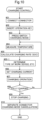
- the operator In response to charging the travel battery 4, the operator connects the power supply connector 36 of the power supply device KD to the charging connection portion 37. Next, in the switching operation portion 44 provided on the operation panel 43 of the driving section 3, the operation key 45 is inserted into and attached to the insertion portion 46, and the switch 47 is pressed. When the control device 34 recognizes this, the control device 34 switches to the charging mode (steps #101, #102, #103).
- step # 104 Upon being switched to the charging mode, the operation of the electric motor M is restrained by stopping the output of the inverter 14 (step # 104). Next, necessary information is transmitted via the charging communication harness 49 so as to supply power to the power supply device KD, and the power supply device KD starts charging the travel battery 4 (step #105).
- the travel battery 4 is charged to a preset charging state, and when a fully-charged state is reached, charging is stopped (steps #106 and #107).
- step #108 it is determined whether or not the operation key 45 has been inserted into the insertion portion 46 (step #108). At that time, if it is determined that the operation key 45 has been removed and is not attached, it is assumed that the operation key 45 was removed and taken by the driver while charging was being performed, and therefore the control device 34 is switched to the non-operating state and the power supply is mandatorily cut off (step #109).
- control device 34 will automatically switch to the non-operating state in response to charging being completed.
- step #108, #110, #111 the output of the inverter 14 is restarted to enable the electric motor M to operate, thereby canceling the operation restrained state of the electric motor M (step #112). Accordingly, while the travel battery 4 is being charged, the electric motor M is not activated even if an operation for causing the vehicle to travel is performed, and the vehicle is prohibited from performing movement travel.
- the control device 34 switches to the charging mode upon being switched to the operable state while the power supply connector 36 is connected to the charging connection portion 37. Then, in the charging mode, the travel battery 4 is charged by the power supply device KD.
- the control device 34 prohibits movement travel of the body during a charging operation in the period from when charging of the travel battery 4 with the power supply device KD is started while the power supply connector 36 is connected to the charging connection portion 37, until when the charging of the travel battery 4 is completed. Specifically, the control device 34 does not drive the electric motor M during the charging operation.
- the control device 34 continues charging by the power supply device KD even if the operation key 45 is removed from the insertion portion 46 after starting charging by the power supply device KD. Also, if the control device 34 continues performing charging by the power supply device KD after the operation key 45 is removed from the insertion portion 46, the control device 34 automatically switches to the non-operating state in response to charging being completed.
- the operator In response to charging the travel battery 4, the operator connects the power supply connector 36 of the power supply device KD to the charging connection portion 37. Next, in the switching operation portion 44 provided on the operation panel 43 of the driving section 3, the operation key 45 is inserted into and attached to the insertion portion 46, and the switch 47 is pressed. Upon recognizing this, the control device 34 switches to the charging mode (steps #201, #202, #203).
- step #204 Upon being switched to the charging mode, the operation of the electric motor M is restrained by stopping the output of the inverter 14 (step #204). Next, necessary information is transmitted via the charging communication harness 49 so as to supply power to the power supply device KD, and the power supply device KD starts charging the travel battery 4 (step #205).
- the travel battery 4 is charged to a preset charging state, and in response to reaching a fully-charged state, charging is stopped (steps #206, #207).
- step #208 it is determined whether or not the operation key 45 has been inserted into the insertion portion 46 (step #208). At that time, if it is determined that the operation key 45 has been removed and is not attached, it is assumed that the operation key 45 was removed and taken by the driver while charging was being performed, and therefore the control device 34 is switched to the non-operating state and the power supply is mandatorily cut off (step #209).
- control device 34 will automatically switch to the non-operating state in response to charging being completed.
- the operator disconnects the power supply connector 36 of the power supply device KD to disconnect from the charging connection portion 37, and thereafter presses the switch 47, whereupon the charging mode is canceled (steps #208, #210, #211).
- the output of the inverter 14 is restarted to enable the electric motor M to operate, thereby canceling the operation restrained state of the electric motor M (step #212). Accordingly, while the travel battery 4 is being charged, the electric motor M is not activated even if an operation for causing the vehicle to travel is performed, and the vehicle is prohibited from performing movement travel.
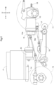
- a travel clutch 250 capable of interrupting the motive power is provided in the transmission path for transmitting the motive power of the electric motor M to the hydraulic continuously variable transmission 15
- a first work clutch 251 capable of interrupting the motive power is provided in the transmission path for transmitting the motive power of the electric motor M to the middle PTO shaft 17
- a second work clutch 252 capable of interrupting the motive power is provided in the transmission path for transmitting the motive power of the electric motor M to the rear PTO shaft 18.
- the control device 34 controls the operation of each of the travel clutch 250, the first work clutch 251, and the second work clutch 252.
- a clutch is generally not provided since the travel stop state can be realized by the neutral position, but in this embodiment, the above-mentioned travel clutch 250 is provided and the control device 34 normally sets the travel clutch 250 to the engaged state, and even if a command to engage the travel clutch 250 is issued during a charging operation, the control device 34 maintains the travel clutch 250 in the disengaged state and prohibits movement of the body by not switching to the clutch-engaged state.
- each of the first work clutch 251 and the second work clutch 252 may be maintained in a clutch-disengaged state.
- a configuration may be used in which only one of the first work clutch 251 and the second work clutch 252 is provided, or a configuration may be used in which neither of the work clutches is provided.
- the operation key 45 can be inserted into the insertion portion 46, but instead of this configuration, the operation key 45 can be connected wirelessly to a reception unit in the body, and the control device 34 may switch to the operable state in response to the switch 47 being operated while the operation key 45 is close to the body.
- control device 34 switched to the charging mode upon being switched to the operable state while the power supply connector 36 was connected to the charging connection portion 37, but instead of this configuration, the control device 34 may be switched to the operable state in advance, and thereafter the control device 34 may switch to the charging mode in response to the power supply connector 36 being connected to the charging connection portion 37.
- the present invention is applicable not only to tractors but also to various electric work vehicles such as rice transplanters, combines, and construction machinery.
Landscapes
- Engineering & Computer Science (AREA)
- Power Engineering (AREA)
- Transportation (AREA)
- Mechanical Engineering (AREA)
- Life Sciences & Earth Sciences (AREA)
- Sustainable Development (AREA)
- Sustainable Energy (AREA)
- Chemical & Material Sciences (AREA)
- Combustion & Propulsion (AREA)
- Charge And Discharge Circuits For Batteries Or The Like (AREA)
- Electric Propulsion And Braking For Vehicles (AREA)
Applications Claiming Priority (4)
| Application Number | Priority Date | Filing Date | Title |
|---|---|---|---|
| JP2021214401A JP7509743B2 (ja) | 2021-12-28 | 2021-12-28 | 電動作業車 |
| JP2021214399A JP7507742B2 (ja) | 2021-12-28 | 2021-12-28 | 電動作業車 |
| JP2021214400A JP7519984B2 (ja) | 2021-12-28 | 2021-12-28 | 電動作業車 |
| PCT/JP2022/043492 WO2023127363A1 (fr) | 2021-12-28 | 2022-11-25 | Engin de chantier électrique |
Publications (2)
| Publication Number | Publication Date |
|---|---|
| EP4458608A1 true EP4458608A1 (fr) | 2024-11-06 |
| EP4458608A4 EP4458608A4 (fr) | 2026-03-04 |
Family
ID=86998864
Family Applications (1)
| Application Number | Title | Priority Date | Filing Date |
|---|---|---|---|
| EP22915594.0A Pending EP4458608A4 (fr) | 2021-12-28 | 2022-11-25 | Engin de chantier électrique |
Country Status (3)
| Country | Link |
|---|---|
| US (1) | US20240308389A1 (fr) |
| EP (1) | EP4458608A4 (fr) |
| WO (1) | WO2023127363A1 (fr) |
Family Cites Families (16)
| Publication number | Priority date | Publication date | Assignee | Title |
|---|---|---|---|---|
| JP2008054442A (ja) * | 2006-08-25 | 2008-03-06 | Honda Motor Co Ltd | 小型電動車両 |
| JP5696377B2 (ja) * | 2010-06-11 | 2015-04-08 | トヨタ自動車株式会社 | 車両用制御装置および車両用制御方法 |
| JP5592857B2 (ja) * | 2011-09-16 | 2014-09-17 | 株式会社クボタ | 作業車 |
| JP5797776B2 (ja) * | 2011-12-28 | 2015-10-21 | 川崎重工業株式会社 | 電動二輪車及びその制御装置の動作方法 |
| JP5970953B2 (ja) * | 2012-05-16 | 2016-08-17 | 日産自動車株式会社 | 車両用ブレーキ制御装置、車両用ブレーキ制御方法 |
| JP5642318B1 (ja) * | 2013-08-02 | 2014-12-17 | 株式会社小松製作所 | 作業車両 |
| JP2015171208A (ja) * | 2014-03-06 | 2015-09-28 | 株式会社豊田自動織機 | 充電システムの制御方法 |
| KR101755798B1 (ko) * | 2015-06-30 | 2017-07-07 | 현대자동차주식회사 | 친환경 차량의 배터리 충방전량 제어 장치 및 방법 |
| JP6523927B2 (ja) * | 2015-11-16 | 2019-06-05 | 株式会社クボタ | 電動作業車両用バッテリパック及び電動作業車両 |
| JP6790617B2 (ja) * | 2016-09-07 | 2020-11-25 | 三菱自動車工業株式会社 | 電動車両 |
| CN109196874B (zh) * | 2016-10-12 | 2022-03-25 | 株式会社久保田 | 作业机的通讯系统 |
| KR102518974B1 (ko) * | 2018-08-21 | 2023-04-06 | 두산산업차량 주식회사 | 배터리 온도에 따른 차량 모터 제어장치 및 방법 |
| JP7304750B2 (ja) | 2019-06-24 | 2023-07-07 | 株式会社クボタ | 電動作業車 |
| WO2021085440A1 (fr) * | 2019-10-31 | 2021-05-06 | 株式会社デンソー | Dispositif de commande de véhicule |
| JP7453834B2 (ja) * | 2020-04-02 | 2024-03-21 | 株式会社Subaru | 車両 |
| US20210316713A1 (en) * | 2020-04-09 | 2021-10-14 | Deere & Company | System and method for runtime planning of an electric battery powered work vehicle |
-
2022
- 2022-11-25 EP EP22915594.0A patent/EP4458608A4/fr active Pending
- 2022-11-25 WO PCT/JP2022/043492 patent/WO2023127363A1/fr not_active Ceased
-
2024
- 2024-05-31 US US18/679,599 patent/US20240308389A1/en active Pending
Also Published As
| Publication number | Publication date |
|---|---|
| US20240308389A1 (en) | 2024-09-19 |
| EP4458608A4 (fr) | 2026-03-04 |
| WO2023127363A1 (fr) | 2023-07-06 |
Similar Documents
| Publication | Publication Date | Title |
|---|---|---|
| US11433771B2 (en) | Electric travelling vehicle and grass mower | |
| JP7825667B2 (ja) | 電動作業車 | |
| US10717361B2 (en) | Work vehicle and display device for the work vehicle | |
| US20130197734A1 (en) | Uncertified battery replacement countermeasure apparatus for electric vehicle | |
| EP3401153A1 (fr) | Véhicule de travail électrique | |
| JP2021099086A (ja) | 作業機 | |
| WO2022270010A1 (fr) | Machine de travail électrique et système de charge pour machine de travail électrique | |
| JP2024120921A5 (fr) | ||
| US12311769B2 (en) | Work vehicle | |
| EP3960523A1 (fr) | Engin de travail | |
| US10816063B2 (en) | Work vehicle having implement | |
| JP6603085B2 (ja) | 車両用電源装置及び車両制御装置 | |
| US20250178457A1 (en) | Electric work vehicle | |
| EP4458608A1 (fr) | Engin de chantier électrique | |
| US20250360896A1 (en) | Work vehicle | |
| JP6628616B2 (ja) | プラグインハイブリッド作業車 | |
| JP2019073147A (ja) | 電動作業機 | |
| JP7519984B2 (ja) | 電動作業車 | |
| JP7507742B2 (ja) | 電動作業車 | |
| US20240100992A1 (en) | Vehicular control system with battery failsafe for driver handover process | |
| EP4475377A1 (fr) | Engin électrique de chantier | |
| JP2024025397A (ja) | 充電システム及び充電方法 | |
| US20240059178A1 (en) | Electric work vehicle | |
| US20240181890A1 (en) | Battery pack auto sensing and switching | |
| JP2026001607A (ja) | 電動作業車両 |
Legal Events
| Date | Code | Title | Description |
|---|---|---|---|
| STAA | Information on the status of an ep patent application or granted ep patent |
Free format text: STATUS: THE INTERNATIONAL PUBLICATION HAS BEEN MADE |
|
| PUAI | Public reference made under article 153(3) epc to a published international application that has entered the european phase |
Free format text: ORIGINAL CODE: 0009012 |
|
| STAA | Information on the status of an ep patent application or granted ep patent |
Free format text: STATUS: REQUEST FOR EXAMINATION WAS MADE |
|
| 17P | Request for examination filed |
Effective date: 20240516 |
|
| AK | Designated contracting states |
Kind code of ref document: A1 Designated state(s): AL AT BE BG CH CY CZ DE DK EE ES FI FR GB GR HR HU IE IS IT LI LT LU LV MC ME MK MT NL NO PL PT RO RS SE SI SK SM TR |
|
| DAV | Request for validation of the european patent (deleted) | ||
| DAX | Request for extension of the european patent (deleted) | ||
| RIC1 | Information provided on ipc code assigned before grant |
Ipc: B60L 58/24 20190101AFI20251105BHEP Ipc: B60L 3/00 20190101ALI20251105BHEP Ipc: B60L 15/20 20060101ALI20251105BHEP Ipc: B60L 50/60 20190101ALI20251105BHEP Ipc: B60L 53/14 20190101ALI20251105BHEP Ipc: B60L 58/10 20190101ALI20251105BHEP Ipc: B62D 49/00 20060101ALI20251105BHEP Ipc: H02J 7/00 20060101ALI20251105BHEP Ipc: H02J 7/04 20060101ALI20251105BHEP Ipc: B60L 1/00 20060101ALI20251105BHEP Ipc: B60L 3/06 20060101ALI20251105BHEP Ipc: B60L 15/10 20060101ALI20251105BHEP Ipc: B60L 53/66 20190101ALI20251105BHEP |
|
| A4 | Supplementary search report drawn up and despatched |
Effective date: 20260202 |
|
| RIC1 | Information provided on ipc code assigned before grant |
Ipc: B60L 58/24 20190101AFI20260127BHEP Ipc: B60L 3/00 20190101ALI20260127BHEP Ipc: B60L 15/20 20060101ALI20260127BHEP Ipc: B60L 50/60 20190101ALI20260127BHEP Ipc: B60L 53/14 20190101ALI20260127BHEP Ipc: B60L 58/10 20190101ALI20260127BHEP Ipc: B62D 49/00 20060101ALI20260127BHEP Ipc: H02J 7/00 20060101ALI20260127BHEP Ipc: H02J 7/04 20060101ALI20260127BHEP Ipc: B60L 1/00 20060101ALI20260127BHEP Ipc: B60L 3/06 20060101ALI20260127BHEP Ipc: B60L 15/10 20060101ALI20260127BHEP Ipc: B60L 53/66 20190101ALI20260127BHEP |