EP4459062A1 - Permanente schalung - Google Patents
Permanente schalung Download PDFInfo
- Publication number
- EP4459062A1 EP4459062A1 EP24168634.4A EP24168634A EP4459062A1 EP 4459062 A1 EP4459062 A1 EP 4459062A1 EP 24168634 A EP24168634 A EP 24168634A EP 4459062 A1 EP4459062 A1 EP 4459062A1
- Authority
- EP
- European Patent Office
- Prior art keywords
- formwork
- concrete
- connecting elements
- sockets
- pipes
- Prior art date
- Legal status (The legal status is an assumption and is not a legal conclusion. Google has not performed a legal analysis and makes no representation as to the accuracy of the status listed.)
- Pending
Links
Images




Classifications
-
- E—FIXED CONSTRUCTIONS
- E04—BUILDING
- E04B—GENERAL BUILDING CONSTRUCTIONS; WALLS, e.g. PARTITIONS; ROOFS; FLOORS; CEILINGS; INSULATION OR OTHER PROTECTION OF BUILDINGS
- E04B2/00—Walls, e.g. partitions, for buildings; Wall construction with regard to insulation; Connections specially adapted to walls
- E04B2/84—Walls made by casting, pouring, or tamping in situ
- E04B2/86—Walls made by casting, pouring, or tamping in situ made in permanent forms
-
- E—FIXED CONSTRUCTIONS
- E04—BUILDING
- E04B—GENERAL BUILDING CONSTRUCTIONS; WALLS, e.g. PARTITIONS; ROOFS; FLOORS; CEILINGS; INSULATION OR OTHER PROTECTION OF BUILDINGS
- E04B1/00—Constructions in general; Structures which are not restricted either to walls, e.g. partitions, or floors or ceilings or roofs
- E04B1/18—Structures comprising elongated load-supporting parts, e.g. columns, girders, skeletons
- E04B1/19—Three-dimensional [3D] framework structures
- E04B1/1903—Connecting nodes specially adapted therefor
- E04B1/1912—Connecting nodes specially adapted therefor with central cubical connecting element
-
- E—FIXED CONSTRUCTIONS
- E04—BUILDING
- E04B—GENERAL BUILDING CONSTRUCTIONS; WALLS, e.g. PARTITIONS; ROOFS; FLOORS; CEILINGS; INSULATION OR OTHER PROTECTION OF BUILDINGS
- E04B2/00—Walls, e.g. partitions, for buildings; Wall construction with regard to insulation; Connections specially adapted to walls
- E04B2/84—Walls made by casting, pouring, or tamping in situ
- E04B2/86—Walls made by casting, pouring, or tamping in situ made in permanent forms
- E04B2/8635—Walls made by casting, pouring, or tamping in situ made in permanent forms with ties attached to the inner faces of the forms
-
- E—FIXED CONSTRUCTIONS
- E02—HYDRAULIC ENGINEERING; FOUNDATIONS; SOIL SHIFTING
- E02B—HYDRAULIC ENGINEERING
- E02B3/00—Engineering works in connection with control or use of streams, rivers, coasts, or other marine sites; Sealings or joints for engineering works in general
- E02B3/04—Structures or apparatus for, or methods of, protecting banks, coasts, or harbours
- E02B3/06—Moles; Piers; Quays; Quay walls; Groynes; Breakwaters ; Wave dissipating walls; Quay equipment
-
- E—FIXED CONSTRUCTIONS
- E04—BUILDING
- E04B—GENERAL BUILDING CONSTRUCTIONS; WALLS, e.g. PARTITIONS; ROOFS; FLOORS; CEILINGS; INSULATION OR OTHER PROTECTION OF BUILDINGS
- E04B1/00—Constructions in general; Structures which are not restricted either to walls, e.g. partitions, or floors or ceilings or roofs
- E04B1/18—Structures comprising elongated load-supporting parts, e.g. columns, girders, skeletons
- E04B1/19—Three-dimensional [3D] framework structures
- E04B1/1903—Connecting nodes specially adapted therefor
- E04B1/1912—Connecting nodes specially adapted therefor with central cubical connecting element
- E04B2001/1915—Connecting nodes specially adapted therefor with central cubical connecting element with strut engaging means at the edges of the cube
-
- E—FIXED CONSTRUCTIONS
- E04—BUILDING
- E04B—GENERAL BUILDING CONSTRUCTIONS; WALLS, e.g. PARTITIONS; ROOFS; FLOORS; CEILINGS; INSULATION OR OTHER PROTECTION OF BUILDINGS
- E04B1/00—Constructions in general; Structures which are not restricted either to walls, e.g. partitions, or floors or ceilings or roofs
- E04B1/18—Structures comprising elongated load-supporting parts, e.g. columns, girders, skeletons
- E04B1/19—Three-dimensional [3D] framework structures
- E04B1/1903—Connecting nodes specially adapted therefor
- E04B2001/1921—Connecting nodes specially adapted therefor with connecting nodes having radial connecting stubs
-
- E—FIXED CONSTRUCTIONS
- E04—BUILDING
- E04B—GENERAL BUILDING CONSTRUCTIONS; WALLS, e.g. PARTITIONS; ROOFS; FLOORS; CEILINGS; INSULATION OR OTHER PROTECTION OF BUILDINGS
- E04B1/00—Constructions in general; Structures which are not restricted either to walls, e.g. partitions, or floors or ceilings or roofs
- E04B1/18—Structures comprising elongated load-supporting parts, e.g. columns, girders, skeletons
- E04B1/19—Three-dimensional [3D] framework structures
- E04B2001/1924—Struts specially adapted therefor
- E04B2001/1927—Struts specially adapted therefor of essentially circular cross section
-
- E—FIXED CONSTRUCTIONS
- E04—BUILDING
- E04B—GENERAL BUILDING CONSTRUCTIONS; WALLS, e.g. PARTITIONS; ROOFS; FLOORS; CEILINGS; INSULATION OR OTHER PROTECTION OF BUILDINGS
- E04B1/00—Constructions in general; Structures which are not restricted either to walls, e.g. partitions, or floors or ceilings or roofs
- E04B1/18—Structures comprising elongated load-supporting parts, e.g. columns, girders, skeletons
- E04B1/19—Three-dimensional [3D] framework structures
- E04B2001/1957—Details of connections between nodes and struts
-
- E—FIXED CONSTRUCTIONS
- E04—BUILDING
- E04B—GENERAL BUILDING CONSTRUCTIONS; WALLS, e.g. PARTITIONS; ROOFS; FLOORS; CEILINGS; INSULATION OR OTHER PROTECTION OF BUILDINGS
- E04B1/00—Constructions in general; Structures which are not restricted either to walls, e.g. partitions, or floors or ceilings or roofs
- E04B1/18—Structures comprising elongated load-supporting parts, e.g. columns, girders, skeletons
- E04B1/19—Three-dimensional [3D] framework structures
- E04B2001/1981—Three-dimensional [3D] framework structures characterised by the grid type of the outer planes of the framework
- E04B2001/1984—Three-dimensional [3D] framework structures characterised by the grid type of the outer planes of the framework rectangular, e.g. square, grid
-
- E—FIXED CONSTRUCTIONS
- E04—BUILDING
- E04B—GENERAL BUILDING CONSTRUCTIONS; WALLS, e.g. PARTITIONS; ROOFS; FLOORS; CEILINGS; INSULATION OR OTHER PROTECTION OF BUILDINGS
- E04B1/00—Constructions in general; Structures which are not restricted either to walls, e.g. partitions, or floors or ceilings or roofs
- E04B1/18—Structures comprising elongated load-supporting parts, e.g. columns, girders, skeletons
- E04B1/19—Three-dimensional [3D] framework structures
- E04B2001/1981—Three-dimensional [3D] framework structures characterised by the grid type of the outer planes of the framework
- E04B2001/1987—Three-dimensional [3D] framework structures characterised by the grid type of the outer planes of the framework triangular grid
Definitions
- the invention relates to the field of construction, namely to formwork and is a scalable, modular, periodic, permanent beam-node formwork for casting reinforced concrete, including underwater, and forming flat and volumetric concrete structures, including trusses isolated from corrosive effects of the external environment.
- a block of a permanent formwork including formwork plates connected to a spatial reinforcing lattice frame made of tubular elements, and the lattice units - in the form of spherical elements connected to the formwork plates, in which sockets with internal threads are formed, and the tubes are provided with tips located along their longitudinal axis with a threaded cantilever protrusion for placement in receptacles of spherical elements ( RU 2029840 C1, published 27.02.1995 ).
- a permanent decorative formwork representing a spatially positioned flat elements limiting at least a part of the outer contour of the manufactured object, wherein these flat elements are bonded to each other to form a space between these elements for placing fittings and filling with a fluid-flowing material capable of solidification, wherein these flat elements are made of sheet steel and represent fragments of the external contour of the manufactured object, part of which is made fastenable to fittings to form part of the surface of the manufactured object after solidification of the fluid-flowing material ( RU 138426 U1, published 20.03.2014 ).
- a formwork comprising a form-forming flexible support shell in the form of a closed awning, the base of which is laid on a deck mounted on auxiliary beams, and the upper forming part of the awning is made with a relief surface corresponding to the formed structure and comprising intersecting channels for reinforcement of ribs installed in them to form a honeycomb surface of the structure ( RU 2737744 C1, published 02.12.2020 ).
- One of the technical problems solved by the proposed invention is to create a formwork system that allows to provide a concrete product with optimal wave and corrosion resistance .
- 3D truss which is an optimal construction (base) in terms of strength/material consumption and strength/cost ratios for underwater parts of most hydraulic structures.
- An open 3D truss also provides minimal resistance to waves and does not lead to erosion of the bottom soil.
- the proposed technical solution provides the possibility of a sealed connection (or several connections), incl. at lower points of the cast cavity to the concrete pump, by means of a concrete pipeline, which allows for pressure casting of concrete "from below upwards " at a distance of up to 80 meters from the coast line, with minimal human participation.
- the technical result of the patented formwork is the possibility of using it for the construction of reinforced concrete 3D trusses in the tidal zone and underwater in coastal areas of water reservoirs (from 1 to 12 meters deep) by eliminating deformations when filling the formwork with concrete and during operation, as well as by insulating concrete from the corrosive effects of salt water, biological destruction.
- the shell of the proposed formwork also significantly reduces the adhesion of concrete to ice, which significantly increases the operation life of concrete products in conditions of the sea or freezing water reservoirs.
- the proposed technical result is provided by the construction of a permanent formwork, including nodal connecting elements and pipes, wherein the nodal connecting elements are made in the form of hollow volumetric bodies with sockets oriented at angles to each other, some of which are plugged, and pipes are installed in others.
- the formwork includes external shafts made of metal or composite bars installed in the sockets of the nodal connecting elements at an angle to the sockets with pipes.
- At least one socket of the nodal connecting element is made with the possibility to be connected to a concrete pump for filling the formwork with concrete.
- the formwork includes reusable removable frames fixed on nodal connecting elements.
- the nodal connecting elements are made of polyethylene or PVC, or polypropylene, or metal, or fiberglass.
- as pipes are used water or gas or sewer tubes.
- the pipes are made of polyethylene or PVC, or polypropylene, or metal, or fiberglass.
- the pipes are fixed in the sockets of a nodal connecting element by welding or tube-locking, or gluing, or a spigot and socket connection, or fixing by screws, anchors, or rivets.
- At least one pipe is made with a window in its wall.
- the sockets of the nodal connecting elements are arranged coaxially with the possibility of a through placement of pipes.
- the sockets of the nodal connecting elements are arranged coaxially with the possibility of a through placement of shafts.
- the construction of the described formwork allows to create an open 3D concrete truss by forming a cavity for filling with concrete, including hollow pipes and hollow nodal connecting elements, which in the final product perform the function of a shell protecting the concrete truss from interaction with the environment (water, ice, pollution, etc.), thereby preventing the destruction of the structure.
- all openings in the NCE are plugged and openings are drilled only in those sockets where pipes, rods are inserted, or where a concrete pump is connected to.
- Unused openings (sockets) in the NCE remain plugged in order to preserve the tightness of the mold.
- the proposed permanent formwork is designed for creation of an underwater reinforced concrete 3D truss for structures in coastal water areas.
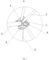
- the structure ready to be filled with concrete, includes polymer nodal connecting elements (NCE) 1, hollow polymer pipes 2 ( FIG. 1 , 3D-model 1).
- Hollow pipes are made of polyethylene or PVC or polypropylene or metal (stainless or galvanized steel or aluminum) or fiberglass, and are usually widely available water or gas or fecal pipes.
- the formwork may include shafts 3 made of metal or composite materials (bars), the shafts are not filled with concrete and play the role of external reinforcement, the diameter of the shafts in the range of 12-40 mm allows to withstand a tensile force of up to 150 tons, with a weight of 200-900 g per linear meter, providing the finished 3D truss with spatial rigidity.
- bars metal or composite materials
- the structure is beam-angular, all pipes 2 and straight shafts 3 in the structure begin and end at the nodal connecting elements 1.
- console pipes can be used that go beyond the dimensions of the 3D truss, and L-shaped shafts that start with a straight end in the fitting, and a bent one fixed at any point on the pipe.
- the nodal connecting element is a hollow volumetric body with sockets 4 oriented at different angles to each other (30°, 60°, 45°, 90°), and also opposite from different sides of the element (coaxially) with openings providing through passage of the pipe through the openings in the sockets.
- the nodal connecting elements are made of polyethylene or PVC or polypropylene or metal (stainless or galvanized steel or aluminum) or fiberglass.
- the nodal connecting elements are made with plugged sockets 4 and 5, and some of them, for installing pipes 2 and shafts 3 in them, are drilled by installers during assembly in various combinations, depending on the position of the fitting in the structure or the desired mechanical load on the structure, to ensure complete retention of concrete in the formwork, without leakage through unused openings.
- the pipes 2 can be fixed in the openings of the sockets 4 of the nodal connecting element by welding or tube-locking and/or gluing and/or a spigot and socket connection and/or fixing by screws, anchors, rivets or by means of through passage of the pipe through the nodal connecting element with a window in the pipe wall or without a window.
- the nodal connecting elements are made with a socket 6, to which a concrete pump is connected by means of a concrete pipeline.
- any nodal connecting element in the lower (bottom) part of the formwork is used.
- Nodal connecting elements may have fixing units for external removable (reusable) reinforcement of the formwork structure in order to prevent deformation or destruction of the structure at the time of filling with fresh (liquid) concrete.
- the specified reinforcement for example, wooden frames
- the specified reinforcement is disassembled and reused on another structure, after setting the concrete and gaining a minimum calculated strength.
- the nodal connecting elements may have the same design, which can be used for all units of the structure.
- each set can include from 1 to 4 nodal connecting elements.
- the proposed formwork is scalable, the basic distance between adjacent nodal elements of the structure can be selected by the user arbitrarily and in a wide range due to the possibility of open-ended installation of pipes in nodal elements.
- the selection of the length of the basic pipe(s) automatically sets the length of all other pipes.
- changing the cell size of the structure does not require an additional range of specialized formwork elements (as in most known prior art), but influences only the cutting of the pipes.
- nodal connecting element For assembling a plurality of different structures, only few models of nodal connecting elements (or one) will be required, which will be repeated many times in the units of the structure.
- the nodal connecting element has an excessive number of ports (sockets) for connecting pipes and shafts, which allows it to be used in truss units with a different required set of pipes (angle, face, side surface, etc.).
- the formwork structure is periodic, the angles between the pipes 2 in several adjacent nodal connecting elements (usually six or eight elements) set the shape of an elementary volumetric cell of the structure, which will be repeated many times in different directions. Therein, all (or part of) adjacent cells will be equally sized, and the other part will be proportionally sized (each subsequent cell is proportionally larger or smaller than the previous one).
- Example 1 construction of rail slips (wedge winch boatlifts) or roller ramps.
- the structure consists of two half-trusses, one above the other.
- the lower half-truss ( FIG. 4 , 3D model No. 2) is an inclined (18°) trapezoid that sets the slope of the entire ramp. If the slope of the ramp is not required (the bottom relief has a slope), it is possible to completely abandon the lower half-truss (or replace it with bored piles).
- the main advantages of slips and ramps built using the proposed technology are the following. Imperceptibility of the structure by bottom sediments, saving concrete, durability.
- the structures are adapted to tides with an amplitude of up to 150 cm.
- the working depth difference (reachable for trolley) is up to 3 meters.
- the fitting system is designed for ramp lifting/launching of watercrafts, without a trolley - on rollers. Designed for jet skis, motorboats or dinghies.
- a manual or electric winch with a pulling force of not less than 50% of the weight of the watercraft, for comfortable lifting of the watercraft onto the ramp and its fixation.
- the working (inter-roller) width of the ramp is set during installation, in accordance with watercrafts intended to be used.
- the ramp is mounted on reliable (including stepped) bases, subject to the angle of inclination of the ramp.
- the structure does not have horizontal transverse or diagonal beams in the upper tier of fittings, which ensures compatibility with PWC V-hulls and boats.
- Each fitting has two U-shaped attachment points for a thick-walled "roller” pipe with a diameter of 65 mm with the possibility of axial rotation.
- a concrete pipe flange is provided in each fitting.
- roller pipe On the roller pipe can be mounted in pairs soft plastic rollers with a diameter of 150-200 mm (not less than 3 pairs per fitting in the upper tier of the ramp).
- the rollers must have a "floating" angle of ascent adapted to the lines of the boat's hull.
- the external reinforcement is carried out by means of L-shaped edged shafts, it allows adjusting the length of the shafts "in place", and as a “hinge” attachment point, using an opening in any place of the pipe beam anchoring the curved end of the shaft. Therein, the straight (shortened) end is fixed in a standard socket on the fitting. This ensures the functionality of the shafts (the presence of sufficient leverage and compliance with the direction of load perception) at their low cost and complete versatility.
- the system is assembled from polypropylene pipes with an outer diameter of 400 mm and 100 mm, as well as polypropylene NCE.
- Example 2 - formwork for the manufacture of reinforced concrete keel blocks for sailing yachts, dinghies or boats (FIG. 5, 3D model No. 3).
- the monofitting used in the system is suitable for the manufacture of support (BUNK) keel blocks, with a soft adjustable stop (fender), and locking (SLING) keel blocks, as well as "Swedish” (hook) extensions (for vessels supported on the keel).
- the supporting column has an inclination from the vertical of 15° in the direction “to” or “from” the hull of the vessel.
- Support keel blocks as a rule, have a screw jack or a rubber (including pneumatic) cushion for even distribution of the load between the support points.
- the fitting has an excessive number of interconnections, which allows manufacturing both rectangular keel blocks and "oval" ones (with a different distance between each pair of opposing legs).
- the formwork can be with or without undercarriage (central) supports.
- Each fitting has a built-in concrete pipe flange.
- the system is assembled from metal or composite thick-walled pipes with a diameter of 50 mm (stainless steel for marine water areas; galvanized steel for freshwater areas), metal NCE and composite shafts with a diameter of 30 mm.
- Example 3 - formwork for the construction of surface crossings, bathing platforms, sea terraces and other low-load (pedestrian, recreational) areas above the water ( FIG. 5 ).
- the maximum depth of the water reservoir at the location of the structure - up to 200 cm.
- the water reservoir can be both fresh and marine, but it must not freeze in winter and experience ice breaks.
- the system consists of 2 series of fittings - extreme (180 degree coverage) and middle (360 degree coverage).
- the bottom versions of the fittings have additional horizontal ports with a diameter of 160 mm for concreting.
- the surface version has a platform for screwing internal screw piles and a welded passage with a diameter of 160 for poles and built-in furniture.
- the system is assembled from HDPE or PVC pipes with an outer diameter of 500 mm and 160 mm, metal or composite thick-walled pipes with a diameter of 51 mm (only stainless steel for marine water areas; also allowed is galvanization for freshwater), composite or PVC nodal connecting elements and stainless steel bars with a diameter of 12 mm or composite bars with a diameter of 40 mm.
- a deck it is possible to use hardwood, composite and stainless lattice decking.
Landscapes
- Engineering & Computer Science (AREA)
- Architecture (AREA)
- Physics & Mathematics (AREA)
- Electromagnetism (AREA)
- Civil Engineering (AREA)
- Structural Engineering (AREA)
- Forms Removed On Construction Sites Or Auxiliary Members Thereof (AREA)
Applications Claiming Priority (1)
| Application Number | Priority Date | Filing Date | Title |
|---|---|---|---|
| RU2023111646A RU2813287C1 (ru) | 2023-05-04 | Несъемная опалубка |
Publications (1)
| Publication Number | Publication Date |
|---|---|
| EP4459062A1 true EP4459062A1 (de) | 2024-11-06 |
Family
ID=90789177
Family Applications (1)
| Application Number | Title | Priority Date | Filing Date |
|---|---|---|---|
| EP24168634.4A Pending EP4459062A1 (de) | 2023-05-04 | 2024-04-05 | Permanente schalung |
Country Status (2)
| Country | Link |
|---|---|
| US (1) | US20240368876A1 (de) |
| EP (1) | EP4459062A1 (de) |
Citations (7)
| Publication number | Priority date | Publication date | Assignee | Title |
|---|---|---|---|---|
| CA972977A (en) * | 1972-05-18 | 1975-08-19 | Texaco Development Corporation | Marine structure |
| NL7901012A (nl) * | 1979-02-08 | 1980-08-12 | Continental Oil Co | Werkwijze om korrosie en vermoeidheid ten gevolge van korrosie van verbindingsstukken van stalen konstruk- ties ondergedompeld in zeewater of andere korrosieve media te voorkomen. |
| RU2029840C1 (ru) | 1991-09-30 | 1995-02-27 | Дьяконов Олег Николаевич | Армоопалубочный блок |
| RU2258122C2 (ru) | 1999-04-13 | 2005-08-10 | Энкофрадос Х. Альсина, С.А. | Опалубка для колонн |
| EP2067915A2 (de) * | 2007-12-04 | 2009-06-10 | WeserWind GmbH | Gitterstruktur eines Offshore-Bauwerks, insbesondere einer Offshore-Windenergieanlage |
| RU138426U1 (ru) | 2013-11-28 | 2014-03-20 | Владислав Викторович Богомолов | Несъемная декоративная опалубка из стали (варианты) |
| RU2737744C1 (ru) | 2020-06-15 | 2020-12-02 | федеральное государственное бюджетное образовательное учреждение высшего образования "Хакасский государственный университет им. Н.Ф. Катанова" (ФГБОУ ВО ХГУ им. Н.Ф. Катанова) | Опалубка для железобетонных конструкций и сооружений |
Family Cites Families (7)
| Publication number | Priority date | Publication date | Assignee | Title |
|---|---|---|---|---|
| US3724222A (en) * | 1971-06-10 | 1973-04-03 | G Crain | Mooring structure and method |
| US4245809A (en) * | 1978-08-30 | 1981-01-20 | Jackson Andrew G | Frame-forming method and apparatus |
| USRE33438E (en) * | 1986-06-16 | 1990-11-13 | Lockheed Missiles & Space Company, Inc. | Coupling mechanism |
| DE20208388U1 (de) * | 2002-05-29 | 2002-08-14 | Pfeiffer, Maria, 97299 Zell | Bausatz zum Errichten von zerlegbaren Bauwerken |
| US7063481B2 (en) * | 2003-08-13 | 2006-06-20 | Trull Scott E | Connector block for modular construction and object fabricated therefrom |
| US9702137B2 (en) * | 2012-02-07 | 2017-07-11 | Mhi Vestas Offshore Wind A/S | Node structures for lattice frames |
| EP3327213A1 (de) * | 2016-11-24 | 2018-05-30 | Jose Ramon Lopez Blanco | Knotenelemente, kit und verfahren zum aufbauen |
-
2024
- 2024-04-05 EP EP24168634.4A patent/EP4459062A1/de active Pending
- 2024-04-08 US US18/628,955 patent/US20240368876A1/en active Pending
Patent Citations (7)
| Publication number | Priority date | Publication date | Assignee | Title |
|---|---|---|---|---|
| CA972977A (en) * | 1972-05-18 | 1975-08-19 | Texaco Development Corporation | Marine structure |
| NL7901012A (nl) * | 1979-02-08 | 1980-08-12 | Continental Oil Co | Werkwijze om korrosie en vermoeidheid ten gevolge van korrosie van verbindingsstukken van stalen konstruk- ties ondergedompeld in zeewater of andere korrosieve media te voorkomen. |
| RU2029840C1 (ru) | 1991-09-30 | 1995-02-27 | Дьяконов Олег Николаевич | Армоопалубочный блок |
| RU2258122C2 (ru) | 1999-04-13 | 2005-08-10 | Энкофрадос Х. Альсина, С.А. | Опалубка для колонн |
| EP2067915A2 (de) * | 2007-12-04 | 2009-06-10 | WeserWind GmbH | Gitterstruktur eines Offshore-Bauwerks, insbesondere einer Offshore-Windenergieanlage |
| RU138426U1 (ru) | 2013-11-28 | 2014-03-20 | Владислав Викторович Богомолов | Несъемная декоративная опалубка из стали (варианты) |
| RU2737744C1 (ru) | 2020-06-15 | 2020-12-02 | федеральное государственное бюджетное образовательное учреждение высшего образования "Хакасский государственный университет им. Н.Ф. Катанова" (ФГБОУ ВО ХГУ им. Н.Ф. Катанова) | Опалубка для железобетонных конструкций и сооружений |
Also Published As
| Publication number | Publication date |
|---|---|
| US20240368876A1 (en) | 2024-11-07 |
Similar Documents
| Publication | Publication Date | Title |
|---|---|---|
| US6491473B2 (en) | Precast modular concrete shapes and methods of installation to form shoreline stabilization, marine and terrestrial structures | |
| EP3924159B1 (de) | Verfahren zur herstellung eines saugankers | |
| US11920559B2 (en) | Floating platform for high-power wind turbines | |
| US3640075A (en) | Method of installing breakwater caissons | |
| US5713296A (en) | Lightweight concrete dock | |
| KR102368919B1 (ko) | 부력조절이 가능한 콘크리트 폰툰을 이용한 해상 부유식 소파제 | |
| US7007620B2 (en) | Modular ships for transporting and installing precast modular intermodal concrete shapes | |
| US4263862A (en) | Lightweight marine structural concrete system | |
| CN101230558A (zh) | 一种浮式景观斜拉桥 | |
| EP4459062A1 (de) | Permanente schalung | |
| RU2813287C1 (ru) | Несъемная опалубка | |
| US9505468B2 (en) | Floating platform | |
| KR102376885B1 (ko) | 스폰손을 탑재한 코퍼댐의 부력구조 | |
| RU2616378C2 (ru) | Прижимное сегментное устройство для ремонта металлических и бетонных оснований гидротехнических сооружений в подводной зоне и переменном уровне воды | |
| KR102777687B1 (ko) | 내구성이 강화된 콘크리트 단위부체와 이를 이용한 맞춤형 복합 웨일러 마리나 시스템 | |
| CN211810117U (zh) | 分体组合式水上平台 | |
| US3990254A (en) | Marine structure for offshore activities | |
| KR102200448B1 (ko) | 부력 보강용 에어파이프를 갖는 양식장용 부유식 구조물 | |
| NL1023320C2 (nl) | De uitvinding heeft betrekking op een methode voor fabricage, installatie en verwijderen van een offshore platform. | |
| GB2572169A (en) | A float | |
| CN224171139U (zh) | 漂浮式风电平台 | |
| CN218559122U (zh) | 一种基于桩基抱箍悬挑定位的梳齿结构浮式平台 | |
| KR102445095B1 (ko) | 부력조절이 가능한 콘크리트 폰툰을 이용한 해상 부유식 주차장 | |
| JPH0111799Y2 (de) | ||
| CA3125245C (en) | Floating platform for high-power wind turbines |
Legal Events
| Date | Code | Title | Description |
|---|---|---|---|
| PUAI | Public reference made under article 153(3) epc to a published international application that has entered the european phase |
Free format text: ORIGINAL CODE: 0009012 |
|
| STAA | Information on the status of an ep patent application or granted ep patent |
Free format text: STATUS: THE APPLICATION HAS BEEN PUBLISHED |
|
| AK | Designated contracting states |
Kind code of ref document: A1 Designated state(s): AL AT BE BG CH CY CZ DE DK EE ES FI FR GB GR HR HU IE IS IT LI LT LU LV MC ME MK MT NL NO PL PT RO RS SE SI SK SM TR |
|
| STAA | Information on the status of an ep patent application or granted ep patent |
Free format text: STATUS: REQUEST FOR EXAMINATION WAS MADE |
|
| 17P | Request for examination filed |
Effective date: 20250318 |
|
| TPAC | Observations filed by third parties |
Free format text: ORIGINAL CODE: EPIDOSNTIPA |