EP4459072A1 - Aussparungsformer zum giessen einer aussparung in einem betonsegment und verfahren zum giessen einer aussparung in einem betonsegment - Google Patents
Aussparungsformer zum giessen einer aussparung in einem betonsegment und verfahren zum giessen einer aussparung in einem betonsegment Download PDFInfo
- Publication number
- EP4459072A1 EP4459072A1 EP23382420.0A EP23382420A EP4459072A1 EP 4459072 A1 EP4459072 A1 EP 4459072A1 EP 23382420 A EP23382420 A EP 23382420A EP 4459072 A1 EP4459072 A1 EP 4459072A1
- Authority
- EP
- European Patent Office
- Prior art keywords
- recess
- recess former
- concrete segment
- former
- height
- Prior art date
- Legal status (The legal status is an assumption and is not a legal conclusion. Google has not performed a legal analysis and makes no representation as to the accuracy of the status listed.)
- Pending
Links
Images




Classifications
-
- E—FIXED CONSTRUCTIONS
- E04—BUILDING
- E04G—SCAFFOLDING; FORMS; SHUTTERING; BUILDING IMPLEMENTS OR AIDS, OR THEIR USE; HANDLING BUILDING MATERIALS ON THE SITE; REPAIRING, BREAKING-UP OR OTHER WORK ON EXISTING BUILDINGS
- E04G21/00—Preparing, conveying, or working-up building materials or building elements in situ; Other devices or measures for constructional work
- E04G21/14—Conveying or assembling building elements
- E04G21/142—Means in or on the elements for connecting same to handling apparatus
-
- B—PERFORMING OPERATIONS; TRANSPORTING
- B28—WORKING CEMENT, CLAY, OR STONE
- B28B—SHAPING CLAY OR OTHER CERAMIC COMPOSITIONS; SHAPING SLAG; SHAPING MIXTURES CONTAINING CEMENTITIOUS MATERIAL, e.g. PLASTER
- B28B23/00—Arrangements specially adapted for the production of shaped articles with elements wholly or partly embedded in the moulding material; Production of reinforced objects
- B28B23/005—Arrangements specially adapted for the production of shaped articles with elements wholly or partly embedded in the moulding material; Production of reinforced objects with anchoring or fastening elements for the shaped articles
-
- B—PERFORMING OPERATIONS; TRANSPORTING
- B28—WORKING CEMENT, CLAY, OR STONE
- B28B—SHAPING CLAY OR OTHER CERAMIC COMPOSITIONS; SHAPING SLAG; SHAPING MIXTURES CONTAINING CEMENTITIOUS MATERIAL, e.g. PLASTER
- B28B23/00—Arrangements specially adapted for the production of shaped articles with elements wholly or partly embedded in the moulding material; Production of reinforced objects
- B28B23/0056—Means for inserting the elements into the mould or supporting them in the mould
-
- B—PERFORMING OPERATIONS; TRANSPORTING
- B66—HOISTING; LIFTING; HAULING
- B66C—CRANES; LOAD-ENGAGING ELEMENTS OR DEVICES FOR CRANES, CAPSTANS, WINCHES, OR TACKLES
- B66C1/00—Load-engaging elements or devices attached to lifting or lowering gear of cranes or adapted for connection therewith for transmitting lifting forces to articles or groups of articles
- B66C1/10—Load-engaging elements or devices attached to lifting or lowering gear of cranes or adapted for connection therewith for transmitting lifting forces to articles or groups of articles by mechanical means
- B66C1/62—Load-engaging elements or devices attached to lifting or lowering gear of cranes or adapted for connection therewith for transmitting lifting forces to articles or groups of articles by mechanical means comprising article-engaging members of a shape complementary to that of the articles to be handled
- B66C1/66—Load-engaging elements or devices attached to lifting or lowering gear of cranes or adapted for connection therewith for transmitting lifting forces to articles or groups of articles by mechanical means comprising article-engaging members of a shape complementary to that of the articles to be handled for engaging holes, recesses, or abutments on articles specially provided for facilitating handling thereof
- B66C1/666—Load-engaging elements or devices attached to lifting or lowering gear of cranes or adapted for connection therewith for transmitting lifting forces to articles or groups of articles by mechanical means comprising article-engaging members of a shape complementary to that of the articles to be handled for engaging holes, recesses, or abutments on articles specially provided for facilitating handling thereof for connection to anchor inserts embedded in concrete structures
-
- E—FIXED CONSTRUCTIONS
- E04—BUILDING
- E04G—SCAFFOLDING; FORMS; SHUTTERING; BUILDING IMPLEMENTS OR AIDS, OR THEIR USE; HANDLING BUILDING MATERIALS ON THE SITE; REPAIRING, BREAKING-UP OR OTHER WORK ON EXISTING BUILDINGS
- E04G15/00—Forms or shutterings for making openings, cavities, slits, or channels
- E04G15/04—Cores for anchor holes or the like around anchors embedded in the concrete
Definitions
- the present invention relates to a recess former configured to cast a recess in a concrete segment preferably for carrying out the lifting of the concrete segment.
- the object of the present invention is also an assembly configured to cast a recess in a concrete segment for carrying out the lifting of the concrete segment.
- Another object of the present invention is a method of casting a recess in a concrete segment for carrying out the lifting of the concrete segment.
- Such components include so called lifting anchors which are used to attach lifting equipment to the concrete element.
- One such lifting anchor in widespread use is an elongate substantially planar lifting anchor which is partially embedded into the concrete element.
- the anchor has a through aperture adjacent its free end while the other end which is embedded in the concrete is adapted to form a mechanical interlock with the concrete of the element in which it is embedded or the internal framework of the concrete element.
- the through aperture is shaped to receive lifting means or other attachment device.
- the lifting anchors are embedded in the concrete elements at the time of casting the concrete.
- the free end of the anchor which has the through aperture to receive the lifting anchor is secured in a recess former.
- the recess former is in contact with the formwork or mould used to cast the concrete element. After the concrete has hardened and the mould or formwork is removed, the recess former is itself removed, leaving a recess in the surface of the concrete element such that the attachment end of the anchor is accessible.
- the recess formers of the state of the art do not allow a good fit between the recess former and the countermould, due to the rigidity of the recess former, which sometimes result in a difficult closure of the countermould and, in turn, more concrete is needed to fill the mould completely.
- the recess former of the present invention solves the above-mentioned disadvantage.
- the present invention relates to a recess former which allows the proper formation of a recess in a concrete element, allowing a better closure of the countermould, also reducing the quantity of concrete needed to fill the mould and allowing an easy removal of the recess former from the concrete element once casted.
- the recess former is configured to cast a recess in a concrete segment for carrying out the lifting of the concrete segment, wherein the concrete segment is configured to be casted in a mould comprising at least a base and a countermould, wherein the concrete segment comprises an anchor; and wherein the recess former comprises:
- the recess former offers the possibility of being compressed, in such a way that the countermould closes better thus resulting in a reduction of the concrete used to cast the concrete element since the final geometry of the concrete element is closer to the theoretical one.
- the locking system of the countermould preferably hydraulic, is less stressed.
- the recess former is completely embedded in the concrete or below the level of the surface of the concrete element once casted, facilitating its removal
- the ratio between the first height and the second height is in the interval (1.04-1.17).
- the ratio between the first height and the second height is in the interval (1.08-1.13). More preferably, the ratio between the first height and the second height is 1.09.
- the recess former comprises an elastomeric material, being the elastomeric material preferably a silicone rubber, thus offering good resistance to extreme temperatures, being able to operate normally from -100 to 300 °C.
- the silicone rubber comprises a hardness in the interval (20-35) shore A.
- the silicone rubber comprises a hardness in the interval (25-32) shore A. More preferably, the silicone rubber comprises a hardness of 30 shore A.
- the recess former previously described optionally comprises extraction means configured to extract the recess former from the concrete segment after the concrete segment is casted.
- the recess former can be extracted from the concrete segment once the concrete segment is casted and the countermould has been removed from the mould.
- the extraction means comprise at least one lateral protrusion extending from the second surface, wherein the at least one lateral protrusion is partially coplanar with the first surface.
- the extraction means comprises two lateral protrusions extending from the second surface in opposite directions, wherein the two lateral protrusions are partially coplanar with the first surface.
- the extraction means comprise at least one eyebolt disposed below the first surface.
- the extraction means comprises two eyebolts symmetrically disposed with respect to the opening of the second surface. In this way, the extraction of the recess former can be carried out in an essentially vertical direction.
- the extraction means comprise at least one sling that emerges from the first surface.
- the at least one sling emerges from the first surface through two slots of the recess former symmetrically disposed with respect to the opening of the second surface. In this way, the extraction of the recess former can be carried out in an essentially vertical direction.
- the extraction means comprises at least one through-hole from the first surface to the second surface, where the at least one through-hole is configured to allow the insertion of compressed air.
- the opening of the recess former comprises an upper surface configured, in use, to rest on an upper end of the anchor.
- the upper surface of the recess former is in contact with the second surface.
- the anchor may surpass the second surface on opposite sides of the recess former.
- the upper surface of the recess former is separated from the second surface.
- the upper end of the anchor remains embedded inside the recess former, not surpassing the second surface on opposite sides of the recess former.
- the invention also relates to an assembly configured to cast a recess in a concrete segment for carrying out the lifting of the concrete segment, wherein the assembly comprises:
- the invention also relates to a method of casting a recess in a concrete segment for carrying out the lifting of the concrete segment, wherein the concrete segment is configured to be casted in a mould comprising at least a base and a countermould, wherein the concrete segment comprises an anchor; and wherein the method is carried out with the recess former described above and comprises:
- the step of compression provides a compression of the first height of between 4% and 17%.
- the invention is described in detail as follows. It relates to a recess former (10) configured to cast a recess (50) in a concrete segment (100), preferably for carrying out the lifting of the concrete segment (100), wherein the concrete segment (100) is configured to be casted in a mould comprising at least a base and a countermould (70), wherein the concrete segment (100) comprises an anchor (101); and
- the recess former (10) comprises extraction means (4, 4', 5, 6) configured to extract the recess former (10) from the concrete segment after the concrete segment (100) is casted.
- the opening (3) of the recess former (10) comprises an upper surface (7) configured, in use, to rest on an upper end (102) of the anchor (101).
- the extraction means (4, 4', 5, 6) comprise at least one lateral protrusion (4) extending from the second surface (2), wherein the at least one lateral protrusion (4) is partially coplanar with the first surface (1).
- the extraction means (4, 5, 6) comprises two lateral protrusions (4) extending from the second surface (2) in opposite directions, wherein the two lateral protrusions (4) are partially coplanar with the first surface (1).
- the direction of the two lateral protrusions (4) is perpendicular, in use, to the depth of the recess (50).
- the upper surface (7) of the opening (3) is separated from the second surface (2).
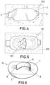
- the upper end (102) of the anchor (101) remains embedded inside the recess former (10), not surpassing the second surface (2) on opposite sides of the recess former (10), as can be seen from Figure 1 together with Figure 2 .
- the two lateral protrusions (4') may be extended in a circumferential way around the second surface (2), as can be seen in Figure 3 .
- the extraction means (6) comprise at least one sling (6) that emerges from the first surface (1), wherein the at least one sling emerges from the first surface (1) through two slots (9) of the recess former (10) symmetrically disposed with respect to the opening (3) of the second surface (2).
- the extraction means (5) comprise at least one eyebolt (5) disposed optionally below the first surface (1).
- the recess former (10) comprises at least one groove (8) carried out in the first surface (1) wherein the at least one eyebolt (5) is disposed.
- the extraction means (5) comprises two eyebolts (5) symmetrically disposed with respect to the opening (3) of the second surface (2).
- the second surface (2) may comprise protrusions (11) centred with the opening (3) and disposed in opposites sides of the second surface. These protrusions (11) optionally allow to extend the opening till the second surface (2) to dispose in the opening an anchor (101) of greater dimensions by reinforcing the recess former (10).
- Figure 8 shows a bottom view of Figure 6 , wherein the opening (3) of the recess former (10) is shown, wherein the upper surface (7) of the opening (3) is separated from the second surface (2).
- the upper end (102) of the anchor (101) remains embedded inside the recess former (10), not surpassing the second surface (2) on opposite sides of the recess former (10).
- the upper surface (7) of the opening (3) may be in contact with the second surface (2).
- the anchor (101) may surpass the second surface (2) on opposite sides of the recess former (10) as shown in Figure 3 .
- protrusions (11) centred with the opening and any of the openings (3) described above may be combined with any of the extraction means, alone or in combination of the embodiments described above.
- the invention also relates to an assembly configured to cast a recess (50) in a concrete segment (100), preferably for carrying out the lifting of the concrete segment (100), wherein assembly comprises:
- Figure 2 shows a scheme of the recess former (10) of the invention before the recess former is compressed by the countermould (70) on the left side and after the recess former (10) has been compressed by the countermould (70) on the right side, following a method of casting a recess (50) in a concrete segment (100), preferably for carrying out the lifting of the concrete segment as can be seen in Figure 9 , wherein the concrete segment (100) is configured to be casted in a mould comprising at least a base and a countermould (70), wherein the concrete segment (100) comprises an anchor (101); and wherein the method is carried out with the recess former (10) described above and comprises:
Landscapes
- Engineering & Computer Science (AREA)
- Architecture (AREA)
- Mechanical Engineering (AREA)
- Manufacturing & Machinery (AREA)
- Chemical & Material Sciences (AREA)
- Ceramic Engineering (AREA)
- Civil Engineering (AREA)
- Structural Engineering (AREA)
- Road Paving Structures (AREA)
Priority Applications (2)
| Application Number | Priority Date | Filing Date | Title |
|---|---|---|---|
| MA71598A MA71598A (fr) | 2023-05-05 | 2023-05-05 | Formeur de évidement configuré pour couler un évidement dans un segment de béton et procédé de coulage d'un évidement dans un segment de béton |
| EP23382420.0A EP4459072A1 (de) | 2023-05-05 | 2023-05-05 | Aussparungsformer zum giessen einer aussparung in einem betonsegment und verfahren zum giessen einer aussparung in einem betonsegment |
Applications Claiming Priority (1)
| Application Number | Priority Date | Filing Date | Title |
|---|---|---|---|
| EP23382420.0A EP4459072A1 (de) | 2023-05-05 | 2023-05-05 | Aussparungsformer zum giessen einer aussparung in einem betonsegment und verfahren zum giessen einer aussparung in einem betonsegment |
Publications (1)
| Publication Number | Publication Date |
|---|---|
| EP4459072A1 true EP4459072A1 (de) | 2024-11-06 |
Family
ID=86330598
Family Applications (1)
| Application Number | Title | Priority Date | Filing Date |
|---|---|---|---|
| EP23382420.0A Pending EP4459072A1 (de) | 2023-05-05 | 2023-05-05 | Aussparungsformer zum giessen einer aussparung in einem betonsegment und verfahren zum giessen einer aussparung in einem betonsegment |
Country Status (2)
| Country | Link |
|---|---|
| EP (1) | EP4459072A1 (de) |
| MA (1) | MA71598A (de) |
Citations (7)
| Publication number | Priority date | Publication date | Assignee | Title |
|---|---|---|---|---|
| EP0262401B1 (de) * | 1986-09-02 | 1990-11-28 | Unistrut Europe PLC | Vorrichtung zur Halterung eines Ankers beim Betonieren eines Betonfertigteiles |
| JPH0847916A (ja) * | 1994-08-04 | 1996-02-20 | Takeda Kogyo Kk | コンクリート製品成形時のアンカー保持具 |
| EP0967347A1 (de) * | 1998-06-25 | 1999-12-29 | G.M. Attrezzature S.r.l. | Methode zur Sicherheitslastverankerung, besonders zum Heben von Betonplatten, und dazugehörige Kupplungsvorrichtung |
| WO2007143784A1 (en) * | 2006-06-13 | 2007-12-21 | Woodstock Percussion Pty Ltd | Recess former for concrete panels |
| US20100011678A1 (en) * | 2008-07-15 | 2010-01-21 | Mimi Management Services Lp | Double anchor and lifting shackle for concrete slabs |
| DE102013019732A1 (de) * | 2013-11-27 | 2015-05-28 | JORDAHL GmbH | Verfahren zur Herstellung von Betonbauteilen mit integrierter Ankerschiene |
| EP3964337A1 (de) * | 2020-09-07 | 2022-03-09 | CRH Structural Concrete Belgium | Verfahren zur herstellung einer betonplatte |
-
2023
- 2023-05-05 EP EP23382420.0A patent/EP4459072A1/de active Pending
- 2023-05-05 MA MA71598A patent/MA71598A/fr unknown
Patent Citations (7)
| Publication number | Priority date | Publication date | Assignee | Title |
|---|---|---|---|---|
| EP0262401B1 (de) * | 1986-09-02 | 1990-11-28 | Unistrut Europe PLC | Vorrichtung zur Halterung eines Ankers beim Betonieren eines Betonfertigteiles |
| JPH0847916A (ja) * | 1994-08-04 | 1996-02-20 | Takeda Kogyo Kk | コンクリート製品成形時のアンカー保持具 |
| EP0967347A1 (de) * | 1998-06-25 | 1999-12-29 | G.M. Attrezzature S.r.l. | Methode zur Sicherheitslastverankerung, besonders zum Heben von Betonplatten, und dazugehörige Kupplungsvorrichtung |
| WO2007143784A1 (en) * | 2006-06-13 | 2007-12-21 | Woodstock Percussion Pty Ltd | Recess former for concrete panels |
| US20100011678A1 (en) * | 2008-07-15 | 2010-01-21 | Mimi Management Services Lp | Double anchor and lifting shackle for concrete slabs |
| DE102013019732A1 (de) * | 2013-11-27 | 2015-05-28 | JORDAHL GmbH | Verfahren zur Herstellung von Betonbauteilen mit integrierter Ankerschiene |
| EP3964337A1 (de) * | 2020-09-07 | 2022-03-09 | CRH Structural Concrete Belgium | Verfahren zur herstellung einer betonplatte |
Non-Patent Citations (1)
| Title |
|---|
| BECHIR H ET AL: "On Poisson's functions of compressible elastomeric materials under compression tests in the framework of linear elasticity theory", ACTA MECHANICA, SPRINGER VIENNA, VIENNA, vol. 230, no. 7, 13 April 2019 (2019-04-13), pages 2491 - 2504, XP036806210, ISSN: 0001-5970, [retrieved on 20190413], DOI: 10.1007/S00707-019-02407-W * |
Also Published As
| Publication number | Publication date |
|---|---|
| MA71598A (fr) | 2025-05-30 |
Similar Documents
| Publication | Publication Date | Title |
|---|---|---|
| RU2496956C2 (ru) | Опалубочное устройство и способ образования углубления при отливке конструктивного элемента | |
| AU2019287193B2 (en) | Ground surface access assemblies | |
| CN206500585U (zh) | 铸造用砂芯紧固装置 | |
| US7108101B1 (en) | Manhole insert for manufacture of a cast member and to provide a step insert having increased structural and holding strength | |
| JPH0375252B2 (de) | ||
| JP2000064794A (ja) | シールドトンネル中仕切り用受けブロック、同受けブロックを使用した中仕切り及びその構築工法 | |
| CN220167192U (zh) | 一种混凝土结构的施工缝结构 | |
| JP4211906B2 (ja) | プレキャスト床版の敷設構造、およびプレキャスト床版の敷設方法 | |
| CN220058565U (zh) | 一种控制钢筋保护层厚度及钢筋间距的装置 | |
| JPH10156517A (ja) | 溶融金属容器の不定形パーマライニングの施工方法 | |
| JP3025596B2 (ja) | コンクリート型枠の間隔保持具 | |
| EP2890850B1 (de) | Verankerungsvorrichtungen für schienenbefestigungsklemmen | |
| JPH0110169Y2 (de) | ||
| US4525902A (en) | Method and means for attaching insulation to a mold | |
| JP3774271B2 (ja) | マッチキャスト製法における埋込み金具の固定方法およびコンクリートブロックの製造方法 | |
| JP4182514B2 (ja) | プレキャストコンクリート壁の形成方法、プレキャストコンクリート壁への配線用ボックスの固定方法、配線空間形成装置及びカバー部材 | |
| CN213269006U (zh) | T形锚固件锚固预留盒 | |
| CN217378981U (zh) | 一种地脚螺栓预留孔套管组件 | |
| CN114761154B (zh) | 用于涂覆钢锅的底部的方法及钢锅的底部 | |
| JP3352807B2 (ja) | 昇降用ステップ付中空体ブロック製造用型枠 | |
| CN120503301A (zh) | 适用于预制构件的钢绞线吊环保护装置及其制备方法 | |
| CN118517147A (zh) | 一种超高层核心筒外围楼板施工缝钢筋预埋及混凝土免凿毛施工方法 | |
| KR200234555Y1 (ko) | 터널 라이닝용 거푸집 | |
| JPH0422967Y2 (de) | ||
| JPH09150239A (ja) | 鋳型押枠 |
Legal Events
| Date | Code | Title | Description |
|---|---|---|---|
| PUAI | Public reference made under article 153(3) epc to a published international application that has entered the european phase |
Free format text: ORIGINAL CODE: 0009012 |
|
| STAA | Information on the status of an ep patent application or granted ep patent |
Free format text: STATUS: THE APPLICATION HAS BEEN PUBLISHED |
|
| AK | Designated contracting states |
Kind code of ref document: A1 Designated state(s): AL AT BE BG CH CY CZ DE DK EE ES FI FR GB GR HR HU IE IS IT LI LT LU LV MC ME MK MT NL NO PL PT RO RS SE SI SK SM TR |
|
| STAA | Information on the status of an ep patent application or granted ep patent |
Free format text: STATUS: REQUEST FOR EXAMINATION WAS MADE |
|
| 17P | Request for examination filed |
Effective date: 20250425 |
|
| RAV | Requested validation state of the european patent: fee paid |
Extension state: MA Effective date: 20250425 |
|
| STAA | Information on the status of an ep patent application or granted ep patent |
Free format text: STATUS: EXAMINATION IS IN PROGRESS |
|
| 17Q | First examination report despatched |
Effective date: 20250909 |