EP4459077A2 - Automatische schwimmbeckenreiniger und komponenten davon - Google Patents
Automatische schwimmbeckenreiniger und komponenten davon Download PDFInfo
- Publication number
- EP4459077A2 EP4459077A2 EP24201102.1A EP24201102A EP4459077A2 EP 4459077 A2 EP4459077 A2 EP 4459077A2 EP 24201102 A EP24201102 A EP 24201102A EP 4459077 A2 EP4459077 A2 EP 4459077A2
- Authority
- EP
- European Patent Office
- Prior art keywords
- track
- swimming pool
- automatic swimming
- pool cleaner
- external surface
- Prior art date
- Legal status (The legal status is an assumption and is not a legal conclusion. Google has not performed a legal analysis and makes no representation as to the accuracy of the status listed.)
- Pending
Links
Images












Classifications
-
- F—MECHANICAL ENGINEERING; LIGHTING; HEATING; WEAPONS; BLASTING
- F04—POSITIVE - DISPLACEMENT MACHINES FOR LIQUIDS; PUMPS FOR LIQUIDS OR ELASTIC FLUIDS
- F04C—ROTARY-PISTON, OR OSCILLATING-PISTON, POSITIVE-DISPLACEMENT MACHINES FOR LIQUIDS; ROTARY-PISTON, OR OSCILLATING-PISTON, POSITIVE-DISPLACEMENT PUMPS
- F04C2/00—Rotary-piston machines or pumps
- F04C2/30—Rotary-piston machines or pumps having the characteristics covered by two or more groups F04C2/02, F04C2/08, F04C2/22, F04C2/24 or having the characteristics covered by one of these groups together with some other type of movement between co-operating members
- F04C2/40—Rotary-piston machines or pumps having the characteristics covered by two or more groups F04C2/02, F04C2/08, F04C2/22, F04C2/24 or having the characteristics covered by one of these groups together with some other type of movement between co-operating members having the movement defined in group F04C2/08 or F04C2/22 and having a hinged member
- F04C2/44—Rotary-piston machines or pumps having the characteristics covered by two or more groups F04C2/02, F04C2/08, F04C2/22, F04C2/24 or having the characteristics covered by one of these groups together with some other type of movement between co-operating members having the movement defined in group F04C2/08 or F04C2/22 and having a hinged member with vanes hinged to the inner member
-
- E—FIXED CONSTRUCTIONS
- E04—BUILDING
- E04H—BUILDINGS OR LIKE STRUCTURES FOR PARTICULAR PURPOSES; SWIMMING OR SPLASH BATHS OR POOLS; MASTS; FENCING; TENTS OR CANOPIES, IN GENERAL
- E04H4/00—Swimming or splash baths or pools
- E04H4/14—Parts, details or accessories not otherwise provided for
- E04H4/16—Parts, details or accessories not otherwise provided for specially adapted for cleaning
- E04H4/1618—Hand-held powered cleaners
- E04H4/1636—Suction cleaners
-
- E—FIXED CONSTRUCTIONS
- E04—BUILDING
- E04H—BUILDINGS OR LIKE STRUCTURES FOR PARTICULAR PURPOSES; SWIMMING OR SPLASH BATHS OR POOLS; MASTS; FENCING; TENTS OR CANOPIES, IN GENERAL
- E04H4/00—Swimming or splash baths or pools
- E04H4/14—Parts, details or accessories not otherwise provided for
- E04H4/16—Parts, details or accessories not otherwise provided for specially adapted for cleaning
- E04H4/1654—Self-propelled cleaners
-
- F—MECHANICAL ENGINEERING; LIGHTING; HEATING; WEAPONS; BLASTING
- F01—MACHINES OR ENGINES IN GENERAL; ENGINE PLANTS IN GENERAL; STEAM ENGINES
- F01C—ROTARY-PISTON OR OSCILLATING-PISTON MACHINES OR ENGINES
- F01C21/00—Component parts, details or accessories not provided for in groups F01C1/00 - F01C20/00
- F01C21/08—Rotary pistons
- F01C21/0809—Construction of vanes or vane holders
-
- F—MECHANICAL ENGINEERING; LIGHTING; HEATING; WEAPONS; BLASTING
- F01—MACHINES OR ENGINES IN GENERAL; ENGINE PLANTS IN GENERAL; STEAM ENGINES
- F01C—ROTARY-PISTON OR OSCILLATING-PISTON MACHINES OR ENGINES
- F01C21/00—Component parts, details or accessories not provided for in groups F01C1/00 - F01C20/00
- F01C21/08—Rotary pistons
- F01C21/0809—Construction of vanes or vane holders
- F01C21/0818—Vane tracking; control therefor
- F01C21/0854—Vane tracking; control therefor by fluid means
- F01C21/0863—Vane tracking; control therefor by fluid means the fluid being the working fluid
Definitions
- This invention relates to automatic swimming pool cleaners.
- APCs automatic pool cleaners
- Various embodiments of these APCs may include one or more bladed scrubbers configured to rotate about shafts oriented generally perpendicularly to a surface to be cleaned. Rotation of the scrubbers may produce downforce biasing a cleaner toward the to-be-cleaned surface. It also may create vortex action tending to induce debris-laden water to flow toward an inlet of the cleaner for filtering. Blades of the APCs may be "semi-rigid" as described in the van der Meijden patent so as to accommodate passage of large debris into the inlet with minimal or no blockage.
- exemplary APCs may utilize a fluid-powered motor of the type detailed in commonly-owned U.S. Patent Application Publication No. 2010/0119358 of van der Meijden, et al.
- the motor may include rotating blades or paddles configured to interact with water flowing therethrough.
- the paddles may have distal edges which are "locally flexible to facilitate passage of debris".
- APCs of the Rief patent include a turbine housing defining a water-flow chamber in which a rotor is positioned. Also included are a series of vanes pivotally connected to the rotor. Water interacting with the vanes rotates the rotor in one direction (clockwise as illustrated in the Rief patent), with the vanes pivoting when encountering "debris of substantial size" to allow the debris to pass through the housing for collection.
- APCs Automatic swimming pool cleaners
- FIG. 1 illustrates an exemplary APC 10 incorporating aspects of the inventions.
- Cleaner 10 may be similar to APCs shown or described in the van der Meijden patent, although such similarity is not necessary.
- Cleaner 10 may include at least body 14 and motive assembly 18, with motive assembly 18 comprising (closed-loop) track 22 having external and internal surfaces 26 and 30, respectively.
- Motive assembly 18 also may include pulley or drive wheel 34 and undriven wheels 38 and 42.
- a motive assembly 18 typically will be present at each of the left and right sides of cleaner 10.
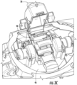
- body 14 includes chamber 46 (see FIG. 3A ) accessible at least via opening 50. Additionally illustrated in FIG. 1 is cover 54. Cover 54 preferably abuts opening 50 during operation of cleaner 10, closing access to chamber 46 from above. By contrast, FIG. 1 shows cover 54 having been moved relative to opening 50 so as to expose chamber 46 from above. In this position, cover 54 allows access to chamber 46 and to fluid-powered motor 58 positioned at least partially therein.
- Cover 54 may attach to body 14 in any appropriate manner.
- FIG. 1 illustrates cover 54 connecting to body 14 using a pin or hinges so that the cover 54 may pivot to and from the open position shown in FIG. 1 .
- a latch, snaps, or any other suitable fasteners may be used to retain the cover 54 in that position during operation of APC 10.
- a user may simply push a button to unfasten cover 54 from body 14 and thus allow cover 54 to pivot under manual or mechanical force.
- Persons skilled in the art will recognize that other methods of causing movement of cover 54 manually, without using tools, may be employed instead.
- At least some versions of cleaner 10 will connect, via at least one hose, to an inlet of a pump of a water-circulation system of a swimming pool.
- These versions are known as “suction-side” cleaners because of their connection to a pump inlet.
- the pump evacuates cleaner 10, drawing debris-laden water from the pool through an inlet of body 14 into the hose for eventual travel to a filter to separate and remove debris from the water.
- versions of cleaner 10 may be "pressure-side” cleaners, connecting directly or indirectly to an outlet of such a pump. In these APCs, pressurized water exiting the pump is used, employing the Venturi principle, to create a low-pressure area configured to draw debris-laden water into the inlet of body 14.
- motor 58 may constitute a turbine resembling that of the Rief patent.
- motor 58 may include housing 62 defining interior vacuum chamber 66 and having interior chamber wall 70, inlet port 74, and outlet port 78.
- Rotor 82 may be mounted within housing 62 on shaft 86 and configured to rotate about an axis coincident with the shaft 86.
- Inlet port 74 preferably is near the inlet of body 14 so that water entering that inlet may pass generally unobstructed to the inlet port 74.
- outlet port 78 preferably is, or is near, an outlet of cleaner 10 to which a hose may be connected directly or indirectly.
- spokes 90 Extending radially from an outer circumference of rotor 82 are spokes 90. Seven such spokes 90 are illustrated as so extending in FIG. 2 , with spokes 90 being spaced uniformly along the outer circumference. More or fewer spokes 90 may be employed, however, and their spacing need not necessarily be uniform.
- Pivotally attached to each spoke 90 is a vane 94, with vanes 94 beneficially pivoting about axes parallel to that about which rotor 82 rotates.
- Collectively, at least rotor 82, shaft 86, spokes 90, and vanes 94 may be considered to constitute core 98 of motor 58.
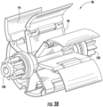
- gears 100 (see FIG. 3B ) additionally may be part of core 98. Gears 100 may, directly or indirectly, help drive the drive wheels 34.
- Housing 62 may be formed of more than one part.
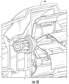
- FIG. 1 illustrates upper portion 102 of an exemplary housing 62 being attached to, or otherwise configured to move with, cover 54, while lower portion 106 (see FIG. 3F ) remains positioned within chamber 46 of body 14.
- cover 54 exposes core 98. This result is particularly useful when debris has impeded or obstructed operation of motor 58, as exposing core 98 may facilitate removal of that debris.
- core 98 may be configured within chamber 46 so that it is manually removable as a unit for cleaning, maintenance, repair, replacement, troubleshooting, or otherwise. Hence, merely by opening cover 54, core 98 is both exposed and available for removal from cleaner 10. Especially valuable is that no tool is required for any of these actions--manual manipulation of the components is sufficient.
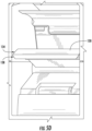
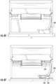
- FIGS. 3A-F illustrate and describe additional features of motor 58 and its interaction with, e.g., body 14.
- FIGS. 2 and 4A-C depict seal 110 which may be present within interior vacuum chamber 66 of motor 58.
- seal 110 helps bias water flow from inlet port 74 toward the right side of vacuum chamber 66 (as shown in FIG. 2 ) and promotes efficiency of engine operation. Generally, therefore, debris-laden water flows, and rotor 82 rotates, generally counterclockwise in FIG. 2 .
- seal 110 is flexible in nature. In particular, seal 110 may flex downward in FIG. 2 if necessary to allow passage of debris. Thus, seal 110 aids motor 58 in avoiding seizures by allowing debris to re-circulate within vacuum chamber 66.
- FIG. 4A shows a vane 94 in a normal sealed position against seal 110.
- Water pressure across the vane 94 helps retain this sealed relationship
- housing 62 may include rigid retention features 114 (see FIG. 4B ) preventing seal 110 from extending upward in FIG. 2 beyond a particular point.
- seal 110 may flex downward to accommodate extension of vane 94 (see FIG. 4B ) as well as to allow passage of debris (see FIG. 4C ). After debris passes, seal 110 may return to its normal position, as shown in FIG. 4A .
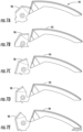
- FIGS. 5A-E depict structural features of a vane 94.
- Vane 94 may include a proximal portion 116 into which an elongated hole 118 is formed so as to receive a connector such as pin 222 (see FIG. 6A ). In this manner, vane 94 may connect to a corresponding spoke 90.
- Vane 94 also may include a distal portion 126 having an edge 130 as well as side edges 131 and 132. By tapering edges 131 and 132, the likelihood that debris will be trapped between a vane 94 and interior chamber wall 70 may be reduced without increasing leakage between the vane 94 and the wall 70.
- edge 130 may comprise leading portion 134 and lagging portion 138.
- leading portion 134 is configured so as to be perpendicular to the direction of motion of its vane 94, while lagging portion 138 has an angled surface.
- the perpendicular nature of leading portion 134 facilitates its moving debris while not channeling the debris toward any gap between components.
- the angled surface of lagging portion 138 by contrast, aids debris located between components to move out of any such gap.
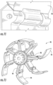
- FIGS. 6A-F illustrate pin 222.
- pin 222 may comprise a generally-straight first section 226 and a generally-curved second section 230.
- First section 226 is sized and shaped so as to be received by hole 118 of a vane 94 and forms an axis about which vane 94 can pivot.
- Second section 230 bears against surface protrusion 234 of rotor 82 (see, e.g., FIGS. 6C and 6F ), being retained in that position by rise 236 of rotor 82.
- first section 226 into hole 118, deform second section 230 so that it may pass over rise 236, and then allow second section 230 to relax so that it bears against surface protrusion 234.
- pin 222 may function as a pivot axis for a corresponding vane 94 while restricting any translation of the vane 94.
- the attachment process is reversible if necessary at least in part by re-deforming pin 222 and passing it back over rise 236.
- FIGS. 7A-J conceptually detail additional features of vanes 94.
- an APC includes gaps (around hinges between components, for example)
- debris may settle in or be forced into the gaps and potentially impede proper exercise of hinges or other moveable components.
- gaps sizes have been fixed prior to manufacturing production components: if made too large, more debris may settle in them; if made smaller, increased fabrication precision, leading to increased manufacturing costs, may occur.
- FIGS. 7A-J illustrate this concept, with FIG. 7A showing vane 94 in a sealed position with respect to spoke 90.
- FIGS. 7B-C illustrate vane 94 separating slightly from spoke 90, allowing release of accumulated debris.
- FIGS. 7D-E depict vane 94 returning to its sealed position relative to spoke 90. Similar functionality is illustrated in FIGS. 7F-I .
- FIG. 7J finally, illustrates core 98 with vanes 94 in various positions.
- FIG. 8 illustrates another exemplary APC 1000 incorporating aspects of the inventions.
- Cleaner 1000 may be similar to APC 10 shown in the previous figures, although such similarity is not necessary.
- Cleaner 1000 may include at least body 1014 and motive assembly 1018, with motive assembly 1018 comprising (closed-loop) track 1022 having external and internal surfaces 1026 and 1030, respectively.
- Motive assembly 1018 also may include pulley or drive wheel 1034 and undriven wheels 1038 and 1042.
- Drive wheel 1034 may include an oversized outer flange 1036 that helps retain track 1022 in position and prevent it from slipping laterally off the motive assembly 1018. More specifically, outer flange 1036 may be configured so it extends beyond external surface 1026 of track 1022 to serve as a stop against which track 1022 can abut, restricting lateral movement of track 1022. A motive assembly 1018 typically will be present at each of the left and right sides of cleaner 1000.
- track 1022 includes tread 1023 on external surface 1026 and teeth 1028 on internal surface 1030.
- the pattern of tread 1023 is such that tread 1023 is in-line with each tooth 1028. In this way, an axis 1037 of each tooth 1028 intersects at least a portion of tread 1023.
- This tooth 1028 to tread 1023 alignment leaves thin sections 1024 (corresponding to gaps between the teeth 1028 and gaps between the tread 1023), allowing track 1022 to remain flexible.
- track 1022 includes bridges 1032 that link the tread 1023. These bridges 1032 help prevent track 1022 from stretching.
- the vertical position of each bridge 1032 alternates between each tread 1023, such that adjacent bridges 1032 are vertically offset from one another. Offsetting bridges 1032 further helps track 1022 remain flexible.
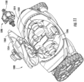
- body 1014 includes chamber 1046 accessible at least via opening 1050.
- cover 1054 preferably abuts opening 1050 during operation of cleaner 1000, closing access to chamber 1046 from above.
- FIG. 10 shows cover 1054 having been moved relative to opening 1050 into an open position so as to expose chamber 1046 from above. In this position, cover 1054 allows access to chamber 1046 and to fluid-powered motor 1058 positioned at least partially therein.
- Cleaner 1000 also includes a handle 1060, which can help facilitate carrying and manually moving cleaner 1000. Cleaner 1000 further includes scrub brushes 1044 for scrubbing the bottom of the swimming pool or other liquid-containing body. Any number of scrub brushes 1044 may be included and they make take any suitable form.
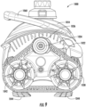
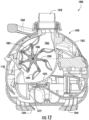
- cleaner 1000 may be configured as a suction-side cleaner or a pressure-side cleaner. In either case, water drawn into body 1014 additionally may operate fluid-powered motor 1058. As shown in FIG. 12 , motor 1058 may include housing 1062 defining interior vacuum chamber 1066 and having interior chamber wall 1070, inlet port 1074, and outlet port 1078. Rotor 1082 may be mounted within housing 1062 on shaft 1086 and configured to rotate about an axis coincident with the shaft 1086. Inlet port 1074 preferably is near the inlet of body 1014 so that water entering that inlet may pass generally unobstructed to the inlet port 1074. Similarly, outlet port 1078 preferably is, or is near, an outlet of cleaner 1000 to which a hose may be connected directly or indirectly.
- spokes 1090 Extending radially from an outer circumference of rotor 1082 are spokes 1090. Seven such spokes 1090 are illustrated as so extending in FIG. 12 , with spokes 1090 being spaced uniformly along the outer circumference. More or fewer spokes 1090 may be employed, however, and their spacing need not necessarily be uniform.
- Pivotally attached to each spoke 90 is a vane 1094, with vanes 1094 pivoting about axes parallel to that about which rotor 1082 rotates.
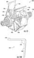
- core 1098 see FIGS. 11 and 13
- gears 1100 additionally may be part of core 1098. Gears 1100 may, directly or indirectly, help drive the drive wheels 1034.
- housing 1062 may be formed of more than one part if desired, although it need not be.
- core 1098 may be configured within chamber 1046 so that it is manually removable as a unit, as shown in FIG. 11 , for cleaning, maintenance, repair, replacement, troubleshooting, or otherwise. Hence, merely by opening cover 1054, core 1098 can be removed without obstruction from cleaner 1000 without requiring use of a tool, as shown in FIG. 11 .
- vanes 1094 of core 1098 may include a domed portion 1102 so a face of vane 1094 is convex.
- domed portion 1102 extends from a distal end to a proximal end of each vane 1094 to substantially cover face of vane 1094.
- debris that does not exit through outlet port 1078 may nest in cavity 1104 (see FIG. 12 ) created between housing 1062 and domed portion 1102 of vane 1094. This cavity 1104 allows the debris to circulate through the motor 1058 again without causing the motor 1058 to stall.
- cleaner 1000 may not have a seal such as seal 110 described with respect to cleaner 10.
- FIG. 14A illustrates pin 1222, which may comprise generally-straight first section 1226 and generally-straight second section 1230 separated by angle 1232.
- First section 1226 is sized and shaped so as to be received by a hole (such as hole 118 of vane 94) within vane 1094 and form an axis about which vane 1094 can pivot.
- Pin 1222 is trapped from lateral movement, as shown in the cross-sectional view of core 1098 in FIG. 14B , by the mating parts around it. No adhesive hence need be used to retain pin 1222 in appropriate position.
- no other component of cleaner 1000 need be deformed to allow placement of the pin 1222. Accordingly, in use pin 1222 may function as a pivot axis for a corresponding vane 1094 while restricting any translation of the vane 1094.
- references to “pools” and “swimming pools” herein may also refer to spas or other water containing vessels used for recreation or therapy and for which cleaning is needed or desired.
- Embodiment 1 A fluid-powered motor for an automatic swimming pool cleaner, the fluid-powered motor comprising:
- Embodiment 2 The fluid-powered motor as recited in embodiment 1, further comprising a seal, wherein the seal is (i) configured to move from a sealed position in a first direction to create space for passage of debris between the seal and the vane and (ii) prevented from moving from the sealed position in a second direction opposite the first direction.
- Embodiment 3 The fluid-powered motor as recited in embodiment 1, wherein the vane comprises at least one side portion with a tapered edge.
- Embodiment 4 The fluid-powered motor as recited in embodiment 1, wherein a proximal portion of the vane is connected to the at least one spoke and wherein the vane comprises a distal portion, the distal portion comprising:
- Embodiment 5 The fluid-powered motor as recited in embodiment 1, further comprising a pin connecting the vane to the at least one spoke, wherein the vane is rotatable about an axis of the pin.
- Embodiment 6 The fluid-powered motor as recited in embodiment 5, wherein the pin comprises a generally straight first section and a generally-curved second section.
- Embodiment 7 The fluid-powered motor as recited in embodiment 1, wherein the vane comprises a domed portion.
- Embodiment 8 The fluid-powered motor as recited in embodiment 7, wherein the domed portion extends across a face of the vane from a distal end to a proximal end of the face.
- Embodiment 9 The fluid-powered motor as recited in embodiment 1, wherein the vane is connected to the at least one spoke in a manner permitting a gap to form between the vane and the at least one spoke at first times during operation and for the vane and the at least one spoke to seal against each other at second times during operation.
- Embodiment 10 The fluid-powered motor as recited in embodiment 1, wherein the core is removable from a body of the automatic swimming pool cleaner as a module without using any tool.
- Embodiment 11 An automatic swimming pool cleaner comprising a motive assembly, the motive assembly comprising a drive wheel and a track, the track comprising an external surface and an internal surface, wherein:
- Embodiment 12 The automatic swimming pool cleaner as recited in embodiment 11, wherein gaps between the tread vertically align with gaps between the teeth to create flexible sections of the track.
- Embodiment 13 The automatic swimming pool cleaner as recited in embodiment 11, wherein the external surface of the track further comprises a plurality of bridges that connect the tread and extend along gaps between the tread, wherein adjacent bridges of the plurality of bridges are vertically offset from one another.
- Embodiment 14 The automatic swimming pool cleaner as recited in embodiment 11, wherein the drive wheel of the motive assembly comprises a flange that extends beyond the external surface of the track to serve as a stop that restricts lateral movement of the track beyond the flange.
- Embodiment 15 An automatic swimming pool cleaner comprising:
- Embodiment 16 The automatic swimming pool cleaner as recited in embodiment 15, further comprising a pin connecting each of the plurality of vanes to one of the plurality of spokes, wherein each of the plurality of vanes is rotatable about an axis of the pin.
- Embodiment 17 The automatic swimming pool cleaner as recited in embodiment 15, wherein at least one of the vanes of the plurality of vanes comprises a domed portion and, during operation of the fluid-powered motor, a cavity is formed between a housing of the fluid-powered motor and the domed portion.
- Embodiment 18 The automatic swimming pool cleaner as recited in embodiment 17, wherein the domed portion extends across a face of the at least one vane from a distal end to a proximal end of the face.
- Embodiment 19 The automatic swimming pool cleaner as recited in embodiment 15, further comprising a motive assembly comprising a drive wheel and a track, the track comprising an external surface and an internal surface, wherein:
- Embodiment 20 The automatic swimming pool cleaner as recited in embodiment 15, further comprising a motive assembly comprising a drive wheel and a track, the track comprising an external surface and an internal surface, wherein:
- Embodiment 21 The automatic swimming pool cleaner as recited in embodiment 15, further comprising a motive assembly comprising a drive wheel and a track, the track comprising an external surface and an internal surface, wherein: the external surface of the track comprises tread and a plurality of bridges that connect the tread, wherein adjacent bridges of the plurality of bridges are vertically offset from one another.
- Embodiment 22 The automatic swimming pool cleaner as recited in embodiment 15, further comprising a motive assembly comprising a drive wheel and a track, wherein the drive wheel comprises a flange that extends beyond an external surface of the track to serve as a stop that restricts lateral movement of the track beyond the flange.
- Embodiment 23 An automatic swimming pool cleaner comprising a motive assembly, wherein the motive assembly comprises a track and a drive wheel, the drive wheel comprising a flange that extends beyond an external surface of the track to serve as a stop that restricts lateral movement of the track beyond the flange.
Landscapes
- Engineering & Computer Science (AREA)
- Architecture (AREA)
- Civil Engineering (AREA)
- Structural Engineering (AREA)
- Mechanical Engineering (AREA)
- General Engineering & Computer Science (AREA)
- Nozzles For Electric Vacuum Cleaners (AREA)
- Devices For Medical Bathing And Washing (AREA)
- Connection Of Motors, Electrical Generators, Mechanical Devices, And The Like (AREA)
- Primary Cells (AREA)
- Motor Or Generator Cooling System (AREA)
- Cleaning In General (AREA)
Applications Claiming Priority (4)
| Application Number | Priority Date | Filing Date | Title |
|---|---|---|---|
| US201962837017P | 2019-04-22 | 2019-04-22 | |
| EP22170584.1A EP4056788B1 (de) | 2019-04-22 | 2020-04-14 | Automatische poolreiniger und komponenten dafür |
| PCT/US2020/028106 WO2020219301A1 (en) | 2019-04-22 | 2020-04-14 | Automatic swimming pool cleaners and components thereof |
| EP20722957.6A EP3935242B1 (de) | 2019-04-22 | 2020-04-14 | Flüssigkeitskraftbetriebener motor für einen automatischen schwimmbadreiniger |
Related Parent Applications (3)
| Application Number | Title | Priority Date | Filing Date |
|---|---|---|---|
| EP20722957.6A Division EP3935242B1 (de) | 2019-04-22 | 2020-04-14 | Flüssigkeitskraftbetriebener motor für einen automatischen schwimmbadreiniger |
| EP22170584.1A Division EP4056788B1 (de) | 2019-04-22 | 2020-04-14 | Automatische poolreiniger und komponenten dafür |
| EP22170584.1A Division-Into EP4056788B1 (de) | 2019-04-22 | 2020-04-14 | Automatische poolreiniger und komponenten dafür |
Publications (2)
| Publication Number | Publication Date |
|---|---|
| EP4459077A2 true EP4459077A2 (de) | 2024-11-06 |
| EP4459077A3 EP4459077A3 (de) | 2025-06-04 |
Family
ID=70476565
Family Applications (3)
| Application Number | Title | Priority Date | Filing Date |
|---|---|---|---|
| EP22170584.1A Active EP4056788B1 (de) | 2019-04-22 | 2020-04-14 | Automatische poolreiniger und komponenten dafür |
| EP24201102.1A Pending EP4459077A3 (de) | 2019-04-22 | 2020-04-14 | Automatische schwimmbeckenreiniger und komponenten davon |
| EP20722957.6A Active EP3935242B1 (de) | 2019-04-22 | 2020-04-14 | Flüssigkeitskraftbetriebener motor für einen automatischen schwimmbadreiniger |
Family Applications Before (1)
| Application Number | Title | Priority Date | Filing Date |
|---|---|---|---|
| EP22170584.1A Active EP4056788B1 (de) | 2019-04-22 | 2020-04-14 | Automatische poolreiniger und komponenten dafür |
Family Applications After (1)
| Application Number | Title | Priority Date | Filing Date |
|---|---|---|---|
| EP20722957.6A Active EP3935242B1 (de) | 2019-04-22 | 2020-04-14 | Flüssigkeitskraftbetriebener motor für einen automatischen schwimmbadreiniger |
Country Status (5)
| Country | Link |
|---|---|
| US (1) | US20200332546A1 (de) |
| EP (3) | EP4056788B1 (de) |
| AU (2) | AU2020263235B2 (de) |
| ES (2) | ES2997861T3 (de) |
| WO (1) | WO2020219301A1 (de) |
Families Citing this family (6)
| Publication number | Priority date | Publication date | Assignee | Title |
|---|---|---|---|---|
| USD950172S1 (en) * | 2020-02-02 | 2022-04-26 | Maytronics Ltd. | Swimming pool cleaner |
| FR3141960B1 (fr) * | 2022-11-16 | 2025-02-14 | Kokido Development Ltd | Balai aspirateur polyvalent pour le nettoyage de piscines |
| CN116641587B (zh) * | 2023-01-13 | 2025-10-28 | 深圳市元鼎智能创新有限公司 | 一种方便更换电池的泳池清洁机器人 |
| CN116065862B (zh) * | 2023-02-17 | 2025-10-17 | 远大健康科技(天津)有限公司 | 一种泳池清洁机 |
| US20250092623A1 (en) * | 2023-09-18 | 2025-03-20 | Taizhou Dibiao Technology Co., Ltd. | Roller brush of water surface cleaning robot |
| CN119641736B (zh) * | 2024-12-30 | 2025-06-24 | 德科隆(无锡)流体控制有限公司 | 一种液压回油联阀体 |
Citations (3)
| Publication number | Priority date | Publication date | Assignee | Title |
|---|---|---|---|---|
| US6292970B1 (en) | 1999-10-12 | 2001-09-25 | Poolvergnuegen | Turbine-driven automatic swimming pool cleaners |
| US20100119358A1 (en) | 2008-09-23 | 2010-05-13 | Van Der Meijden Hendrikus Johannes | Fluid-powered motors and pumps |
| US9611668B2 (en) | 2010-06-28 | 2017-04-04 | Zodiac Pool Systems, Inc. | Automatic pool cleaners and components thereof |
Family Cites Families (16)
| Publication number | Priority date | Publication date | Assignee | Title |
|---|---|---|---|---|
| US1516053A (en) * | 1922-12-09 | 1924-11-18 | John A Morgan | Pump |
| US5093950A (en) * | 1990-06-18 | 1992-03-10 | William Heier | Self propelled vacuum driven swimming pool cleaner |
| FR2665209A1 (fr) * | 1990-07-25 | 1992-01-31 | Chandler Michael | Dispositif de balai hydraulique pour bassin de piscine et analogue. |
| US6065289A (en) * | 1998-06-24 | 2000-05-23 | Quiet Revolution Motor Company, L.L.C. | Fluid displacement apparatus and method |
| US6131227A (en) * | 1998-10-30 | 2000-10-17 | Poolvergnuegen | Suction regulating skirt for automated swimming pool cleaner heads |
| FR2870280B1 (fr) * | 2004-05-12 | 2006-08-11 | Lagon Sa | Appareil motorise nettoyeur de piscine comportant des moyens de transmission du mouvement moteur en position de porte-a-faux |
| GB0518573D0 (en) * | 2005-09-12 | 2005-10-19 | Phoenix Product Dev Ltd | Self-aligning rotary piston machine |
| GB0711885D0 (en) * | 2007-06-19 | 2007-07-25 | Hozelock Ltd | Pond cleaning apparatus |
| US8402585B2 (en) * | 2009-10-19 | 2013-03-26 | Poolvergnuegen | Convertible pressure/suction swimming pool cleaner |
| US9593502B2 (en) * | 2009-10-19 | 2017-03-14 | Hayward Industries, Inc. | Swimming pool cleaner |
| EP3266959B1 (de) * | 2012-09-26 | 2019-07-31 | Hayward Industries, Inc. | Schwimmbeckenreiniger |
| US9822779B2 (en) * | 2013-02-05 | 2017-11-21 | Hanon Systems | Vane rotary compressor |
| US20140345562A1 (en) * | 2013-05-23 | 2014-11-27 | Abraham Hugo Horstin | Single-stage and three-stage internal combusion rotary engines |
| EP3187665B1 (de) * | 2013-08-30 | 2021-04-14 | Hayward Industries, Inc. | Schwimmbeckenreiniger |
| CN103967526A (zh) * | 2014-05-24 | 2014-08-06 | 周觉明 | 具有转轮连杆活塞机构的流体动力机械 |
| US10569819B2 (en) * | 2016-07-08 | 2020-02-25 | Polaris Industries Inc. | All-terrain vehicle |
-
2020
- 2020-04-14 EP EP22170584.1A patent/EP4056788B1/de active Active
- 2020-04-14 US US16/848,350 patent/US20200332546A1/en active Pending
- 2020-04-14 ES ES22170584T patent/ES2997861T3/es active Active
- 2020-04-14 EP EP24201102.1A patent/EP4459077A3/de active Pending
- 2020-04-14 EP EP20722957.6A patent/EP3935242B1/de active Active
- 2020-04-14 ES ES20722957T patent/ES2953942T3/es active Active
- 2020-04-14 AU AU2020263235A patent/AU2020263235B2/en active Active
- 2020-04-14 WO PCT/US2020/028106 patent/WO2020219301A1/en not_active Ceased
-
2024
- 2024-06-04 AU AU2024203751A patent/AU2024203751B2/en active Active
Patent Citations (3)
| Publication number | Priority date | Publication date | Assignee | Title |
|---|---|---|---|---|
| US6292970B1 (en) | 1999-10-12 | 2001-09-25 | Poolvergnuegen | Turbine-driven automatic swimming pool cleaners |
| US20100119358A1 (en) | 2008-09-23 | 2010-05-13 | Van Der Meijden Hendrikus Johannes | Fluid-powered motors and pumps |
| US9611668B2 (en) | 2010-06-28 | 2017-04-04 | Zodiac Pool Systems, Inc. | Automatic pool cleaners and components thereof |
Also Published As
| Publication number | Publication date |
|---|---|
| AU2020263235A1 (en) | 2021-11-25 |
| US20200332546A1 (en) | 2020-10-22 |
| EP4056788B1 (de) | 2024-10-30 |
| EP3935242B1 (de) | 2023-07-26 |
| EP3935242A1 (de) | 2022-01-12 |
| ES2997861T3 (en) | 2025-02-18 |
| WO2020219301A1 (en) | 2020-10-29 |
| AU2024203751A1 (en) | 2024-06-20 |
| AU2024203751B2 (en) | 2025-12-18 |
| EP4459077A3 (de) | 2025-06-04 |
| AU2020263235B2 (en) | 2024-05-02 |
| ES2953942T3 (es) | 2023-11-17 |
| EP4056788A2 (de) | 2022-09-14 |
| EP4056788A3 (de) | 2022-12-14 |
Similar Documents
| Publication | Publication Date | Title |
|---|---|---|
| EP3935242B1 (de) | Flüssigkeitskraftbetriebener motor für einen automatischen schwimmbadreiniger | |
| EP2585654B1 (de) | Automatische poolreiniger und bestandteile | |
| US9217260B2 (en) | Turbine-driven swimming pool cleaning apparatus and method | |
| AU2021224532B2 (en) | Automatic pool cleaner | |
| US9021645B2 (en) | Pool cleaning robot | |
| WO2014151086A2 (en) | Swimming pool pressure cleaner including automatic timing mechanism | |
| EP2340356B1 (de) | Fluidgetriebene motoren und pumpen | |
| CA2905970C (en) | Double paddle mechanism for pool cleaner | |
| CN224058286U (zh) | 用于水池自动清洁装置的尘盒 | |
| CN119237350A (zh) | 一种光伏板清洁机器人 | |
| CA2904677A1 (en) | Swimming pool pressure cleaner including automatic timing mechanism |
Legal Events
| Date | Code | Title | Description |
|---|---|---|---|
| PUAI | Public reference made under article 153(3) epc to a published international application that has entered the european phase |
Free format text: ORIGINAL CODE: 0009012 |
|
| STAA | Information on the status of an ep patent application or granted ep patent |
Free format text: STATUS: REQUEST FOR EXAMINATION WAS MADE |
|
| 17P | Request for examination filed |
Effective date: 20240918 |
|
| AC | Divisional application: reference to earlier application |
Ref document number: 3935242 Country of ref document: EP Kind code of ref document: P Ref document number: 4056788 Country of ref document: EP Kind code of ref document: P |
|
| AK | Designated contracting states |
Kind code of ref document: A2 Designated state(s): AL AT BE BG CH CY CZ DE DK EE ES FI FR GB GR HR HU IE IS IT LI LT LU LV MC MK MT NL NO PL PT RO RS SE SI SK SM TR |
|
| RIC1 | Information provided on ipc code assigned before grant |
Ipc: E04H 4/16 20060101AFI20250206BHEP |
|
| PUAL | Search report despatched |
Free format text: ORIGINAL CODE: 0009013 |
|
| AK | Designated contracting states |
Kind code of ref document: A3 Designated state(s): AL AT BE BG CH CY CZ DE DK EE ES FI FR GB GR HR HU IE IS IT LI LT LU LV MC MK MT NL NO PL PT RO RS SE SI SK SM TR |
|
| RIC1 | Information provided on ipc code assigned before grant |
Ipc: E04H 4/16 20060101AFI20250430BHEP |