EP4459083A1 - Contre-unité de verrouillage et dispositif de verrouillage à maintien de la durée mécanique - Google Patents
Contre-unité de verrouillage et dispositif de verrouillage à maintien de la durée mécanique Download PDFInfo
- Publication number
- EP4459083A1 EP4459083A1 EP23171831.3A EP23171831A EP4459083A1 EP 4459083 A1 EP4459083 A1 EP 4459083A1 EP 23171831 A EP23171831 A EP 23171831A EP 4459083 A1 EP4459083 A1 EP 4459083A1
- Authority
- EP
- European Patent Office
- Prior art keywords
- latch
- lock
- counter unit
- locking
- lock counter
- Prior art date
- Legal status (The legal status is an assumption and is not a legal conclusion. Google has not performed a legal analysis and makes no representation as to the accuracy of the status listed.)
- Pending
Links
Images




Classifications
-
- E—FIXED CONSTRUCTIONS
- E05—LOCKS; KEYS; WINDOW OR DOOR FITTINGS; SAFES
- E05B—LOCKS; ACCESSORIES THEREFOR; HANDCUFFS
- E05B17/00—Accessories in connection with locks
- E05B17/005—Preventing accidental lock-out, e.g. by obstruction in the striker
-
- E—FIXED CONSTRUCTIONS
- E05—LOCKS; KEYS; WINDOW OR DOOR FITTINGS; SAFES
- E05B—LOCKS; ACCESSORIES THEREFOR; HANDCUFFS
- E05B15/00—Other details of locks; Parts for engagement by bolts of fastening devices
- E05B15/02—Striking-plates; Keepers; Bolt staples; Escutcheons
- E05B15/0205—Striking-plates, keepers, staples
- E05B15/029—Closures, e.g. preventing dirt or paint from entering into the striker
-
- E—FIXED CONSTRUCTIONS
- E05—LOCKS; KEYS; WINDOW OR DOOR FITTINGS; SAFES
- E05C—BOLTS OR FASTENING DEVICES FOR WINGS, SPECIALLY FOR DOORS OR WINDOWS
- E05C7/00—Fastening devices specially adapted for two wings
- E05C7/04—Fastening devices specially adapted for two wings for wings which abut when closed
-
- E—FIXED CONSTRUCTIONS
- E05—LOCKS; KEYS; WINDOW OR DOOR FITTINGS; SAFES
- E05B—LOCKS; ACCESSORIES THEREFOR; HANDCUFFS
- E05B47/00—Operating or controlling locks or other fastening devices by electric or magnetic means
- E05B47/0001—Operating or controlling locks or other fastening devices by electric or magnetic means with electric actuators; Constructional features thereof
- E05B2047/0014—Constructional features of actuators or power transmissions therefor
- E05B2047/0018—Details of actuator transmissions
- E05B2047/0024—Cams
-
- E—FIXED CONSTRUCTIONS
- E05—LOCKS; KEYS; WINDOW OR DOOR FITTINGS; SAFES
- E05B—LOCKS; ACCESSORIES THEREFOR; HANDCUFFS
- E05B47/00—Operating or controlling locks or other fastening devices by electric or magnetic means
- E05B47/0001—Operating or controlling locks or other fastening devices by electric or magnetic means with electric actuators; Constructional features thereof
- E05B47/0012—Operating or controlling locks or other fastening devices by electric or magnetic means with electric actuators; Constructional features thereof with rotary electromotors
-
- E—FIXED CONSTRUCTIONS
- E05—LOCKS; KEYS; WINDOW OR DOOR FITTINGS; SAFES
- E05B—LOCKS; ACCESSORIES THEREFOR; HANDCUFFS
- E05B47/00—Operating or controlling locks or other fastening devices by electric or magnetic means
- E05B47/0046—Electric or magnetic means in the striker or on the frame; Operating or controlling the striker plate
-
- E—FIXED CONSTRUCTIONS
- E05—LOCKS; KEYS; WINDOW OR DOOR FITTINGS; SAFES
- E05B—LOCKS; ACCESSORIES THEREFOR; HANDCUFFS
- E05B63/00—Locks or fastenings with special structural characteristics
- E05B63/18—Locks or fastenings with special structural characteristics with arrangements independent of the locking mechanism for retaining the bolt or latch in the retracted position
- E05B63/20—Locks or fastenings with special structural characteristics with arrangements independent of the locking mechanism for retaining the bolt or latch in the retracted position released automatically when the wing is closed
Definitions
- the invention relates to a lock counter unit for use in a frame or in a passive leaf of a double-leaf door system, wherein the lock counter unit has a latch opening into which a latch of a lock can be brought into engagement.
- the lock counter unit is designed in particular as a strike plate or counter box unit.
- Such lock counter units for use in a frame or the like and a lock for use in a door leaf together form a locking device which can in particular be self-locking.
- the lock has a latch that can be retracted into the lock case by turning a follower of the lock, such as a door handle or a rotary knob.
- the lock can also have a bolt that can be pushed out of the lock case and retracted into the lock case, for example with a key in connection with a locking cylinder of the lock.
- the lock can also have an auxiliary latch that is designed to automatically protrude from the lock case and be pushed back into the lock case if the lock is to have a self-locking function.
- Lock counter units for use in a frame or in a passive leaf, in particular for self-locking locking devices, have at least one latch opening for a lock latch.
- the EP 2 037 063 B1 discloses a self-locking locking device with a lock counter unit, wherein a latch lock is provided inside the lock, by means of which the latch can be locked in the closed state of the door, wherein the latch lock is activated by a combined opening and locking function by pushing the bolt back out of the Lock counter unit can be released into the "unlocked position".
- a combined opening and locking function can be implemented, whereby an opening function is understood to mean a remote-controlled opening or unlocking of the locking system, for example via an electrical connection of the locking device to an external switching device. If this is activated, a key operation is no longer necessary to open the locking device, and in this way both unlocking and locking with the self-locking lock are possible.
- Such systems are used, for example, in remote-opening locking systems using electrical door handles, although the door closes and locks again after opening. The disadvantage of this is that electrical unlocking always has to take place.
- the object of the invention is to provide a simple design of a lock counter unit with a hold-open function for the locking device, so that the locking device does not close at least temporarily when the door closes and the lock overlaps with the lock counter unit. This should enable the door to be opened from both sides of the door without a key and/or from one side of the door that does not have a door handle without a key.
- an electrically activated door opener should be replaced or supplemented by a simple mechanism that can be operated on the lock counter unit.
- a simple mechanism should be able to be operated manually so that the opening-preventing function of the locking device is temporarily deactivated.
- the invention includes the technical teaching that the lock counter unit has a locking element which can be moved, in particular manually, at least partially into or over the latch opening, so that the latch can at least not protrude completely into the latch opening when a lock is brought into overlap with the lock counter unit.
- the core idea of the invention is a simple, in particular manually operable element that can be moved back and forth between at least two positions.
- the locking element can be operated and temporarily enable the lock device to be kept permanently open, in particular mechanically.
- the latch cannot protrude into the latch opening if the blocking element covers the latch opening at least to such an extent that the latch only comes to rest against the blocking element.
- the locking element is arranged in particular in front of an edge of the latch opening or flush with an edge of the latch opening. "In front of” is to be understood as a top view of the door frame with a built-in lock counter unit. If the locking element is arranged "in front of” the edge, the locking element is therefore located between the edge of the latch opening and a gap in the door.
- the locking element is arranged behind one edge of the latch opening. "Behind” is to be understood as a top view of the door frame with a built-in lock counter unit. This means that The edge of the latch opening is between the locking element and a gap in the door. The slight engagement of the latch in the latch opening makes it possible to keep the door leaf mechanically closed to a small extent.
- the latch can be pushed back into the lock when pressure is applied to the door leaf.
- the latch can be designed to be pivotable, as a roof latch, as a crank latch or as a roller latch.
- the latch can be designed as a cross latch. This is particularly important if the latch engages slightly in the latch opening when it is in contact with the locking element in order to ensure the hold-open function.
- the latch being placed against the locking element prevents the latch from becoming locked in the lock, so that the latch can be pushed back even if the lock is aligned with the lock counter-unit.
- the latch can be placed against the locking element to prevent the bolt from extending, particularly in the case of a self-locking lock.
- the latch can be placed against the locking element to prevent the bolt from locking in the lock.
- the blocking element can be moved back and forth, in particular manually, between a blocking position and a release position.
- the blocking position the blocking element prevents the trap from being fully retracted into the trap opening. Instead, the trap comes into contact with the blocking element. This achieves the hold-open function.
- the release position however, the blocking element allows the trap to be fully retracted into the trap opening. This cancels the hold-open function and the locking function of the locking device is restored.
- the lock counter unit can comprise a latch opening, wherein a latch of the lock can be engaged in the latch opening.
- the lock counter unit can be used on the frame of a single-leaf door.
- the lock counter unit can correspond to a strike plate. If the lock counter unit is designed as a strike plate, a latch handle and/or a bolt handle are missing in order to push a latch of the lock or a bolt of the lock back from the lock counter unit towards the lock via the lock counter unit.
- the lock counter unit can be designed as a counter box unit for use on a frame of a single-leaf door.
- the counter box unit can comprise a box body.
- a latch handle and/or a bolt handle can be arranged in the box body. By moving the latch handle, a latch of a lock can be forced out of the latch opening. By moving the bolt handle, a bolt of the lock can be forced out of the bolt opening.
- the lock counter unit can be used on a double-leaf door.
- the lock counter unit can be designed as a counter box unit with a box body.
- the counter box unit can comprise a nut for mechanically actuating the latch handle and/or bolt handle.
- the counter box unit for a double-leaf door can comprise at least one rod connection for connection to a bolt rod. The rod connection can be actuated via the nut.
- the lock counter unit comprises a fastening element for fastening the lock counter unit to the frame or the inactive leaf.
- the fastening element comprises, for example, screw holes for fastening the lock counter unit to the frame or the inactive leaf.
- the fastening element is designed as a faceplate of the strike box unit in the case of a strike box unit.
- the fastening element is designed as a strike plate base body.
- the locking element has a flat planar body which is arranged to be movable back and forth in the longitudinal extension along the fastening element of the lock counter unit between the release position and the locking position.
- the locking element is thus preferably designed as a flat planar body which can be moved back and forth between the release position and the locking position, in particular in the longitudinal extension along the fastening element, for example the strike plate base body or the faceplate of the lock counter unit.
- the locking element can be arranged to be movably guided on the outside or inside of the fastening element and can be moved back and forth between a release position and a locking position.
- the lock counter unit has in particular a holding element which is arranged in sections plane-parallel to the fastening element of the lock counter unit, wherein the locking element, in particular the planar body, is arranged in an arrangement between the fastening element and the holding element.
- corresponding millings or recesses can be provided in the fastening element or in the holding element in order to compensate for the thickness of the locking element, in particular of the planar body, and/or in particular to achieve a guiding effect in which the locking element, in particular of the planar body, is guided at the edge.
- the locking element is in particular designed as a surface element and/or is held in a form-fitting manner on the remaining lock counter-unit, so that the locking element can in particular only be moved back and forth in the extension plane of the holding element, for example upwards and downwards in relation to an installation position of the lock counter-unit.
- the lock counter unit has, for example, the box body with the holding element, which is arranged in sections plane-parallel to the faceplate of the lock counter unit, for example a side of the box body facing the faceplate.
- the planar body of the locking element can thus be arranged in an arrangement between the side of the box body that extends parallel to the faceplate and the faceplate.
- the holding element can be designed as a flat plate, e.g. made of metal or plastic, which is connected to the strike plate base body at least when installed.
- the holding element and the fastening element can, for example, comprise overlapping holes for fastening means, in particular screws.
- the strike plate base body is arranged between the holding element and the door gap.
- the locking element can have an operable projection for manual handling, which is arranged on the rest of the locking element, in particular on the planar body of the locking element.
- the projection is arranged on the rest of the locking element, in particular on the planar body, in particular so as to protrude vertically from the planar plane.
- an elongated recess is provided in the fastening element, into or through which the projection projects.
- a driver structure that can be operated manually can be applied to the surface of the locking element, in particular to the surface of the planar body that faces outwards from the fastening element, so that the locking element can be moved back and forth between the release position and the locking position, for example with a finger.
- a driver structure that can be operated manually can be applied to the surface of the locking element, in particular to the surface of the planar body that faces outwards from the fastening element, so that the locking element can be moved back and forth between the release position and the locking position, for example with a finger.
- recesses, holes, grooves or the like are made in the planar body of the locking element, so that the locking element can be moved back and forth between the release position and the locking position by manual operation even without a protruding projection.
- the lock counter unit can comprise an electrical switching element that is set up to detect the switching state of the locking element, namely the release position and the locking position.
- the switching state of the locking element can be monitored, for example, by means of a monitoring unit set up remotely from the lock counter unit, so that it can be detected whether the locking element remains in the locking position, for example, so that it can also be detected, for example by a building control center, whether the locking device remains permanently unlocked or not.
- the blocking element can have a switching projection that is arranged on the planar body of the blocking element so as to protrude therefrom and points in the direction of the electrical switching element in order to move a starting element of the electrical switching element when the blocking element is moved between the release position and the blocking position.
- the starting element of the electrical switching element forms, for example, a spring tongue that is pivotably attached to the electrical switching element.
- the switching projection can interact with the starting element so that the electrical switching element can recognize the position of the blocking element, i.e. in order to detect the release position or the blocking position. In the other position, selected from the release position or the blocking position, however, the switching projection preferably does not interact with the starting element.
- the switching projection may additionally or alternatively penetrate an elongated hole in the holding element in order to move a starting element of the electrical switching element when the locking element is moved between the release position and the locking position.
- the locking element comprises a holding means for holding the locking element in the locking position.
- the holding means is preferably designed as a latching holding means.
- the holding means can be designed as a cam, a thickening or, for example, a notch into which an engagement geometry, in particular a projection on a component of the lock counter unit, can latch in order to hold the locking element in the locking position.
- the locking element can be moved vertically during installation and should not leave the set position due to gravity.
- the locking element In the usually vertical installation position of the lock counter unit, the locking element is moved upwards against gravity and downwards with gravity between the release position and the locking position.
- the holding means in particular the latch between the cam, the thickening or the notch in the locking element, interacts with a counter geometry in the lock counter unit.
- the latching of the locking element in the release position and/or in the locking position can be set up in such a way that an operator receives haptic feedback as to whether the locking element is actually latched in the release position or in the locking position.
- the latching is provided at least for the upper position, which corresponds to the locking position, for example.
- the holding device can have a magnetic effect.
- the fastening element of the lock counter-unit has a recess in which the locking element is inserted, in particular with the flat planar body, so that the fastening element lies flat against the holding element, whereby the locking element is additionally guided.
- the locking element, in particular the planar body can for example have a thickness that is significantly less than the thickness of the fastening element, so that the locking element, in particular the planar body, can be inserted in the recess in the fastening element in such a way that the locking element, in particular the planar body, is between the fastening element and the holding element, e.g. the box body, are held securely.
- the locking element is made of a plastic material.
- a plastic material for example aluminum or a steel material
- an advantageous material pairing is created, particularly for the interaction between the cam, the thickening or the notch on the locking element in conjunction with the counter geometry of the lock counter unit, if the locking element is made of a plastic material.
- the locking behavior is positively influenced by this, since the plastic material is more flexible than a metallic material, so that the locking effect is also improved.
- the locking element can be accommodated under pre-tension between the strike plate and the retaining element of the box body.
- the locking element in the locking position has an incomplete, for example half, overlap with the latch opening.
- the locking element can therefore only have a partial overlap or an even smaller overlap with the latch opening in the locking position, which can be sufficient to prevent the latch from protruding completely into the latch opening.
- the half overlap can also be reduced even further, since the desired effect occurs even if the latch is only prevented by a small section by the locking element from engaging in the latch opening in the lock counter unit. Due to the incomplete overlap, the locking element can be short and thus designed to save space.
- the lock counter unit can be designed as a counter box unit with a box body.
- the box body comprises a receiving space for the trap, wherein a protective plate delimits the receiving space, in particular This protects the box body from contamination or attempts at manipulation.
- the counter box unit may comprise an electric actuator, in particular an electric motor.
- the actuator serves to electrically operate the latch handle and/or the bolt handle.
- the actuator is arranged in the box body.
- a slide unit guided linearly in the box body is operatively connected to the actuator.
- the slide unit can be displaced translationally by the actuator.
- the slide unit is operatively connected to the latch handle and/or the bolt handle.
- the actuator can be operatively connected to the latch handle and/or the bolt handle via the slide unit.
- the latch handle and/or the bolt handle can be designed as a pivoting lever.
- the latch handle and/or the bolt handle are preferably mounted in the box body about a rotationally fixed axis.
- the actuator and the slide unit are connected in particular via a gear to a rotatable gear wheel.
- An eccentric element is preferably arranged on the gear wheel.
- the slide unit has a slot in which the eccentric element is guided, so that when the gear wheel rotates, the eccentric element moves along the slot and moves the slide unit in a translational manner.
- the lock counter unit does not include a latch handle, but only a deadbolt handle. This is particularly possible if the latch is also unlocked by an operating mechanism in the lock when the deadbolt is pushed back. In this case, the latch can be pushed back into the lock when pressure is applied to the door leaf.
- the invention further relates to a locking device comprising a lock, in particular with a lock case, for use in a door leaf with a lock counter unit, as described above, wherein the lock has a latch which can be brought into engagement with the latch opening.
- the lock is designed to be self-locking. Self-locking occurs when the latch can fully protrude into the latch opening, i.e. when the locking element is in the release position. Self-locking does not occur, however, when the latch is prevented from fully protruding by the locking element, i.e. when the locking element is in the locking position.
- the lock comprises a bolt that is formed separately from the latch.
- the bolt springs out of the lock and engages in the lock counter unit, in particular in the bolt opening of the lock counter unit, by the bolt extending into the bolt opening of the lock counter unit, the locking device is locked.
- an operating mechanism in the lock case allows the bolt to spring out of the lock case when the self-locking locking device closes, i.e. the lock is brought into overlap with the lock counter unit.
- the bolt can be extended, for example, if the latch bolt is pushed forward into the latch opening of the lock counter unit when the locking element is in the release position. However, if the locking element is in the locking position and the latch bolt cannot be pushed forward completely into the latch opening, the lock can be designed so that the bolt does not extend.
- the lock may include an auxiliary latch to trigger or co-trigger the self-locking mechanism.
- an auxiliary latch to trigger or co-trigger the self-locking mechanism.
- the latch and/or the auxiliary latch are pressed into the lock case, for example when the locking device is closed and the latch and the auxiliary latch come into contact with the lock counter unit and are pressed in. This may in particular be an additional condition for the bolt to be able to extend. It may be provided that the auxiliary latch remains pressed in when the locking device is closed.
- the movement of the locking element into the locking position can, as long as the locking element remains in the locking position, prevent the bolt from engaging the lock counter unit again when the locking device closes again with the door.
- This is achieved by at least partially preventing the latch from engaging the latch opening in the lock counter unit if the locking element has been moved at least partially into or over the latch opening.
- the latch and, for example, the auxiliary latch can be pushed back into the lock case, but the latch does not shoot forward into the latch opening because it comes into contact with the locking element which blocks the latch opening. This means that the bolt does not shoot forward into the lock counter unit again either.
- the bolt Due to the internal mechanism of the lock between the latch and the movement of the bolt, the bolt is not activated to spring forward, as it only springs forward when the latch can engage the latch opening in the lock counter unit and in particular when the auxiliary latch comes into contact with the front of the strike plate. If the condition that the latch does not spring forward, but the auxiliary latch remains pushed back, is not met, the lock will not lock either, as the bolt remains in the retracted position within the lock.
- the internal mechanism of the lock is designed to prevent the latch from being pushed back when the latch has sprung forward. It should be provided that when the locking element is in the locked position, the latch can be pushed back into the lock. When the locking element is in the released position, however, the latch cannot be pushed back.
- the latch can comprise at least one pivotable latch head, wherein the latch head is pivotable when the latch is prevented from fully protruding by the locking element. When the latch fully protrudes, however, the pivoting of the latch head is blocked. This means that pivoting of the latch head is possible when the locking element is in the locked position. However, pivoting of the latch head is blocked when the locking element is in the released position. As a result, the hold-open function can be ensured by the locking position of the locking element. Even if the latch dips slightly into the latch opening when the locking element is in the locked position, pivoting the latch head can move the latch head at an angle relative to the lock counter unit, thus allowing the latch to be pushed back into the lock case.
- the lock preferably comprises a linearly movable, mechanical control element, in particular a slider.
- the control element assumes a first position when the latch is prevented from fully protruding by the locking element, i.e. in the locking position of the locking element.
- the control element assumes a second position when the latch has fully protruded, i.e. in the release position of the locking element.
- first position of the control element pivoting of the latch head and/or pushing back of the latch is possible.
- the bolt is held back in the lock.
- pivoting of the latch head and/or pushing back of the latch is blocked.
- the bolt is extended from the lock.
- the latch and the control element can be in operative connection when the latch is pushed back and the control element is in the first position, so that the latch prevents the control element from moving to the second position.
- the trap can, for example, engage in a bulge in the control element.
- control element in the first position, can position a blocking element in such a way that pivoting of the trap head is prevented and/or pushing the trap back is prevented. In the second position, however, the control element releases the blocking element so that the trap is not blocked.
- the control element can be connected to the bolt via a guide. By moving the control element from the first position to the second position, the bolt is moved out of the lock case via the guide.
- Pushing the bolt back causes the control element to move from the second to the first position via the guide. This unlocks the latch. This means that a latch lever is not required in the lock counter unit.
- Figure 1 shows the locking device 100 according to the invention with a self-locking lock 10, which can be inserted into a door leaf, for example, and with a lock counter unit 12 according to the invention, which can be inserted into a frame of a door device or into a passive leaf of a double-leaf door system, for example.
- the lock 10 is designed with a lock case 11 and has a latch 13, a follower 14 and a bolt 15, with a so-called auxiliary latch 16 also being installed.
- the further locking mechanism and the mechanical operative connection between the latch 13, the auxiliary latch 16, the bolt 15 and the follower 14 are only briefly described. described, as known from the document EP2673434 B1 , to which reference is made here.
- the latch 13 When the handle nut 14 is turned, for example with a door handle or rotary knob, the latch 13 can be released and the bolt 15 can be retracted into the lock case 11 of the lock 10, which is shown in the retracted position in the view.
- a mechanical control element designed here as a slide 31, is provided.
- the slide 31 When the handle nut 14 is turned, the slide 31 is moved from a second, lower position to a first, upper position.
- the bolt 15 In the first position of the slider 31 shown here, the bolt 15 is retracted. In the second position of the slider, the bolt 15 is extended from the lock case 11.
- the slider 31 is connected to the bolt 15 via a link 32, which determines the mutual positions.
- the latch 13 In the first position of the slider 31, the latch 13 can be pushed back into the lock case 11.
- the latch 13 is designed as a cross latch with pivotable latch wings. In the first position of the slider 31, the latch wings can be pivoted. This is made possible by the slider 31 or a blocking element that moves with the slider 31 being out of operative connection with the latch 13.
- the latch 13 In the second position of the slider 31, the latch 13 cannot be pushed back into the lock case 11 by the slider 31 itself or the blocking element that moves with it.
- the latch wings In addition, in the second position of the slider 31, the latch wings cannot be pivoted by a blockage of the slider 31 itself or the blocking element that moves with it.
- the slider 31 can move from the first, upper position to a second, lower position when the latch 13 and the auxiliary latch 16 are pressed in and then the latch 13 extends again. This is a movement that causes the bolt 15 to spring forward.
- the slider 31 or the blocking element moves in operative connection with the latch 13, so that the latch 13 is prevented from being pushed back and the latch wings from pivoting.
- the latch 13 is pressed out of the lock case 11 by a spring. Furthermore, a further spring is provided which pushes the slider 31 into the second position and thereby moves the bolt 15 out of the lock case 11. In the first position of the slider 31, the slider 31 is held against the action of the further spring by a mechanism in which the auxiliary latch 16 is involved, see also EP2673434 B1 , which describes this mechanism in detail.
- the auxiliary latch 16 may have a projection in engagement with the slide 31, which holds the slide 31 in the first position against the force of the additional spring. In this case, pressing in the auxiliary latch 16 when the latch 13 is extended leads to a movement of the slide 31 into the second position and to the bolt 15 springing out.
- a pushed-back latch 13 secures the slide 31 in the first position.
- the latch 13 comprises a roller 33 with which the latch 13 can move into a recess 34 of the slide 31 in the pushed-back position. This holds the slide 31 in the first position against the force of the additional spring.
- the auxiliary latch 16 must always be pushed back and the latch 13 extended.
- the lock counter unit 12 comprises a bolt opening 18.
- the lock counter unit 12 has the locking element 19 according to the invention, which can be moved back and forth between two positions in order to release the latch opening 17 in a release position or as shown in Figure 1 in a locked position to at least partially cover it.
- the latch 13 cannot spring forward into the latch opening 17 if the locking device lock 10 and lock counter unit 12 are brought into overlap, ie the door is closed.
- the latch 13 is also pushed back and is retracted with the roller 33 in the recess 34 of the slide 31, the slide 31 is held in the first position. This means that the bolt 15 is not triggered from snapping forward into the bolt opening 18.
- the locking mechanism ensures in a known manner that the bolt 15 springs forward into the latch opening 18 and locks the lock, since the latch 13 can also spring forward into the latch opening 17.
- FIGs 2 and 3 show a section of the lock counter unit 12 with a locking element 19 in different positions.
- the locking element 19 is according to Figure 2 retracted from the opening area of the latch opening 17 and is therefore in the release position I.
- the locking element 19 has been partially pushed forward over the latch opening 17 and covers it, resulting in the locking position II, and the self-locking lock cannot lock even if the lock 10 is covered by the lock counter unit 12 shown, since the locking element 19 prevents the latch from rushing forward into the latch opening 17.
- the lock counter unit 12 comprises a faceplate 21 as a fastening element and a box body 22. As in Figure 1 As shown, the faceplate 21 projects beyond the box body 22. Holes (not shown) in the part of the faceplate 21 projecting beyond the box body 22 serve to fasten the lock counter unit 12 to the frame by means of screws.
- the face plate 21 is attached to the box body 22 by Figures 2 and 3 holes shown, which are arranged above and below the trap opening.
- the locking element 19 is movably mounted on the faceplate 21 and has a manually operable projection 24 which extends through an elongated recess 25 in the strike plate 21 so that the locking element 19 can be manually moved back and forth between the release position I and the locking position II by an operator from the outside.
- the locking element 19 is locked in the upper locking position II so that it does not return to the lower release position I due to gravity.
- the locking element 19 has a notch 29 (see. Figures 7 and 8 ). At the edge of the latch opening 17 there is a corresponding locking projection (not shown) which can engage in the notch 29.
- the locking element 19 is made of plastic.
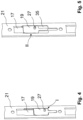
- FIGs 4 and 5 show in a perspective view the faceplate 21 of the lock counter unit from the back of the faceplate 21, whereby in Figure 4 the locking element 19 in the release position I and in Figure 5 shown arranged in the locking position II.
- the locking element 19 comprises a flat planar body 20.
- the face plate 21 comprises a recess 35 in which the locking element 19 is guided.
- the recess is designed such that the planar body 20 is completely received in the recess 35.
- Figure 6 shows an enlarged view of the lock 10 and the lock counter unit 12, which form the entire locking device 100, wherein the lock 10 has a lock case 11 with a front faceplate 30 and the lock counter unit 12 has the case body 22 with a section-wise holding element 23, wherein the holding element 23 is flat and arranged parallel and spaced apart from or adjacent to the faceplate 21 of the lock counter unit 12.
- the faceplate 21 of the lock counter unit 12 on the front of the case body 22 is opposite a faceplate 30 of the lock 10 when the locking device 100 is closed.
- the holding element 23 corresponds in this case to a section of a side of the box body 22 which faces the face plate 21.
- the locking element 19 according to the invention is received between the holding element 23 and the faceplate 21, and the manually operable projection 24 is shown extending through the elongated recess 25 so that an operator can use the projection 24 to move the position of the locking element 19 back and forth between the release position and the locking position when the locking device 100 is opened and the strike plate 21 is freely accessible.
- auxiliary latch 16 comes to rest against the faceplate 21, whereas the latch 13 cannot protrude into the latch opening 17 since this is partially closed by the locking element 19.
- the illustration also shows an electrical switching element 26 with a starting element 28, so that depending on the switching position of the locking element 19, the starting element 28 can be moved into a first and a second switching position, so that the electrical switching element 26 can detect whether the locking element 19 is in the release position or in the locking position.
- the movement of the starting element 28 is caused by a tactile interaction with the switching projection 27 of the locking element 19.
- Figure 7 shows the locking element 19 with the planar body 20, and on a planar side facing the outside of the lock counter unit 19, the planar body 20 has the manually operable projection 24, and on an opposite side, the switching projection 27 is shown in order to interact with the starting element of the electrical switching device, as in Figure 8 shown. It can be seen here that the starting element 28 of the electrical switching element 26 is moved with the planar body 20 depending on the position of the locking element 19, so that the switching projection 27 compresses or rebounds the starting element 28 towards or away from the switching element 26 depending on the direction of movement.
- the holding element 23 comprises an elongated hole through which the switching projection 27 protrudes.
- the lock counter unit 12 comprises the box body 22.
- a protective plate 37 separates a receiving space for the latch 13 behind the latch opening 17 from the rest of the box body 22.
- the lock counter unit 12 comprises an electric actuator, which is designed as an electric motor 38.
- a bolt handle 39 of the lock counter unit 12 can be pivoted by means of the electric motor 38. The bolt handle 39 moves the bolt 15 back into the lock case 11.
- the slider 31 By pushing back the bolt 15, the slider 31 is moved from the second position to the first position. This unlocks the latch 13.
- the latch wings can be pivoted so that the latch 13 can be pushed back into the lock case 11 when pressure is applied to the door leaf. This makes it possible to open the door.
- the movement caused by the actuator 38 means that the door can be opened when the actuator 38 is energized. This means that the door can be opened when the locking element 19 is in the release position. If the locking element 19 is in the locking position, it is not necessary to energize the actuator 38, since the door can already be opened when the latch 13 is in contact with the locking element 19.
- the actuator 38 is connected to the latch handle 39 via a linearly movable slide unit 42.
- the slide unit 42 can assume a first slide position and a second slide position. In the first, upper slide position, the latch handle 39 is retracted. In the second, lower slide position, the latch handle is pivoted forward. The latch handle 39 moves the latch 15 by moving the latch handle 39 from the retracted to the pivoted forward position. To do this, the slide unit 42 must be moved from the first slide position to the second slide position. In the Figure 1 the slide unit 42 is in the second Position and thus the bolt handle 39 in the forward-pivoted position in which the bolt handle has pushed the bolt 15 back into the lock case 11.
- the actuator 38 drives a gear wheel 40 with an eccentric element 41.
- the eccentric element 41 engages in a slot 44 of the slide unit 42.
- the gear wheel 40 rotates, the eccentric element 41 moves along the slot 44. This causes the slide unit 42 to move in a translational manner.
- the latch lever 39 is pivotally mounted about a fixed axis 36 in the box body 22.
- the slide unit 42 engages with a projection 43 in a recess of the latch lever 39 in order to pivot the latch lever 39.
- the lock counter unit 12 shown in the embodiment is intended for installation in a frame of a single-leaf door. As a result, the lock counter unit 12 is designed without a nut for mechanically moving the latch handle 39. Furthermore, no connection for a latch bar is provided in the lock counter unit 12.
- the lock counter unit 12 can be designed for a passive leaf of a double-leaf door.
- the slide unit can be additionally or Alternatively to the actuator 38, it can be mechanically operated via a nut.
- the lock counter unit 12 can comprise a connection for a locking bar.
- the lock counter unit can be designed as a strike plate without a box body.
- the holding element can be designed as a plate.
- a strike plate base body is provided, which can be designed identically to the faceplate 21.
- the strike plate base body can thus comprise a recess 35 for guiding the locking element 19.
- the strike plate base body can comprise an elongated recess 25 for guiding the projection 24.
- the strike plate base body can comprise holes in order to be fastened to the frame by means of screws.
- the strike plate base body can comprise fastening means, such as projections or further holes, with which the strike plate base body and the holding element are connected to one another.
- the holding element comprises corresponding fastening means for this purpose.
- the lock counter unit is designed as a strike plate, the switching element 27 is missing.
- the locking element 19 can thus be designed without a switching projection 27.
- the elongated hole in the holding element 23 may accordingly be missing.
Landscapes
- Engineering & Computer Science (AREA)
- Mechanical Engineering (AREA)
- Lock And Its Accessories (AREA)
Priority Applications (1)
| Application Number | Priority Date | Filing Date | Title |
|---|---|---|---|
| EP23171831.3A EP4459083A1 (fr) | 2023-05-05 | 2023-05-05 | Contre-unité de verrouillage et dispositif de verrouillage à maintien de la durée mécanique |
Applications Claiming Priority (1)
| Application Number | Priority Date | Filing Date | Title |
|---|---|---|---|
| EP23171831.3A EP4459083A1 (fr) | 2023-05-05 | 2023-05-05 | Contre-unité de verrouillage et dispositif de verrouillage à maintien de la durée mécanique |
Publications (1)
| Publication Number | Publication Date |
|---|---|
| EP4459083A1 true EP4459083A1 (fr) | 2024-11-06 |
Family
ID=86330253
Family Applications (1)
| Application Number | Title | Priority Date | Filing Date |
|---|---|---|---|
| EP23171831.3A Pending EP4459083A1 (fr) | 2023-05-05 | 2023-05-05 | Contre-unité de verrouillage et dispositif de verrouillage à maintien de la durée mécanique |
Country Status (1)
| Country | Link |
|---|---|
| EP (1) | EP4459083A1 (fr) |
Citations (11)
| Publication number | Priority date | Publication date | Assignee | Title |
|---|---|---|---|---|
| DE1428522A1 (de) * | 1964-12-01 | 1968-12-12 | Reinhard Hering | Automatische Schlossfallensperre |
| NL6812606A (fr) * | 1968-09-05 | 1970-03-09 | ||
| SE388451B (sv) * | 1975-02-07 | 1976-10-04 | Das Lasfabrik Ab | Slutbleck med kolvsperr |
| GB2228291A (en) * | 1989-02-09 | 1990-08-22 | Goodwin W J & Son Ltd | Striker plate |
| DE9412827U1 (de) * | 1994-08-09 | 1994-10-06 | Zittenzieher, Franz, 81671 München | Offenhaltevorrichtung |
| FR2771126A1 (fr) * | 1997-11-17 | 1999-05-21 | Fontaine Sa | Serrure a commande electrique |
| WO2007003920A2 (fr) * | 2005-07-01 | 2007-01-11 | D & K Products Ltd | Verrou de porte antiverrouillage et recepteur |
| DE102009056348A1 (de) * | 2009-11-25 | 2011-06-09 | Reinhard Beierlein | Universeller elektrischer Türöffner für selbstverriegelnde Fallenpanikschlösser u.a. |
| EP2037063B1 (fr) | 2006-03-10 | 2013-05-15 | ASSA ABLOY Sicherheitstechnik GmbH | Système de verrouillage d'une porte |
| EP2673434B1 (fr) | 2011-02-08 | 2016-07-06 | DORMA Deutschland GmbH | Serrure dotée d'un loquet et d'un loquet supplémentaire destiné à empêcher le déplacement d'un pêne |
| WO2021258133A1 (fr) * | 2020-06-22 | 2021-12-30 | Interface Innovation Pty Ltd | Désactivateur de verrou |
-
2023
- 2023-05-05 EP EP23171831.3A patent/EP4459083A1/fr active Pending
Patent Citations (11)
| Publication number | Priority date | Publication date | Assignee | Title |
|---|---|---|---|---|
| DE1428522A1 (de) * | 1964-12-01 | 1968-12-12 | Reinhard Hering | Automatische Schlossfallensperre |
| NL6812606A (fr) * | 1968-09-05 | 1970-03-09 | ||
| SE388451B (sv) * | 1975-02-07 | 1976-10-04 | Das Lasfabrik Ab | Slutbleck med kolvsperr |
| GB2228291A (en) * | 1989-02-09 | 1990-08-22 | Goodwin W J & Son Ltd | Striker plate |
| DE9412827U1 (de) * | 1994-08-09 | 1994-10-06 | Zittenzieher, Franz, 81671 München | Offenhaltevorrichtung |
| FR2771126A1 (fr) * | 1997-11-17 | 1999-05-21 | Fontaine Sa | Serrure a commande electrique |
| WO2007003920A2 (fr) * | 2005-07-01 | 2007-01-11 | D & K Products Ltd | Verrou de porte antiverrouillage et recepteur |
| EP2037063B1 (fr) | 2006-03-10 | 2013-05-15 | ASSA ABLOY Sicherheitstechnik GmbH | Système de verrouillage d'une porte |
| DE102009056348A1 (de) * | 2009-11-25 | 2011-06-09 | Reinhard Beierlein | Universeller elektrischer Türöffner für selbstverriegelnde Fallenpanikschlösser u.a. |
| EP2673434B1 (fr) | 2011-02-08 | 2016-07-06 | DORMA Deutschland GmbH | Serrure dotée d'un loquet et d'un loquet supplémentaire destiné à empêcher le déplacement d'un pêne |
| WO2021258133A1 (fr) * | 2020-06-22 | 2021-12-30 | Interface Innovation Pty Ltd | Désactivateur de verrou |
Similar Documents
| Publication | Publication Date | Title |
|---|---|---|
| EP2037063B1 (fr) | Système de verrouillage d'une porte | |
| WO2007104499A2 (fr) | Dispositif de verrouillage pour une porte | |
| EP2474692A2 (fr) | Dispositif de serrure de porte et procédé d'ouverture d'un dispositif de serrure de porte | |
| WO2012107167A1 (fr) | Système de serrure pour bloc-porte à deux vantaux à fonction anti-panique | |
| DE19514742A1 (de) | Rohrrahmenschloß | |
| EP0945572A2 (fr) | Ensemble de serrure de porte, de préférence crémone-serrure | |
| EP2673434B1 (fr) | Serrure dotée d'un loquet et d'un loquet supplémentaire destiné à empêcher le déplacement d'un pêne | |
| EP3051045B1 (fr) | Dispositif de commutation | |
| EP2706174B1 (fr) | Serrure pour une porte | |
| EP0858541B1 (fr) | Dispositif de verrouillage | |
| EP2820208B1 (fr) | Serrure | |
| DE202015105732U1 (de) | Verschlussmechnismus | |
| EP3543436B1 (fr) | Contre-serrure pour vantail passif | |
| EP3159466B1 (fr) | Dispositif de verrouillage comprenant deux corps de verrouillages mobiles | |
| WO2009118276A1 (fr) | Serrure anti-panique | |
| EP3249141B1 (fr) | Serrure comprenant un pêne et un pêne supplémentaire pour la sécurité d'écoulement | |
| EP0779403B1 (fr) | Serrure de sécurité | |
| DE10125915A1 (de) | Fehlbedienungssicheres Schiebeflügel- oder Schwenkflügelschloss | |
| EP1617018B1 (fr) | Serrure de porte électromécanique | |
| EP3208407B1 (fr) | Verrou dote d'un dispositif de securite | |
| EP3543437B1 (fr) | Dispositif formant serrure pourvu d'une serrure pour une porte à battants mobiles | |
| DE3414642C3 (de) | Blockschloß | |
| EP2738324B1 (fr) | Serrure dotée d'une unité de rotation débloquable | |
| DE10011610C1 (de) | Türöffner | |
| EP2716846B1 (fr) | Verrou de porte |
Legal Events
| Date | Code | Title | Description |
|---|---|---|---|
| PUAI | Public reference made under article 153(3) epc to a published international application that has entered the european phase |
Free format text: ORIGINAL CODE: 0009012 |
|
| STAA | Information on the status of an ep patent application or granted ep patent |
Free format text: STATUS: THE APPLICATION HAS BEEN PUBLISHED |
|
| AK | Designated contracting states |
Kind code of ref document: A1 Designated state(s): AL AT BE BG CH CY CZ DE DK EE ES FI FR GB GR HR HU IE IS IT LI LT LU LV MC ME MK MT NL NO PL PT RO RS SE SI SK SM TR |
|
| STAA | Information on the status of an ep patent application or granted ep patent |
Free format text: STATUS: REQUEST FOR EXAMINATION WAS MADE |
|
| 17P | Request for examination filed |
Effective date: 20250505 |