EP4459086A1 - Serrure encastrée pour portes - Google Patents
Serrure encastrée pour portes Download PDFInfo
- Publication number
- EP4459086A1 EP4459086A1 EP24164862.5A EP24164862A EP4459086A1 EP 4459086 A1 EP4459086 A1 EP 4459086A1 EP 24164862 A EP24164862 A EP 24164862A EP 4459086 A1 EP4459086 A1 EP 4459086A1
- Authority
- EP
- European Patent Office
- Prior art keywords
- nut
- actuating
- coupling
- latch
- faceplate
- Prior art date
- Legal status (The legal status is an assumption and is not a legal conclusion. Google has not performed a legal analysis and makes no representation as to the accuracy of the status listed.)
- Pending
Links
Images




Classifications
-
- E—FIXED CONSTRUCTIONS
- E05—LOCKS; KEYS; WINDOW OR DOOR FITTINGS; SAFES
- E05B—LOCKS; ACCESSORIES THEREFOR; HANDCUFFS
- E05B63/00—Locks or fastenings with special structural characteristics
- E05B63/08—Mortise locks
-
- E—FIXED CONSTRUCTIONS
- E05—LOCKS; KEYS; WINDOW OR DOOR FITTINGS; SAFES
- E05B—LOCKS; ACCESSORIES THEREFOR; HANDCUFFS
- E05B47/00—Operating or controlling locks or other fastening devices by electric or magnetic means
- E05B47/06—Controlling mechanically-operated bolts by electro-magnetically-operated detents
- E05B47/0676—Controlling mechanically-operated bolts by electro-magnetically-operated detents by disconnecting the handle
- E05B47/0684—Controlling mechanically-operated bolts by electro-magnetically-operated detents by disconnecting the handle radially
- E05B47/0692—Controlling mechanically-operated bolts by electro-magnetically-operated detents by disconnecting the handle radially with a rectilinearly moveable coupling element
-
- E—FIXED CONSTRUCTIONS
- E05—LOCKS; KEYS; WINDOW OR DOOR FITTINGS; SAFES
- E05B—LOCKS; ACCESSORIES THEREFOR; HANDCUFFS
- E05B55/00—Locks in which a sliding latch is used also as a locking bolt
- E05B55/06—Locks in which a sliding latch is used also as a locking bolt the handle being disconnected
-
- E—FIXED CONSTRUCTIONS
- E05—LOCKS; KEYS; WINDOW OR DOOR FITTINGS; SAFES
- E05B—LOCKS; ACCESSORIES THEREFOR; HANDCUFFS
- E05B63/00—Locks or fastenings with special structural characteristics
- E05B63/16—Locks or fastenings with special structural characteristics with the handles on opposite sides moving independently
-
- E—FIXED CONSTRUCTIONS
- E05—LOCKS; KEYS; WINDOW OR DOOR FITTINGS; SAFES
- E05B—LOCKS; ACCESSORIES THEREFOR; HANDCUFFS
- E05B47/00—Operating or controlling locks or other fastening devices by electric or magnetic means
- E05B47/0001—Operating or controlling locks or other fastening devices by electric or magnetic means with electric actuators; Constructional features thereof
- E05B2047/0014—Constructional features of actuators or power transmissions therefor
- E05B2047/0018—Details of actuator transmissions
- E05B2047/0023—Nuts or nut-like elements moving along a driven threaded axle
-
- E—FIXED CONSTRUCTIONS
- E05—LOCKS; KEYS; WINDOW OR DOOR FITTINGS; SAFES
- E05B—LOCKS; ACCESSORIES THEREFOR; HANDCUFFS
- E05B47/00—Operating or controlling locks or other fastening devices by electric or magnetic means
- E05B47/0001—Operating or controlling locks or other fastening devices by electric or magnetic means with electric actuators; Constructional features thereof
- E05B2047/0014—Constructional features of actuators or power transmissions therefor
- E05B2047/0018—Details of actuator transmissions
- E05B2047/0026—Clutches, couplings or braking arrangements
- E05B2047/0028—Clutches, couplings or braking arrangements using electromagnetic means
-
- E—FIXED CONSTRUCTIONS
- E05—LOCKS; KEYS; WINDOW OR DOOR FITTINGS; SAFES
- E05B—LOCKS; ACCESSORIES THEREFOR; HANDCUFFS
- E05B47/00—Operating or controlling locks or other fastening devices by electric or magnetic means
- E05B2047/0048—Circuits, feeding, monitoring
- E05B2047/0057—Feeding
- E05B2047/0058—Feeding by batteries
-
- E—FIXED CONSTRUCTIONS
- E05—LOCKS; KEYS; WINDOW OR DOOR FITTINGS; SAFES
- E05B—LOCKS; ACCESSORIES THEREFOR; HANDCUFFS
- E05B47/00—Operating or controlling locks or other fastening devices by electric or magnetic means
- E05B47/0001—Operating or controlling locks or other fastening devices by electric or magnetic means with electric actuators; Constructional features thereof
- E05B47/0012—Operating or controlling locks or other fastening devices by electric or magnetic means with electric actuators; Constructional features thereof with rotary electromotors
-
- E—FIXED CONSTRUCTIONS
- E05—LOCKS; KEYS; WINDOW OR DOOR FITTINGS; SAFES
- E05B—LOCKS; ACCESSORIES THEREFOR; HANDCUFFS
- E05B63/00—Locks or fastenings with special structural characteristics
- E05B63/0056—Locks with adjustable or exchangeable lock parts
-
- E—FIXED CONSTRUCTIONS
- E05—LOCKS; KEYS; WINDOW OR DOOR FITTINGS; SAFES
- E05B—LOCKS; ACCESSORIES THEREFOR; HANDCUFFS
- E05B63/00—Locks or fastenings with special structural characteristics
- E05B63/04—Locks or fastenings with special structural characteristics for alternative use on the right-hand or left-hand side of wings
- E05B63/044—Locks or fastenings with special structural characteristics for alternative use on the right-hand or left-hand side of wings with reversible bolt or bolt head
-
- E—FIXED CONSTRUCTIONS
- E05—LOCKS; KEYS; WINDOW OR DOOR FITTINGS; SAFES
- E05B—LOCKS; ACCESSORIES THEREFOR; HANDCUFFS
- E05B9/00—Lock casings or latch-mechanism casings ; Fastening locks or fasteners or parts thereof to the wing
- E05B9/002—Faceplates or front plates
Definitions
- the invention relates to a mortise lock for doors according to the preamble of patent claim 1.
- Mortise locks for doors are well known in a wide variety of designs. These usually include a lock case with a face plate for mounting the mortise lock in a door leaf. When mounted on the door, the lock case of the mortise lock is inserted into a recess in the front of the door leaf and is detachably attached to the door leaf using the face plate. A rotationally fixed connection of the mortise lock to a handle or a handle can be made using a driver element via appropriately standardised through holes in the door leaf. In addition to a latch, such mortise locks have a bolt that can be mechanically operated using an opening and closing mechanism provided in the mortise lock via a locking cylinder. Mortise locks with an electromechanical locking mechanism are also available, for example from the EP 1 617 019 B1 in which the locking cylinder is operated by means of an electromechanical drive or actuation unit.
- Such mortise locks can also have a nut device that is divided transversely to the actuation axis.
- the nut device comprises an inner and outer nut half that can be connected to one another in a rotationally fixed manner via a coupling. This achieves a mechanical separation of the outer handle from the actuation mechanism of the latch.
- the inner nut half is also operatively connected to the lock latch via the actuation mechanism and is rotationally fixedly connected to an inner handle via a first driver element, so that the lock latch can be operated at any time via the inner handle, regardless of whether the inner and outer nut halves are coupled.
- the outer nut half is rotationally fixedly connected to an outer handle via a second driver element.
- the lock latch can only be operated using the outer handle if there is an existing rotationally fixed coupling between the inner and outer nut halves, which can be produced using a coupling device.
- the invention is based on the object of specifying a mortise lock for doors which eliminates the disadvantages known from the prior art and which provides an electromechanical locking of the latch, in particular with reduced installation dimensions.
- a mortise lock for doors comprises a lock case that is open at the front, a faceplate designed for mounting the mortise lock on a door leaf, an actuating mechanism accommodated in the lock case, a latch and a nut device as well as a nut coupling.
- the nut device consists of at least an inner and outer nut half, the inner nut half being operatively connected to the latch via an actuating mechanism, the latch being designed to be displaceable along a locking axis between a locking position and an unlocking position.
- the inner and outer nut halves can be mechanically coupled to one another by means of the nut coupling.
- the inner nut half is provided for the rotationally fixed reception of a first actuating polygon and the outer nut half is provided for the rotationally fixed reception of a second actuating polygon, the actuating mechanism being designed to convert a rotational or rotary movement of the first nut half about an actuating axis into a translatory movement of the latch along the locking axis.
- the essential aspect of the mortise lock according to the invention is the design of the mortise lock in the form of a boltless, short latch lock, whereby the boltless short latch lock has at least one electromechanical actuation device accommodated in the lock case with at least one actuation element for actuating the nut coupling.
- This particularly advantageously provides a boltless short latch lock that can be produced inexpensively and has reduced installation dimensions, in which the actuation of the latch can be locked in a controlled manner via an external handle.
- the arrangement and design of the nut device and the nut coupling as well as the electromechanical actuation device that interacts with it is particularly advantageously adapted to the reduced installation space available in the lock case and optimized accordingly.
- the short, boltless mortise lock according to the invention represents a controlled room access control, particularly suitable for interior doors that is inexpensive to manufacture and requires less installation effort.
- the boltless, short latch lock according to the invention has a lock case with reduced installation dimensions that meets the industry's usual installation standards, in particular the European handle standard.
- the actuating element for actuating the nut coupling is designed to be motor-driven and moveable along a coupling axis that runs perpendicular to the locking axis and perpendicular to the actuating axis.
- the special alignment of the movement axes in the lock case allows a space-saving arrangement of the electromechanical actuating device in the upper area of the lock case opposite the faceplate while maintaining the standardized distances between the nut device, latch and faceplate.
- the nut coupling is designed to hold the inner nut half in a rotationally fixed manner and to create an operative connection with the actuating mechanism.
- the nut coupling particularly preferably has a nut coupling body in which the inner nut half is held in a rotationally fixed manner and the outer nut half is mounted so as to be rotatable about the actuating axis.
- the nut coupling is thus designed to be particularly space-saving and at the same time provides both storage and coupling functionalities.
- the nut coupling body is preferably made of plastic.
- the nut coupling has a coupling pin which is accommodated in the nut coupling body at least in sections so that it can be moved radially relative to the actuation axis and/or is pre-tensioned radially outwards relative to the actuation axis via a spring element.
- the free end of the coupling pin thus protrudes radially outwards, subjected to a pre-tension via the integrated spring element, and extends parallel to the coupling axis of the actuation mechanism in the basic position.
- the free space available between the latch and the actuation device in the lock case is advantageously used in a space-saving manner to implement the coupling function.
- the nut coupling body is particularly advantageously designed in a ring shape and extends concentrically around the actuation axis and/or the inner and outer nut halves.
- the inner nut half or the nut coupling body connected in a rotationally fixed manner to the inner nut half can be pivoted within a predetermined rotation angle range, whereby the position of the predetermined rotation angle range is adjustable for determining and/or adjusting a middle position of the handles connected in a rotationally fixed manner to the nut device. It is particularly advantageous to The "middle position of the handle" can be achieved by adjusting the angle of rotation of the nut coupling body accordingly.
- middle position can be set or adjusted from the outside via a hole in the faceplate.
- the "handle middle position" of the latch lock can therefore also be set when installed, via the hole in the faceplate using conventional assembly tools.
- the coupling pin is accommodated in the nut coupling body in such a way that it is radially displaceable in such a way that it is aligned with a coupling recess in the outer nut half that runs radially to the actuation axis and can be brought into engagement with this by a radial displacement in the direction of the actuation axis.
- the coupling pin can thus be moved by means of the actuation element from an uncoupled position to a coupled position and vice versa.
- the outer nut half prefferably has a coupling recess that runs radially to the actuation axis, into which the coupling pin can be introduced in a controlled manner by motor-driven movement of the actuation element to produce the mechanical coupling between the inner and outer nut halves.
- the electromechanical actuating device has, in addition to the actuating element, a drive element and an electromotive drive unit, which are arranged one behind the other along a coupling axis.
- the actuating element is particularly preferably formed by a substantially L-shaped coupling body, which has a short body section and an adjoining long body section, wherein the shorter body section extends along the coupling axis and the adjoining longer body section runs perpendicularly thereto.
- the drive element forms, for example, a threaded spindle, on which the L-shaped coupling body is guided like a slide and, by appropriate control, the electromotive drive unit can be moved along the coupling axis by motor.
- this has a front-side contact and guide surface against which the free upper end of the coupling pin rests in the coupling position of the electromechanical actuating device, wherein the front-side contact and guide surface is designed to guide the free upper end of the coupling pin along a guide track running radially to the actuating axis.
- the front-side contact and guide surface is formed, for example, by the front side of the L-shaped coupling body facing the coupling pin, which has a curved surface around the actuating axis. Forms a guideway by means of which the coupling pin is held in the coupled position when the nut devices are actuated, ie when a turning or rotational movement about the actuating axis is initiated.
- the short, boltless latch lock is particularly advantageous when it has a faceplate with a faceplate length of less than 20 mm, preferably less than 15 mm. This enables cost-effective and visually minimalist installation in the door leaf.
- the latch is also advantageously formed by a magnetic latch or a whisper latch. Due to the modular design of the latch lock according to the invention, different latch modules can be used while retaining the usual components.
- the latch can also be rotated accordingly, for example, so that the latch lock according to the invention can be used for both right-hinged and left-hinged doors.
- the latch lock thus advantageously forms a self-sufficient unit, which does not require an external control or energy supply unit for operation.
- the energy supply unit can be formed by at least one battery unit or an accumulator unit, which is exchangeably accommodated in a receiving space in the lock case 2 that is accessible via an opening in the faceplate. This makes changing the battery unit or accumulator unit particularly easy for the user.
- a replaceable faceplate can also be advantageously provided.
- the replaceable faceplate can be connected to the faceplate, for example, via a detachable clamp connection.
- this can have at least two clip-like holding elements that can be guided through openings in the faceplate for mounting the faceplate on the faceplate and can be brought into engagement with recesses provided on the top and bottom of the lock case.
- This is particularly advantageous as all mounting openings and other openings in the faceplate are visually covered and the surface design of the faceplate can be adapted to the surface design and/or structure of the door in a visually appealing way. This results in the latch lock being integrated into the door leaf, which is visually minimalist and therefore hardly noticeable to the user.
- Figure 1 shows an example of a perspective view of a mortise lock according to the invention in the form of a boltless, short latch lock 1.
- Figure 2 is a front view of the latch lock 1 according to Figure 1 which corresponds to the view in the installed state.
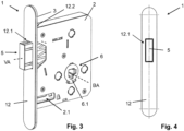
- a boltless short latch lock 1 in the sense of the invention is understood to be a mortise lock for doors comprising a lock case 2 that is open at the front, a faceplate 3 designed for mounting the mortise lock on a door leaf, an actuating mechanism 4 accommodated in the lock case 2, a latch 5 and a nut device 6 comprising an inner and outer nut half 6.1, 6.2, wherein the inner nut half 6.1 is operatively connected to the latch 5 via the actuating mechanism 4 and the latch 5 is guided through a first opening 3.1 in the faceplate 3 and is designed to be displaceable along a locking axis VA between a locking position and an unlocking position.
- the lock case 2 is preferably designed in several parts and made of metal.
- the actuating mechanism 4, the latch 5 and the nut device 6 are accommodated in the lock case 2.
- the face plate 3 is preferably detachably connected to a shell-shaped part of the lock case 2, and is preferably screwed to it.
- the lock case 2 can also have a lid-shaped part which, together with the shell-shaped part, forms the lock case 2.
- the parts of the lock case 2 can also be detachably connected to one another.
- the lock case 2 is preferably made of a metal sheet.
- the latch 5 can be implemented, for example, in the form of a whisper latch or a magnetic latch.
- the latch 5 can also be designed to be rotatable, so that the latch lock 1 according to the invention can be used for a right-hinged or a left-hinged door.
- the latch 5 accommodated in the boltless, short latch lock 1 can then be converted accordingly.
- the lock case 2 is adapted in terms of its dimensions to the lock cases usually used for short, latch-less latch locks 1.
- it has a length of between 90mm and 100mm, a width of 80mm to 90mm and a depth of between 14mm and 20mm.
- the length is 95mm, the width 83.4mm and the depth 15.4mm.
- the faceplate 3 has a faceplate length SL that is less than 200 mm, preferably less than 150 mm.
- the arrangement of the follower device 6 in the lock case 2 in relation to the faceplate 3 and the latch 5 is designed in accordance with the European handle standard.
- the faceplate 3, for example, has a faceplate width SB of 20 mm.
- the inner nut half 6.1 is designed to receive a first actuating polygon in a rotationally fixed manner (not shown in the figures) and the outer nut half 6.2 is designed to receive a second actuating polygon in a rotationally fixed manner (not shown in the figures).
- the inner nut half 6.1 can be connected to an inner handle in a rotationally fixed manner via the first actuating polygon.
- the outer nut half 6.2 can be connected to an outer handle in a rotationally fixed manner via the second actuating polygon. Neither handles nor an actuating polygon are shown in the figures.
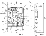
- the actuating mechanism 4 is designed to convert a rotary movement of the first nut half 6.1 about an actuating axis BA into a translatory movement of the latch 5 along the locking axis VA.
- the Figures 7 to 10 The latch 5 shown, designed as a whisper latch, is preferably pre-tensioned by a spring element 5.1, and the spring element 5.1 applies a pre-tension to the latch 5 along the locking axis VA, so that the latch 5 assumes the locking position in which the free end of the latch 5 protrudes outwards from the lock case 2 or through the first opening 3.1 in the faceplate 3 along the locking axis VA and can be brought into operative connection with a strike plate in the door frame or the door casing.
- the latch 5 can be pushed into the lock case 2 against the pre-tension by applying a force from the outside, or it can be pulled into the lock case along the locking axis VA via the actuating mechanism 4, until it assumes the unlocking position in which the latch 3 is largely received in the faceplate 3 or the subsequent lock case 2.
- the latch 5 is moved into the unlocking position when a turning or rotational movement is initiated in the inner nut half 6.1 against the preload of the spring element 5.1 along the locking axis VA, in such a way that the free end of the latch 5 is preferably flush with the outside of the faceplate 3.
- the latch 5 can always be moved from the locking position to the unlocking position and vice versa by initiating a turning or rotational movement in the inner nut half 6.1.
- a nut coupling 8 is provided for the mechanical coupling of the two nut halves 6.1, 6.2, with which a rotationally fixed coupling can be established between the inner and outer nut halves 6.1, 6.2 in a coupling position, whereas in a free-running position the inner and outer nut halves 6.1, 6.2 are decoupled from one another, i.e. the outer nut half 6.2 can rotate freely independently of the inner nut half 6.1.
- the nut coupling 8 has a nut coupling body 8.1 in which at least the outer nut half 6.2 is mounted so as to be rotatable about the actuation axis BA.
- the inner nut half 6.1 is preferably connected in a rotationally fixed manner to the nut coupling body 8.1 and the operative connection with the actuation mechanism 4 is established via the nut coupling body 8.1.
- the inner nut half 6.1 is connected to the nut coupling body 8.1 in such a rotationally fixed manner that the inner nut half 6.1 and thus also the nut coupling body 8.1 can be pivoted within a predetermined rotation angle range.
- the nut coupling 8 is therefore not only designed for the mechanical coupling of the inner and outer nut halves 6.1, 6.2, but also for the rotationally fixed reception of the inner nut half 6.1 and for establishing an operative connection with the actuating mechanism 4.
- the nut coupling body 8.1 is, for example, ring-shaped and extends concentrically around the actuation axis BA, wherein the nut coupling body 8.1 is pivotably mounted around the actuation axis BA in the lock case 2 in order to provide rotation or pivotability of the inner nut half 6.1.
- the nut coupling body 8.1 also extends concentrically around the inner and outer nut halves 6.1, 6.2, which are arranged parallel to one another, wherein the outer nut half 6.2, for example, engages at least in sections in a recess in the inner nut half 6.1 that is concentric to the actuation axis BA.
- the position of the predetermined angle of rotation range is preferably designed to be adjustable in order to adjust the center position of the handles that are connected in a rotationally fixed manner to the nut device 6.
- this so-called “handle center position” can be set by adjusting the rotational position of the nut coupling body 8.1. This also allows the center position of the handles that are connected in a rotationally fixed manner to the nut device 6 to be readjusted after installation on the door.
- the nut coupling body 8.1 has a radially protruding flange-like stop 8.2, which rests against an adjustable contact point, wherein the nut coupling body 8.1, which is mounted so as to be rotatable about the actuation axis BA, is pre-tensioned against the adjustable contact point by means of a spring element 8.3 and the flange-like protruding stop 8.2 thereby comes to rest against it.
- the contact position specified by the adjustable contact point can be adjusted by means of an adjusting element 9, wherein the adjusting element 9 can still be actuated from the outside via a second opening 3.2 in the faceplate 3 even after it has been mounted on the door.
- the adjusting element 9 is formed, for example, by an adjusting screw which is arranged in the lock housing 2 in such a way that the free end of the adjusting screw forms the adjustable contact point directly or indirectly and the head of the adjusting screw can be actuated using a wrench via the second opening 3.2 in the faceplate 3.
- the longitudinal axis of the adjusting screw runs, for example, tangentially to the ring-shaped nut coupling body 8.1.
- the setting or readjustment of the "handle middle position" can advantageously be carried out outside the latch lock 1 via the second opening 3.2 in the faceplate 3. This means that no dismantling of the latchless, short latch lock 1 according to the invention is required for this purpose.
- the nut coupling body 8.1 is designed to accommodate and guide a coupling pin 8.4 at least in sections along a longitudinal axis of the coupling pin 8.4 that runs radially to the actuation axis BA, wherein the coupling pin 8.4 is preferably arranged in a coupling plane that runs perpendicular to the actuation axis BA and between the two nut halves 6.1, 6.2 accommodated in the nut coupling body 8.1 and is preloaded radially upwards via a spring element. Due to the preload, the coupling pin 8.4 protrudes radially outwards from the top or outside of the nut coupling body 8.1.
- the coupling pin 8.4 is dimensioned and accommodated in the nut coupling body 8.1 in such a way that it is aligned with a coupling recess in the outer nut half 6.2 that runs radially to the actuation axis BA, namely in the locking position of the latch 5, i.e. when the handles are not actuated.
- At least one electromechanical actuating device 7 accommodated in the lock case 2 is provided with at least one actuating element 7.1 for actuating the nut coupling 8, and the coupling pin 8.4 can be moved from an uncoupled position to a coupled position and vice versa by means of the actuating element 7.1.
- the coupling pin 8.4 is preferably guided in a flange-like, radially upwardly projecting body section of the nut coupling body 8.1.
- the coupling pin 8.4 In the uncoupled position, the coupling pin 8.4 is located outside the coupling recess of the outer nut half 6.2 and protrudes radially outwards from the nut coupling body 8.1 with its free upper end, in such a way that the opposite free lower end of the coupling pin 8.4 is completely accommodated in the nut coupling body 8.1.
- the coupling pin 8.4 therefore does not engage in the coupling recess of the outer nut half 6.2, i.e. there is no rotationally fixed connection between the inner and outer nut halves 6.1, 6.2 and thus the outer nut half 6.2 and the latch 5.
- the outer nut half 6.2 mounted in the nut coupling body 8.1 can rotate freely about the actuating axis BA in the uncoupled position, i.e. it is in freewheel mode.
- the coupling pin 8.4 is moved by means of the actuating element 7.1 against the preload radially in the direction of the actuating axis BA into the coupling recess of the outer nut half 6.2 and thereby comes into engagement with the outer nut half 6.2.
- the coupling pin 8.4 In the coupled position, the coupling pin 8.4 is mostly pushed into the nut coupling body 8.1, only the free upper end of the coupling pin 8.4 still protrudes slightly radially outwards over the outer or upper side of the nut coupling body 8.1 and is in contact with the actuating element 7.1, which for this purpose has a front-side contact and guide surface 7.4.
- the front contact and guide surface 7.4 preferably runs concentrically to the actuation axis BA and forms a contact and guide surface 7.4 with a curved cross-section, by means of which the coupling pin 8.4 is always held in the coupled position when rotating or pivoting about the actuation axis BA.
- the effective range of the contact and guide surface 7.4 is adapted to the specified angle of rotation range of the nut device 6.
- the electromechanical actuating device 7 comprises a drive element 7.2 and an electromotive drive unit 7.3, which are arranged one behind the other along a coupling axis KA.
- the electromotive drive unit 7.3 is designed for the motor drive of the actuating element 7.1 along the coupling axis KA, ie perpendicular to the actuating axis BA and also perpendicular to the locking axis VA of the latch 5.
- the electromechanical actuating device 7 can be transferred from a freewheel position to a coupling position and vice versa, namely by a corresponding controlled movement of the actuating element 7.1 along the coupling axis KA.
- a control device 10 is accommodated in the lock case 2, by means of which the freewheel position and clutch position can be specified and controlled accordingly.
- an electrically controllable actuator unit or a correspondingly designed actuating element can also be provided.
- the control device 10 is formed, for example, by a control board with an integrated control circuit located thereon, which is preferably arranged above the latch 5 in the lock housing 2 and is preferably connected by wire to the electric motor drive unit 7.3.
- a power supply unit 11 is accommodated in the lock case 2 and is also connected to both the control device 10 and the electromotive drive unit 7.3 via corresponding connecting cables routed in the lock case 2.
- the energy supply unit 11 is formed by at least one battery unit or rechargeable battery unit, which is exchangeably accommodated in a receiving space 2.1 in the lock case 2 that is open to the faceplate 3.
- the receiving space 2.1 is preferably accessible from the outside via a third opening 3.3 in the faceplate 3 of the boltless, short latch lock 1 according to the invention, so that the battery unit or rechargeable battery unit forming the energy supply unit 11 can be replaced when installed.
- the third opening 3.3 in the faceplate 3 can preferably be closed by means of a cover element 3.4.
- the cover element 3.4 is accommodated in the third opening 3.3 and clamped therein.
- FIG. 7 , 9 and 10 a schematic side view of the boltless, short latch lock 1 is shown with the lock housing 2 opened at the side, wherein the actuating element 7.1 is shown in the free-running state and in a first and second coupling position.
- the actuating element 7.1 In the free-running position, the actuating element 7.1 is arranged at a distance from the free upper end of the coupling pin 8.4, whereas in the first and second coupling position according to the Figures 9 the free upper end of the coupling pin 8.4 rests on the actuating element 7.1 and in Figure 10 is inserted into the nut coupling body 8.1 to establish the mechanical coupling between the inner and outer nut halves 6.1, 6.2.
- the actuating element 7.1 is formed by a substantially L-shaped coupling body, the shorter body section 7.11 of which extends along the coupling axis KA, whereas the adjoining longer body section 7.12 runs perpendicular to it.
- the two body sections 7.11, 7.12 form the L-shaped coupling body due to their differences in length, with the end face facing away from the electromotive drive unit 7.3 and running radially to the actuating axis BA forming the contact and guide surface 7.4, against which the free upper end of the coupling pin 8.4 rests in the coupled position or the coupling position of the electromechanical actuating device 7.
- the shorter body section 7.12 also has a through hole extending along the coupling axis KA, in which the drive element 7.2, preferably designed as a drive spindle, is accommodated.
- the through hole of the shorter body section 7.12 has an internal thread which is in engagement with an external thread of the drive spindle 7.2.
- the actuating element 7.1 thus forms a slide element which can be moved by motor along the coupling axis KA by means of the drive spindle 7.2 by appropriately controlling the electromotive drive unit 7.3.
- a replaceable faceplate 12 is provided, the dimensions of which are preferably identical to the dimensions of the faceplate 3, so that the faceplate 12, when mounted, is congruent with the outside of the faceplate 3.
- the faceplate 12 has an opening 12.1 for the passage of the free end of the latch 5, which is preferably designed to be identical to the first opening 3.1 in the faceplate 3 and is flush with it.
- the faceplate 12 is designed for clamping attachment to the faceplate 3 and for this purpose has two clip-like clamping elements 12.1, 12.2, which can each be passed through a fourth or fifth opening 3.4, 3.5 in the faceplate 3 and clip into a lower and upper recess 2.2, 2.3 in the lock case 2.
- the faceplate 12 can thus be plugged onto the faceplate 3 and is releasably secured to the faceplate 3 via the clip-like clamping elements 12.1, 12.2.
- the faceplate 12 preferably has a surface structure or surface appearance on the visible side that matches the door surface or is adapted to the corresponding veneer or surface design of the door. With the exception of the free end of the latch 3, the faceplate 12 thus covers the area of the faceplate 12 that is still visible from the outside after installation on the door leaf.
- the faceplate 3 has further through-holes for mounting the faceplate 3 on the door leaf, which can be designed depending on the mounting situation.
- the inner nut half 6.1 or the inner handle operatively connected to it can also be designed to be lockable.
- an additional locking mechanism can be provided to lock the inner nut half 6.1, which is accommodated either in the lock case 2 or in the inner handle.
- the locking of the inner nut half 6.1 is preferably carried out indirectly, namely by attaching the handle to the lock case 2 and/or to a rosette arrangement of the door fitting that includes the handle.
- the outer nut half 6.2 is advantageously also locked or is in freewheel mode due to the described design of the nut coupling 4.
Landscapes
- Engineering & Computer Science (AREA)
- Structural Engineering (AREA)
- Lock And Its Accessories (AREA)
Applications Claiming Priority (1)
| Application Number | Priority Date | Filing Date | Title |
|---|---|---|---|
| DE102023109593.5A DE102023109593A1 (de) | 2023-04-17 | 2023-04-17 | Einsteckschloss für Türen |
Publications (1)
| Publication Number | Publication Date |
|---|---|
| EP4459086A1 true EP4459086A1 (fr) | 2024-11-06 |
Family
ID=92908870
Family Applications (1)
| Application Number | Title | Priority Date | Filing Date |
|---|---|---|---|
| EP24164862.5A Pending EP4459086A1 (fr) | 2023-04-17 | 2024-03-20 | Serrure encastrée pour portes |
Country Status (2)
| Country | Link |
|---|---|
| EP (1) | EP4459086A1 (fr) |
| DE (1) | DE102023109593A1 (fr) |
Citations (5)
| Publication number | Priority date | Publication date | Assignee | Title |
|---|---|---|---|---|
| DE20207283U1 (de) * | 2002-01-14 | 2002-08-08 | Grundmann Beschlagtechnik GmbH, Rohrbach an der Gölsen | Türschloss |
| EP1617019B1 (fr) | 2004-07-15 | 2010-10-06 | Dorma GmbH + Co. KG | Serrure de porte électromécanique |
| DE202013005488U1 (de) * | 2013-06-19 | 2014-09-22 | Wilhelm Rademacher | Türschloss |
| US20190119951A1 (en) * | 2017-10-20 | 2019-04-25 | Taiwan Fu Hsing Industrial Co., Ltd. | Door lock and method of installation and un-installation of the same |
| WO2020023652A1 (fr) * | 2018-07-24 | 2020-01-30 | Schlage Lock Company Llc | Mécanisme d'embrayage modulaire |
Family Cites Families (4)
| Publication number | Priority date | Publication date | Assignee | Title |
|---|---|---|---|---|
| DE20102279U1 (de) * | 2001-01-22 | 2001-04-12 | Wendl, Richard, 91249 Weigendorf | Elektronisch steuerbare Schließvorrichtung |
| DE102008014488B4 (de) * | 2008-03-17 | 2013-11-07 | Dorma Gmbh + Co. Kg | Türschloss mit ein- und auskoppelbarer Handhabe |
| DE202009016534U1 (de) * | 2009-12-04 | 2010-03-04 | Sächsische Schloßfabrik GmbH | Schloss |
| DE102011082229B4 (de) * | 2011-09-07 | 2020-07-09 | Bks Gmbh | Schloss |
-
2023
- 2023-04-17 DE DE102023109593.5A patent/DE102023109593A1/de active Pending
-
2024
- 2024-03-20 EP EP24164862.5A patent/EP4459086A1/fr active Pending
Patent Citations (5)
| Publication number | Priority date | Publication date | Assignee | Title |
|---|---|---|---|---|
| DE20207283U1 (de) * | 2002-01-14 | 2002-08-08 | Grundmann Beschlagtechnik GmbH, Rohrbach an der Gölsen | Türschloss |
| EP1617019B1 (fr) | 2004-07-15 | 2010-10-06 | Dorma GmbH + Co. KG | Serrure de porte électromécanique |
| DE202013005488U1 (de) * | 2013-06-19 | 2014-09-22 | Wilhelm Rademacher | Türschloss |
| US20190119951A1 (en) * | 2017-10-20 | 2019-04-25 | Taiwan Fu Hsing Industrial Co., Ltd. | Door lock and method of installation and un-installation of the same |
| WO2020023652A1 (fr) * | 2018-07-24 | 2020-01-30 | Schlage Lock Company Llc | Mécanisme d'embrayage modulaire |
Also Published As
| Publication number | Publication date |
|---|---|
| DE102023109593A1 (de) | 2024-10-17 |
Similar Documents
| Publication | Publication Date | Title |
|---|---|---|
| EP0537531B1 (fr) | Serrure pour porte | |
| DE29820711U1 (de) | Drehriegelverschluß mit Zugeinrichtung | |
| EP0677131A1 (fr) | Dispositif de fermeture pour portes de boitiers ou de placards. | |
| DE202021100165U1 (de) | Verstellstruktur für Schlosskern und intelligentes Schloss | |
| EP0175049B1 (fr) | Tourniquet susceptible d'être manoeuvré par une clé à tube | |
| DE112007001826T5 (de) | Schlossmechanismus | |
| EP4438836B1 (fr) | Système de fermeture et porte ou fenêtre dotée d'un tel système de fermeture | |
| EP0799957A2 (fr) | Barre anti-panique réversible pour portes de secours | |
| EP1056915A1 (fr) | Serrure | |
| EP2708687B1 (fr) | Kit pour la fabrication de différentes variantes d'une poignée d'actionnement | |
| DE102023109593A1 (de) | Einsteckschloss für Türen | |
| EP3670799A1 (fr) | Dispositif de verrouillage | |
| DE202019105467U1 (de) | Gebäudeöffnung mit einer Einrichtung zum Öffnen und Schließen sowie Ver- und Entriegel von Gebäudeöffnungen | |
| EP1651831B1 (fr) | Ensemble constituant une partie d'un mecanisme de fermeture | |
| EP0239855B1 (fr) | Serrure pour porte, fenêtre ou similaire | |
| WO2023011874A1 (fr) | Poignée de porte | |
| DE202021100558U1 (de) | Verriegelungseinrichtung für ein Betätigungshandhabenpaar einer Tür | |
| DE3205054C2 (fr) | ||
| WO2021224187A1 (fr) | Ensemble charnière à actionnement commun | |
| DE10118049C2 (de) | Türöffner mit verschwenkbar gelagerter Falle | |
| EP1116838A1 (fr) | Ferrure de protection pour porte | |
| DE9104766U1 (de) | Antipaniktürschloß | |
| EP4253698B1 (fr) | Système de fermeture pour une porte et agencement de porte doté d'un système de fermeture | |
| DE3422057C2 (fr) | ||
| DE102018003810B4 (de) | Verriegelungskonsole zum Ver- und Entriegeln eines Flügels |
Legal Events
| Date | Code | Title | Description |
|---|---|---|---|
| PUAI | Public reference made under article 153(3) epc to a published international application that has entered the european phase |
Free format text: ORIGINAL CODE: 0009012 |
|
| STAA | Information on the status of an ep patent application or granted ep patent |
Free format text: STATUS: THE APPLICATION HAS BEEN PUBLISHED |
|
| AK | Designated contracting states |
Kind code of ref document: A1 Designated state(s): AL AT BE BG CH CY CZ DE DK EE ES FI FR GB GR HR HU IE IS IT LI LT LU LV MC ME MK MT NL NO PL PT RO RS SE SI SK SM TR |
|
| STAA | Information on the status of an ep patent application or granted ep patent |
Free format text: STATUS: REQUEST FOR EXAMINATION WAS MADE |
|
| 17P | Request for examination filed |
Effective date: 20250506 |