EP4459092A2 - Dispositif de détection pour un véhicule - Google Patents
Dispositif de détection pour un véhicule Download PDFInfo
- Publication number
- EP4459092A2 EP4459092A2 EP24195156.5A EP24195156A EP4459092A2 EP 4459092 A2 EP4459092 A2 EP 4459092A2 EP 24195156 A EP24195156 A EP 24195156A EP 4459092 A2 EP4459092 A2 EP 4459092A2
- Authority
- EP
- European Patent Office
- Prior art keywords
- sensor device
- vehicle
- activation
- sensor
- movable part
- Prior art date
- Legal status (The legal status is an assumption and is not a legal conclusion. Google has not performed a legal analysis and makes no representation as to the accuracy of the status listed.)
- Pending
Links
Images


Classifications
-
- E—FIXED CONSTRUCTIONS
- E05—LOCKS; KEYS; WINDOW OR DOOR FITTINGS; SAFES
- E05F—DEVICES FOR MOVING WINGS INTO OPEN OR CLOSED POSITION; CHECKS FOR WINGS; WING FITTINGS NOT OTHERWISE PROVIDED FOR, CONCERNED WITH THE FUNCTIONING OF THE WING
- E05F15/00—Power-operated mechanisms for wings
- E05F15/70—Power-operated mechanisms for wings with automatic actuation
- E05F15/73—Power-operated mechanisms for wings with automatic actuation responsive to movement or presence of persons or objects
-
- B—PERFORMING OPERATIONS; TRANSPORTING
- B62—LAND VEHICLES FOR TRAVELLING OTHERWISE THAN ON RAILS
- B62D—MOTOR VEHICLES; TRAILERS
- B62D33/00—Superstructures for load-carrying vehicles
- B62D33/02—Platforms; Open load compartments
- B62D33/023—Sideboard or tailgate structures
- B62D33/027—Sideboard or tailgate structures movable
- B62D33/0273—Movable tailboards for vehicles comprising non-movable sideboards, e.g. pick-up trucks
-
- B—PERFORMING OPERATIONS; TRANSPORTING
- B62—LAND VEHICLES FOR TRAVELLING OTHERWISE THAN ON RAILS
- B62D—MOTOR VEHICLES; TRAILERS
- B62D33/00—Superstructures for load-carrying vehicles
- B62D33/02—Platforms; Open load compartments
- B62D33/023—Sideboard or tailgate structures
- B62D33/027—Sideboard or tailgate structures movable
- B62D33/03—Sideboard or tailgate structures movable by swinging down
-
- E—FIXED CONSTRUCTIONS
- E05—LOCKS; KEYS; WINDOW OR DOOR FITTINGS; SAFES
- E05F—DEVICES FOR MOVING WINGS INTO OPEN OR CLOSED POSITION; CHECKS FOR WINGS; WING FITTINGS NOT OTHERWISE PROVIDED FOR, CONCERNED WITH THE FUNCTIONING OF THE WING
- E05F15/00—Power-operated mechanisms for wings
- E05F15/40—Safety devices, e.g. detection of obstructions or end positions
-
- E—FIXED CONSTRUCTIONS
- E05—LOCKS; KEYS; WINDOW OR DOOR FITTINGS; SAFES
- E05Y—INDEXING SCHEME ASSOCIATED WITH SUBCLASSES E05D AND E05F, RELATING TO CONSTRUCTION ELEMENTS, ELECTRIC CONTROL, POWER SUPPLY, POWER SIGNAL OR TRANSMISSION, USER INTERFACES, MOUNTING OR COUPLING, DETAILS, ACCESSORIES, AUXILIARY OPERATIONS NOT OTHERWISE PROVIDED FOR, APPLICATION THEREOF
- E05Y2400/00—Electronic control; Electrical power; Power supply; Power or signal transmission; User interfaces
- E05Y2400/10—Electronic control
- E05Y2400/44—Sensors not directly associated with the wing movement
-
- E—FIXED CONSTRUCTIONS
- E05—LOCKS; KEYS; WINDOW OR DOOR FITTINGS; SAFES
- E05Y—INDEXING SCHEME ASSOCIATED WITH SUBCLASSES E05D AND E05F, RELATING TO CONSTRUCTION ELEMENTS, ELECTRIC CONTROL, POWER SUPPLY, POWER SIGNAL OR TRANSMISSION, USER INTERFACES, MOUNTING OR COUPLING, DETAILS, ACCESSORIES, AUXILIARY OPERATIONS NOT OTHERWISE PROVIDED FOR, APPLICATION THEREOF
- E05Y2400/00—Electronic control; Electrical power; Power supply; Power or signal transmission; User interfaces
- E05Y2400/10—Electronic control
- E05Y2400/44—Sensors not directly associated with the wing movement
- E05Y2400/446—Vehicle state sensors, e.g. parked or inclination
-
- E—FIXED CONSTRUCTIONS
- E05—LOCKS; KEYS; WINDOW OR DOOR FITTINGS; SAFES
- E05Y—INDEXING SCHEME ASSOCIATED WITH SUBCLASSES E05D AND E05F, RELATING TO CONSTRUCTION ELEMENTS, ELECTRIC CONTROL, POWER SUPPLY, POWER SIGNAL OR TRANSMISSION, USER INTERFACES, MOUNTING OR COUPLING, DETAILS, ACCESSORIES, AUXILIARY OPERATIONS NOT OTHERWISE PROVIDED FOR, APPLICATION THEREOF
- E05Y2400/00—Electronic control; Electrical power; Power supply; Power or signal transmission; User interfaces
- E05Y2400/10—Electronic control
- E05Y2400/45—Control modes
-
- E—FIXED CONSTRUCTIONS
- E05—LOCKS; KEYS; WINDOW OR DOOR FITTINGS; SAFES
- E05Y—INDEXING SCHEME ASSOCIATED WITH SUBCLASSES E05D AND E05F, RELATING TO CONSTRUCTION ELEMENTS, ELECTRIC CONTROL, POWER SUPPLY, POWER SIGNAL OR TRANSMISSION, USER INTERFACES, MOUNTING OR COUPLING, DETAILS, ACCESSORIES, AUXILIARY OPERATIONS NOT OTHERWISE PROVIDED FOR, APPLICATION THEREOF
- E05Y2400/00—Electronic control; Electrical power; Power supply; Power or signal transmission; User interfaces
- E05Y2400/10—Electronic control
- E05Y2400/52—Safety arrangements associated with the wing motor
- E05Y2400/53—Wing impact prevention or reduction
- E05Y2400/54—Obstruction or resistance detection
-
- E—FIXED CONSTRUCTIONS
- E05—LOCKS; KEYS; WINDOW OR DOOR FITTINGS; SAFES
- E05Y—INDEXING SCHEME ASSOCIATED WITH SUBCLASSES E05D AND E05F, RELATING TO CONSTRUCTION ELEMENTS, ELECTRIC CONTROL, POWER SUPPLY, POWER SIGNAL OR TRANSMISSION, USER INTERFACES, MOUNTING OR COUPLING, DETAILS, ACCESSORIES, AUXILIARY OPERATIONS NOT OTHERWISE PROVIDED FOR, APPLICATION THEREOF
- E05Y2400/00—Electronic control; Electrical power; Power supply; Power or signal transmission; User interfaces
- E05Y2400/65—Power or signal transmission
- E05Y2400/66—Wireless transmission
- E05Y2400/664—Wireless transmission by radio waves
-
- E—FIXED CONSTRUCTIONS
- E05—LOCKS; KEYS; WINDOW OR DOOR FITTINGS; SAFES
- E05Y—INDEXING SCHEME ASSOCIATED WITH SUBCLASSES E05D AND E05F, RELATING TO CONSTRUCTION ELEMENTS, ELECTRIC CONTROL, POWER SUPPLY, POWER SIGNAL OR TRANSMISSION, USER INTERFACES, MOUNTING OR COUPLING, DETAILS, ACCESSORIES, AUXILIARY OPERATIONS NOT OTHERWISE PROVIDED FOR, APPLICATION THEREOF
- E05Y2400/00—Electronic control; Electrical power; Power supply; Power or signal transmission; User interfaces
- E05Y2400/80—User interfaces
- E05Y2400/85—User input means
- E05Y2400/856—Actuation thereof
- E05Y2400/858—Actuation thereof by body parts, e.g. by feet
-
- E—FIXED CONSTRUCTIONS
- E05—LOCKS; KEYS; WINDOW OR DOOR FITTINGS; SAFES
- E05Y—INDEXING SCHEME ASSOCIATED WITH SUBCLASSES E05D AND E05F, RELATING TO CONSTRUCTION ELEMENTS, ELECTRIC CONTROL, POWER SUPPLY, POWER SIGNAL OR TRANSMISSION, USER INTERFACES, MOUNTING OR COUPLING, DETAILS, ACCESSORIES, AUXILIARY OPERATIONS NOT OTHERWISE PROVIDED FOR, APPLICATION THEREOF
- E05Y2900/00—Application of doors, windows, wings or fittings thereof
- E05Y2900/50—Application of doors, windows, wings or fittings thereof for vehicles
- E05Y2900/53—Type of wing
- E05Y2900/546—Tailboards, tailgates or sideboards opening upwards
Definitions
- the invention relates to a sensor device for a vehicle according to the preamble of the independent device claim.
- the invention also relates to an actuating device for a movable part, in particular a tailgate, of a vehicle according to the independent device claim.
- the invention relates to a method for operating a sensor device according to the preamble of the independent method claim.
- Known sensor devices for operating a movable part of a vehicle usually have sensors that can exchange information with the vehicle's surroundings.
- Contactless capacitive sensors are often used as sensors.
- the operation of such sensors proves to be difficult because the capacitive field can easily be distorted by dirt.
- capacitive sensors require relatively complex control.
- such sensor devices are usually limited in their functionality.
- the object of the present invention to at least partially overcome the disadvantages described above.
- the invention provides a sensor device for a vehicle, which has a control unit for actuating a movable part, in particular a tailgate, of the vehicle, and a sensor unit for monitoring at least a first activation area of the movable part of the vehicle, wherein the control unit is designed to actuate the movable part of the vehicle when at least one activation action of a user in the first activation area has been detected by the sensor unit.
- the sensor unit is designed to to detect at least one activation action of the user using electromagnetic waves in the radio frequency range (radar waves).
- the sensor device can be designed in the form of an individually manageable module unit, for example in the form of a chip, preferably a radar chip, which can be attached to the motor vehicle in particular as a coherent structural unit.
- the sensor device can advantageously be arranged directly in the tailgate or in an actuating device for the tailgate or in the area of an emblem or can be installed there so that it is protected from the outside and/or invisibly.
- a sensor device can be installed at a distance from the tailgate in the area of a license plate, a bumper or a diffuser of the vehicle.
- the sensor unit can also be arranged in a concealed manner there.
- the sensor device according to the invention can be in a communication connection with a locking device and/or a drive device of the tailgate of the vehicle in order to control the movable part, i.e. the tailgate, accordingly.
- the control unit of the sensor device can send different control signals for locking, unlocking, opening and/or closing the tailgate depending on the detected activation action to the locking device and/or the drive device of the tailgate.
- the sensor device in the sense of the invention can also be in a communication connection with a security device of the vehicle in order to verify a user's authorization to operate moving parts of the vehicle.
- the sensor device itself can carry out a security query.
- a wireless connection for example by means of radio waves, or a connection via a bus can be used for the communication connection with the security device, which can be carried out using the control unit of the sensor device.
- the sensor device can thus form part of a keyless go system or a keyless entry system of the vehicle.
- the sensor device can form a single, coherent modular unit that can even be handled one-handed for easy installation on the vehicle.
- the invention recognizes that the sensor units that use radar waves to exchange information with the vehicle's surroundings are increasingly being used in various assistance systems in vehicles. Therefore, the vehicles usually have suitable electronics and corresponding control software.
- a sensor device which detects corresponding activation actions of a user in the first activation range with the aid of electromagnetic waves in the radio frequency range or radar waves.
- a corresponding activation action can be provided for a specific operation for operating the movable part.
- Radar waves can be used to provide not only precise distance measurement, but also speed measurement and/or angle measurement.
- radar waves can be used to detect different, even complex gestures as well as 2D and/or 3D movement patterns.
- the activation range including the bandwidth and the range of the sensor unit, can be set in a simple manner, for example using a corresponding transmission frequency and/or transmission pulse duration, for example changing at an interval. This makes such a sensor unit advantageously suitable for detecting different activation actions.
- Such a sensor device is also relatively resistant to environmental influences.
- a sensor device that uses radar waves is suitable for operating the movable part of the vehicle, such as a tailgate.
- the sensor device within the scope of the invention can use its own sensor unit to detect the at least one activation action of the user using radar waves.
- the sensor device can use the existing sensors of the vehicle, for example an assistance system of the vehicle, to monitor a first activation area for at least one activation action by the user using electromagnetic waves in the radio frequency range.
- An assistance system for automated or autonomous driving, parking and/or reversing is conceivable as a corresponding assistance system of the vehicle.
- different assistance systems of the vehicle are compatible with the sensor device according to the invention, which have an activation area or detection area in the rear area of the vehicle.
- the sensor device with the sensor unit according to the invention can provide a corresponding sensor system for at least one assistance system of the vehicle.
- the movable part of the vehicle is usually operated when the vehicle is stationary and the assistance systems of the vehicle are usually activated when the vehicle is moving, it can be advantageous if the sensor device is used, depending on the speed of the vehicle, either to operate the movable part of the vehicle or for assisted and/or autonomous driving of the vehicle.
- the operation of the movable part of the vehicle can be carried out safely, reliably and conveniently. Easy assembly and control of the sensor device can be ensured.
- the resources within the sensor device and the vehicle can be utilized in an advantageous manner and a sensor device with an extended fictionality can be provided.
- the invention can provide for a sensor device that the control unit is designed to control at least one assistance system of the vehicle or can at least contribute to this.
- the control unit can thus be provided with an extended functionality.
- the control unit can make the sensor unit available in at least one operating mode of the sensor device for the needs of the assistance system in order to record information such as the distance, the speed and/or the angular orientation to other stationary and/or moving road users.
- control unit can be brought into a communication connection with a vehicle-side control device of an assistance system of the vehicle.
- the control unit can thus transmit the information from the sensor unit (sensor data) to the vehicle-side control device, for example using radio waves or via a bus.
- This information can be used within the assistance system without having to provide separate sensors for the assistance system, or at least to support these sensors.
- assistance systems are conceivable as assistance systems within the meaning of the invention, which are controlled using the control unit and/or supplied with sensor data: assistance systems for automated or autonomous driving, parking and/or reversing.
- assistance systems usually have activation areas or monitoring areas that extend in the rear area of the vehicle (rear area).
- the sensor device for actuating the movable part that is arranged in the rear area of the vehicle, such as the tailgate, can thus provide such a monitoring area behind the vehicle using its own sensor unit.
- control unit can receive the sensor data of an assistance system of the vehicle via the communication connection with the vehicle-side control device in order to use this data.
- the invention can provide for a sensor device that the sensor unit for a distance measurement, a speed measurement and/or a Angle measurement is carried out within the first activation area and/or a second activation area and/or a third activation area. In this way, information can be recorded using the sensor unit, which can be used to control at least one assistance system of the vehicle.
- the invention can provide for a sensor device to have at least a first operating mode, a second operating mode and/or a third operating mode.
- the first operating mode can advantageously be used to actuate the movable part of the vehicle, for example to control a locking device and/or a drive device of a rear hatch of the vehicle.
- a prerequisite for the first operating mode can advantageously be that the vehicle is stationary or moving at a low speed of less than 3 km/h. This can ensure that the rear hatch of the vehicle is not opened accidentally when the vehicle is being driven.
- the second operating mode of the sensor device can advantageously be activated when the vehicle is moving at a speed between 3 km/h and 30 km/h, in particular between 3 km/h and 20 km/h, preferably between 3 km/h and 10 km/h. This is the speed range in which certain assistance systems can be advantageous, such as a parking aid or the like.
- the second operating mode of the sensor device within the scope of the invention can thus be dedicated to these assistance systems.
- the third operating mode of the sensor device can advantageously be activated when the vehicle is moving at a speed of 10 km/h or more, in particular 20 km/h or more, preferably 30 km/h or more. This is the speed range in which certain assistance systems can also be important, such as an assistance system for reversing or the like.
- the third operating mode of the sensor device can therefore be assigned to these assistance systems within the scope of the invention.
- the invention can provide that certain assistance systems can use the sensor device according to the invention in the second operating mode and other assistance systems can use the sensor device in the third operating mode.
- the invention can provide for a sensor device that in at least one operating mode the sensor device can be operated to detect the at least one activation action of the user in the first activation area.
- the sensor device can thus be used to actuate the movable part of the vehicle.
- the radar-based sensor unit can detect, determine and differentiate between a wide variety of activation actions in the form of gestures or movement patterns, leg and/or foot movements, approaches or simple presences in the first activation area. This can provide increased comfort when actuating the movable part.
- a tailgate as the movable part of the vehicle in the sense of the invention, it can be advantageous for the sensor device to first detect the presence of a user. A security query can then be carried out or initiated.
- Different movement patterns can be provided for unlocking and/or opening the tailgate, for example stroking movements with one hand along the tailgate in different directions, or different leg and/or foot movements, for example kicking movements and/or rocking movements below the rear area with one foot.
- a further movement pattern can be provided for closing and/or locking the tailgate, for example a tapping movement from above towards an outer skin of the tailgate.
- the invention can provide for a sensor device that, in at least one operating mode, the sensor device can be operated for a distance measurement, a speed measurement and/or an angle measurement within the first activation range and/or a second activation range and/or a third activation range. Different information can thus be sensed that can be advantageous for operating an assistance system of the vehicle.
- the invention can provide for a sensor device that, in at least one operating mode, the sensor device can be operated to detect an obstacle when the movable part of the vehicle is actuated. This ensures particularly safe and accident-free actuation of the movable part in order not to damage the movable part or surrounding objects or to endanger people.
- the invention can provide for a sensor device that in at least one operating mode, for example in the first operating mode, the sensor device of the sensor unit is assigned a transmission frequency in the frequency range between 76 GHz and 77 GHz.
- the sensor unit can monitor the surroundings of the vehicle using long-range radar waves (Long Range Radar or LRR) with a relatively narrow bandwidth.
- LRR Long Range Radar
- This can be advantageous for assistance systems with an initial range of up to 250 m.
- a long range can also be advantageous for detecting a user who is approaching the vehicle in order to enable a delay-free process when operating the movable part.
- the sensor unit can be operated in at least one operating mode, for example in the first operating mode, as a pulse radar or as a continuous wave radar (CW radar), for example as a modulated continuous wave radar (FMCW radar).
- CW radar continuous wave radar
- FMCW radar modulated continuous wave radar
- the invention can provide for a sensor device that in at least one operating mode, for example in the second operating mode, the sensor device of the sensor unit is assigned a transmission frequency in the frequency range between 77 GHz and 81 GHz.
- a relatively small transmitting antenna can be used at these frequencies.
- the relatively wide bandwidth ensures a high resolution.
- the sensor unit can monitor the surroundings of the vehicle using short-range radar waves (SRR).
- SRR short-range radar waves
- This can be advantageous for assistance systems with a second range of up to 70 m. But such a range can also be advantageous for detecting a user who is approaching the vehicle, on the one hand in order to limit the monitoring area and yet still enable a quick process when operating the movable part.
- the sensor unit in at least one Operating mode, for example in the second operating mode, as a continuous wave radar, in particular as a modulated continuous wave radar (FMCW radar).
- a continuous wave radar in particular as a modulated continuous wave radar (FMCW radar).
- FMCW radar modulated continuous wave radar
- the invention can provide for a sensor device that in at least one operating mode, for example in the third operating mode, the sensor device of the sensor unit is assigned a transmission frequency in the frequency range between 77 GHz and 81 GHz.
- a relatively small transmission antenna can be used at these frequencies.
- the relatively wide bandwidth ensures high resolution.
- the sensor unit can monitor the surroundings of the vehicle using short-range radar waves (ultra short range radar or USRR).
- This can be advantageous for assistance systems with a third range of up to 30 m. But such a range can also be advantageous for detecting a user who is approaching the vehicle in order to provide a limited monitoring area and still enable a sufficiently fast process when operating the movable part.
- Such transmission frequencies have wavelengths that can pass through layers with certain material thicknesses relatively smoothly.
- the influence of paint layers at such wavelengths is relatively small, so that the sensor device can be adapted to the appearance of the vehicle in an advantageous manner with a high degree of design freedom.
- the sensor unit can be operated in at least one operating mode, for example in the third operating mode, as a continuous wave radar, in particular as a modulated continuous wave radar (FMCW radar).
- FMCW radar modulated continuous wave radar
- the invention can provide for a sensor device that in at least one operating mode of the sensor device of the sensor unit a first bandwidth or a second bandwidth is assigned.
- the bandwidth can determine the width of the respective activation area in a simple manner.
- the respective activation area or the respective monitoring area can be designed in the form of a detection lobe. Different bandwidths can be advantageous for different functions. For example, a narrow activation area is advantageous for distance control for reversing into a parking space.
- a wide activation area can be advantageous for another assistance system or for operating the movable part in order to to enable the most comprehensive possible monitoring of the activation area around the vehicle.
- the invention can provide for a sensor device in which the sensor unit is designed to detect a presence and/or an approach and/or a leg and/or foot movement of the user as the at least one activation action in the first activation area, and/or in which the sensor unit is designed to detect at least a first movement pattern or a second movement pattern by a hand of the user as the at least one activation action in the first activation area.
- the sensor device can thus be used in combination with different technologies for actuating the movable part, in particular the tailgate, of the vehicle.
- the invention can provide for a sensor device that the control unit is designed to query security or to query the user's access authorization, or that the control unit can be brought into a communication connection with a security device of the vehicle in order to verify the user's access authorization.
- the sensor device can thus form part of a keyless go system or a keyless entry system.
- the control unit is designed to actuate the movable part (unlocking and/or opening) when a leg and/or foot movement of the user has been detected as the at least one activation action in the first activation area using the sensor unit.
- This makes it possible to conveniently actuate the movable part.
- This can be advantageous in particular in the case of a tailgate as the movable part of the vehicle if the user is carrying objects in their hands and does not have a free hand. Nevertheless, a specific leg and/or foot movement by the user can ensure that the tailgate is not actuated accidentally, for example by a cat walking past or another accidental movement in the rear area of the vehicle.
- the invention can provide that the control unit is designed to detect the leg and/or foot movement of the user in the form of a movement with one leg of the user towards the movable part and a kicking movement with one foot under the movable part, and/or that the control unit is designed to detect the leg and/or foot movement of the user in the form of a rocking movement with one foot under the movable part.
- a specific sequence for the leg and/or foot movement of the user can thus be defined. In this way, the risk of incorrect operation of the movable part can be significantly reduced.
- control unit is designed to actuate the movable part when a first movement pattern and a second movement pattern have been detected one after the other as the at least one activation action in the first activation area. This makes it possible to actuate the movable part with one hand, which can carry out defined movement patterns using gestures in order to reduce the risk of incorrect actuation of the movable part.
- the invention can provide that the control unit is designed to detect the first movement pattern in the form of a stroking movement with one hand in a first direction along the movable part and the second movement pattern in the form of a stroking movement with one hand in a second direction along the movable part.
- This enables comfortable and safe actuation of the movable part.
- the first direction and the second direction can run essentially horizontally and/or be opposite. The first movement pattern and the second movement pattern can thus enable simple and intuitive actuation of the movable part.
- a sensor device it is possible for a sensor device to have the control unit designed to stop the actuation of the movable part when an obstacle is detected that stands in the way of the actuation of the movable part.
- the movable part can thus be operated safely and the risk of damage to surrounding objects or injuries to living objects in the vicinity of the movable part of the vehicle can be reduced. In other words, This ensures that the movable part is only operated when there is sufficient space for its movement.
- the invention can provide at least one further sensor unit in a sensor device in order to detect the at least one activation action of the user using electromagnetic waves in the optical frequency range or in the infrared range or using a capacitive measurement.
- a combination sensor system can thus be provided within the scope of the sensor device, which can advantageously exploit the advantages of several technologies for certain activation actions.
- the sensor device can be used widely within the scope of the invention and can be combined with different technologies. It is conceivable, for example, that a push button and/or capacitive sensor can be provided in order to close and/or lock the tailgate.
- a further sensor unit with optical detection can also be used to detect certain activation actions of the user.
- the sensor device can be arranged on the movable part, on an emblem, on a license plate, on a bumper or on a diffuser of the vehicle.
- the sensor device can thus be used in the rear area of the vehicle.
- the sensor device can be integrated into existing assistance systems of the vehicle or form further assistance systems that have monitoring areas in the rear area of the vehicle.
- the invention can advantageously provide that the sensor device with the control unit, the sensor unit, and possibly a further sensor unit is designed in the form of a modular unit. This makes it possible to provide simple handling and convenient assembly of the sensor device.
- the invention can provide that the sensor device has a carrier plate for the control unit, the sensor unit, and possibly a further sensor unit. This allows for simple assembly of the sensor device.
- a sensor device can be provided with the sensor unit having at least one transceiver, wherein in particular the transceiver has at least one, preferably two, transmitting antennas and at least one, preferably four, receiving antennas.
- the transceiver can use transmitting antennas to emit radar waves that can be reflected by objects or people.
- the reflected radar waves are received by the receiving antennas and provide information about the objects or people detected as well as their positions, movements or the like.
- the surroundings of the vehicle can thus be analyzed using the transceiver.
- a detailed image of the surroundings of the vehicle and the events around the vehicle can be captured, including defined movement patterns.
- One of the transmitting antennas can emit a defined pattern signal, which is compared with the reflected receiving signal.
- the transmission signal is provided with a vehicle identifier in order to distinguish the own transmission signal from external signals.
- Modulation of the transmission signal is possible as a vehicle identifier.
- the transmission signal can serve as a carrier onto which a useful signal is modulated.
- the amplitude or phase of the transmission signal can serve as a parameter for the modulation.
- the modulation can also be continuous or discrete in time.
- the ID code of the authorized user is used as the useful signal in the modulation.
- the receiving antennas can receive the ID code as a modulated useful signal.
- the control unit can then evaluate the ID code. In this way, the security query can be carried out using the sensor device within the scope of the invention.
- the transmission device can be switched off after the movable part has been actuated.
- the invention can provide for a sensor device that the control unit has at least one microcontroller, wherein in particular the microcontroller has at least one converter, at least one signal processing unit, at least one processor unit, at least one memory unit, at least one interface and/or has at least one connection for communication and/or power supply.
- the microcontroller can process and analyze the information from the sensor unit to ensure different operating modes of the sensor device.
- the invention can provide that a housing is provided for the sensor device in order to accommodate the sensor device in a way that is protected from environmental and/or weather influences.
- a closed unit can be provided that can be handled as a module or a modular unit.
- the housing can completely enclose the sensor device. This means that the sensor device can be particularly protected and safely accommodated.
- the invention can provide that the housing for the sensor device has a cover element, which can advantageously be opened, through which the sensor device can be introduced into the housing. This ensures that the sensor device can be easily assembled.
- the cover element also ensures that the sensor device can be made accessible for repairs.
- the cover element is designed to be removable and/or openable.
- a snap-in connection and/or an articulated connection and/or a labyrinth guide can be provided between the cover element and the housing.
- an opening in an outer skin of the movable part, a license plate, a bumper or a diffuser of the vehicle can be closed by the cover element, and/or that the cover element for the housing can be designed in the form of an emblem of the vehicle.
- a section of an outer skin of the movable part, a license plate, a bumper or a diffuser of the vehicle can thus be arranged in an advantageously protected and unobtrusive manner and can be optimally adapted to the appearance of the vehicle.
- a corresponding locking connection and/or an articulated connection and/or a labyrinth guide can be provided between an inner side of the outer skin of the respective component or an edge of the opening and the housing of the sensor device.
- the housing for the sensor device and/or the cover element can be made of a radar-transparent material, in particular plastic, preferably polymer. This ensures that the propagation of electromagnetic waves in the radio frequency range is undisturbed and the sensor device can be arranged so that it is protected from the effects of the weather.
- the invention can provide that the housing for the sensor device and/or the cover element is/are provided with a coating, preferably with a material thickness of 10 nm to 100 nm, at least in sections.
- the coating can be used to design the external appearance of the sensor device. It is conceivable that the coating can represent decorative strips and/or design surfaces and/or a display and/or an emblem and/or a brand name.
- the coating can be designed, for example, in the form of a lacquer layer, a spray layer or a layer deposited using gas phase deposition or sputtering. This allows the design freedom when implementing the coating to be expanded in an advantageous manner.
- the coating can comprise metal particles, preferably chromium, and/or semiconductor material, preferably silicon. This enables the coating to have a metallic appearance.
- the housing for the sensor device has at least one or more mounting means in order to accommodate the sensor device within the housing in a form-fitting and/or force-fitting manner. This advantageously facilitates the assembly of the sensor device and the replacement of individual components, for example for the purpose of maintenance and/or upgrading of the sensor device.
- the mounting means are designed to clamp the carrier plate of the sensor device within the housing and/or that the mounting means have a circumferential groove for the carrier plate of the sensor device, into which the carrier plate can be inserted. This can simplify the assembly of the sensor device even further.
- the housing for the sensor device has at least one or more fastening means in order to fasten the sensor device in a form-fitting and/or force-fitting manner to an opening on the vehicle and/or to a carrier element on the vehicle.
- the outer skin of the movable part, an emblem, a license plate, a bumper or a diffuser of the vehicle can also serve as the carrier element. This enables the sensor device to be mounted on the vehicle in a simple and convenient manner.
- the fastening means can have locking means that can be brought into mechanical operative connection with corresponding counter-locking means on a vehicle-side opening and/or on a vehicle-side support element, and/or that the fastening means have a guide rail in order to easily insert the sensor device into a vehicle-side opening and/or on a vehicle-side support element. This can make the installation of the sensor device on the vehicle even easier.
- an actuating device for a movable part, in particular a tailgate, of a vehicle which has a sensor device that can be designed as described above.
- the same advantages are achieved that are described above in connection with the sensor device within the scope of the invention. These advantages are fully referred to here.
- sensitive gesture and/or movement pattern recognition can be provided using radar waves. In this way, movement patterns with the hand and/or combined leg and/or foot movements can be recognized using the sensor device. This can enable safe and comfortable operation of the movable part.
- an actuating device can be provided with a sensor device for monitoring at least a first activation area and a further sensor device for monitoring a further switching area of the movable part of the vehicle. This can further improve the functionality of the actuating device.
- different, preferably separable, monitoring areas activation area and switching area
- complicated movement patterns and movements can also be verified, which can expand the functionality of the sensor device in an advantageous way.
- the first activation area has a substantially horizontal extension and that the switching area has a substantially vertical extension.
- the object according to the invention is achieved by a method for operating a sensor device for a vehicle, wherein the sensor device can be designed as described above.
- the sensor device is used in at least one operating mode for detecting at least one activation action of a user in the first activation area is operated in order to actuate a movable part, in particular a tailgate, of the vehicle, and that the sensor device is operated in at least one operating mode for a distance measurement, a speed measurement and/or an angle measurement within the first activation area and/or a second activation area and/or a third activation area in order to control at least one assistance system of the vehicle.
- the same advantages are achieved that were described above in connection with the sensor device and/or actuation device within the scope of the invention. Full reference is made to these advantages here.
- the sensor device can use electromagnetic waves in the radio frequency range (radar waves) to detect the at least one activation action of a user in the first activation area and for a distance measurement, a speed measurement and/or an angle measurement within the first activation area and/or a second activation area and/or a third activation area.
- radar waves electromagnetic waves in the radio frequency range
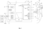
- the Figure 1 shows a sensor device 10 according to the invention, which can be used in a vehicle 100 at several locations, as described below in the Figure 5 is shown.
- the sensor device 10 comprises a control unit 11, which serves to actuate a movable part 101, for example a tailgate 101, of the vehicle 100, for example to lock, unlock, open or close it.
- the control unit 11 can contact a locking device 111 or a drive device 112 of the movable part 101, in particular the tailgate 101, of the vehicle 100 and transmit a corresponding control signal for a corresponding actuation (unlocking, locking, opening, closing) of the movable part 101.
- the sensor device 10 further comprises a sensor unit 12 for monitoring at least a first activation area A1 of the movable part 101 of the vehicle 100.
- the control unit 12 is designed to actuate the movable part 101 of the vehicle 100 when at least one activation action H1, H2, H3, B1, B2 of a user in the first activation area A1 has been detected by the sensor unit 12.
- the sensor unit 12 is designed to detect the at least one activation action H1, H2, H3, B1, B2 of the user using electromagnetic waves in the radio frequency range (radar waves).
- the sensor device according to the invention can preferably be designed to actuate a tailgate 101 of the vehicle 100.
- the sensor device 10 can be arranged directly on the movable part 101, i.e. on the tailgate 101.
- the sensor device 10 can be arranged at an opening in an outer skin of the tailgate 101 and/or on a support element and/or behind the outer skin of the tailgate 101. Since the radio waves can pass through most plastics undisturbed, it is conceivable that the outer skin of the tailgate 101 can be made of a radar-permeable plastic if the sensor device 10 is arranged behind it.
- a housing 20 and/or a cover element 21 for the sensor device 10 can also be made of a radar-permeable plastic.
- a housing 20 for the sensor device 10 and/or a cover element 21 and/or the outer skin of the tailgate 101 can be provided with a coating 22 (cf. the Figures 6 and 7 ) in order to adapt the appearance of the sensor device 10 or the tailgate 101 to the appearance of the vehicle 100.
- the coating 22 can be a paint layer, a spray layer or a layer deposited using gas phase deposition (CVD, PVD) or using sputtering.
- the coating 22 can have a material thickness between 10 nm and 100 nm.
- a sensor device 10 can be arranged behind an emblem 102 of the vehicle 100. It is also conceivable that the sensor device 10 can be arranged or installed at a distance from the tailgate 101, for example in the area of a license plate 103, a bumper 104 and a diffuser. The sensor device 10 can also be arranged openly or concealed there.
- the sensor device 10 in the sense of the invention can be in a communication connection with a locking device 111 and/or a drive device 112 of the tailgate 101 of the vehicle 100 in order to control these devices accordingly and thus to actuate the movable part 101, i.e. the tailgate 101.
- the control unit 11 of the sensor device 10 can thereby send different control signals for locking, unlocking, opening and/or closing the Tailgate 101 transmits H1, H2, H3, B1, B2 depending on the detected activation action.
- the sensor device 10 in the sense of the invention can also be in a communication connection ID with a security device 110 of the vehicle 100 in order to verify a user's authorization to operate the movable part 101 of the vehicle 100. It is also possible for the sensor device 10 itself to carry out a security query.
- the sensor device 10 can thus form part of a keyless go system or a keyless entry system of the vehicle 100.
- a wireless connection for example by means of radio waves, or a wired connection, for example via a CAN bus, LVDS or automotive Ethernet, can be used for the communication connection ID with the security device 110.
- the sensor device 10 uses electromagnetic waves in the radio frequency range or radar waves to actuate the movable part 101, in particular the tailgate 101 (locking, unlocking, opening and/or closing), of the vehicle 100.
- the sensor unit 12 of the sensor device 10 is used to send and receive the radar waves.
- the control unit 11 of the sensor device 10 is used to analyze, evaluate and process the radio waves.
- different activation actions H1, H2, H3, B1, B2 of a user in the first activation area A1 of the sensor device 10 can be detected.
- a corresponding activation action H1, H2, H3, B1, B2 can be provided.
- complicated gestures as well as 2D and/or 3D movement patterns can be recognized.
- a specific activation range A1, A2, A3, comprising the bandwidth W1, W2 and the range D1, D2, D3 of the activation range A1, A2, A3, can be set in a simple manner, for example using a corresponding transmission frequency and/or transmission pulse duration, for example changing at a specific interval, on the sensor unit 12.
- the sensor device 10 can thus set different activation ranges A1, A2, A3.
- Such a sensor device 10 is also relatively resistant to environmental influences.
- the sensor device 10 can use its own sensor unit 12 to detect the at least one activation action H1, H2, H3, B1, B2 of the user.
- the sensor device 10 can use the existing sensors of the vehicle 100, for example an assistance system of the vehicle 100, to monitor at least a first activation area A1 of the vehicle 100 for at least one activation action H1, H2, H3, B1, B2 of the user.
- An assistance system for automated or autonomous driving, parking and/or reversing can serve as a corresponding assistance system of the vehicle 100.
- the sensor device 10 with its own sensor unit 12 can provide a corresponding sensor system for at least one assistance system of the vehicle 100.
- the sensor data of the sensor unit 12 can be used either to actuate the movable part 101 or to control an assistance system of the vehicle 100.
- a strict separation can advantageously be made between these operating modes I, II, III of the sensor device 10 in order to ensure safety in the operation of the vehicle 100. Since the movable part 101 of the vehicle 100 is usually actuated when the vehicle 100 is stationary and the assistance systems of the vehicle 100 are usually activated when the vehicle 100 is moving, it can be advantageous if the sensor device 10 is used, depending on the speed V of the vehicle 100, either to actuate the movable part 101 of the vehicle 100 or for assisted and/or autonomous driving of the vehicle 100.
- the sensor device 10 can have at least a first operating mode I, a second operating mode II and/or a third operating mode III.
- the first operating mode I can be activated for actuating the movable part 101 of the vehicle 100, and thus for controlling the locking device 111 and/or the drive device 112 of the tailgate 101.
- a prerequisite for the first operating mode I can be, for example, that the vehicle 100 is stationary or almost stationary or is moving at a low speed V of less than 3 km/h. This can provide the security that the tailgate 101 of the vehicle 100 will not be opened unintentionally when the vehicle 100 is driving. As a result, the movable part 101 of the vehicle 100 can only be actuated safely when the vehicle 100 is stationary or almost stationary (for example after parking).
- the sensor unit 12 can be assigned a transmission frequency in the frequency range between 76 GHz and 77 GHz (long range radar or LRR). In this way, the sensor unit 12 can monitor the surroundings of the vehicle 100 using long-range radar waves. This can be advantageous for assistance systems with a first range D1 of up to 250 m. However, a high first range D1 can also be advantageous for detecting a user who is approaching the vehicle 100.
- the second operating mode II of the sensor device 10 can in turn be activated when the vehicle 100 is moving at a speed V between 3 km/h and 30 km/h, in particular between 3 km/h and 20 km/h, preferably between 3 km/h and 10 km/h. This situation is not shown in the figures. Such a situation is conceivable when the vehicle 100 is moving relatively slowly, for example when parking.
- the sensor device 10 can be combined with an assistance system for automated parking.
- the sensor unit 12 can be assigned a transmission frequency in the frequency range between 77 GHz and 81 GHz (Short Range Radar or SRR). This can be advantageous for assistance systems with a second range D2 of up to 70 m.
- the second range D2 can be advantageous in order to limit the first activation area A1 and still enable a quick process when operating the tailgate 101.
- the third operating mode III of the sensor device 10 can in turn be activated in a moving vehicle 100 at a speed V of 10 km/h or more, in particular 20 km/h or more, preferably 30 km/h or more. This is the speed range that can be advantageous for certain assistance systems of the vehicle 100, for example assistance systems for reversing.
- the sensor device 10 according to the invention can be used directly or indirectly in such assistance systems.
- the sensor unit 12 can be assigned a transmission frequency in the frequency range between 77 GHz and 81 GHz (Ultra Short Range Radar or USRR). This can be advantageous for assistance systems with a third range D3 of up to 30 m.
- the third range D3 can be advantageous in order to further limit the first activation area A1 and still enable a quick process when operating the tailgate 101.
- control unit 11 can be designed to control at least one assistance system of the vehicle 100 or at least be configured to transmit information from the sensor unit 12 to at least one assistance system of the vehicle 100.
- the sensor unit 12 can be used for a distance measurement D, a speed measurement G and/or an angle measurement W within the first activation range A1 and/or a second activation area A2 and/or a third activation area A3. In this way, information can be collected using the sensor unit 12 which can be useful for operating at least one assistance system of the vehicle 100 in the second operating mode II or in the third operating mode III of the sensor device 10.
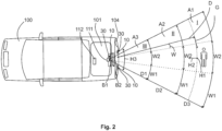
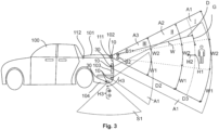
- FIGS. 2 and 3 show, in at least one, in several or in all operating modes I, II, III of the sensor device 10 of the sensor unit 12, different bandwidths W1, W2, for example a first bandwidth W1 or a second bandwidth W2, can be assigned.
- the respective bandwidth W1, W2 can determine the width of the respective activation area A1, A2, A3 in a simple manner.
- the activation areas A1, A2, A3 can be designed, for example, in the form of detection lobes. Different bandwidths W1, W2 can be advantageous for different functions. For example, a narrow activation area A1, A2, A3 can be advantageous for distance control for reversing parking. In another assistance system or for actuating the movable part 101, a wide activation area A1, A2, A3 can be advantageous in order to enable comprehensive monitoring of the activation area A1, A2, A3.
- the sensor unit 12 can detect a presence H1 and/or an approach H2 and/or a leg and/or foot movement H3 of the user as the at least one activation action H1, H2, H3, B1, B2 in the first activation area A1.
- the sensor unit 12 can be designed to detect at least a first movement pattern B1 or a second movement pattern B2 by a hand of the user as the at least one activation action H1, H2, H3, B1, B2 in the first activation area A1.
- the sensor device 10 can be used in combination with different technologies for actuating the movable part 101.
- control unit 11 can be designed to query the user's access authorization or can be in a communication connection ID with a security device 110 of the vehicle in order to verify the user's access authorization.
- control unit 11 can be designed to carry out or initiate a query of an access authorization of the user if a presence H1 and/or an approach H2 of the user has been detected as the at least one activation action H1, H2, H3, B1, B2 in the first activation area A1 with the aid of the sensor unit 12.
- control unit 11 can be awakened by the safety device 110 of the vehicle 100 in order to monitor the first activation area A1 for at least one activation action H1, H2, H3, B1, B2 with the aid of the sensor unit 12.
- the sensor unit 12 can monitor the first activation area A1 for a specific leg and/or foot movement H3 of the user and/or for a first movement pattern B1 and a second movement pattern B2 by a hand of the user. If the user has performed a suitable leg and/or foot movement H3 and/or a suitable first movement pattern B1 and a suitable second movement pattern B2, the tailgate 101 can be operated. For this purpose, the control unit 11 can send corresponding control signals to the locking device 111 and/or the drive device 112 of the tailgate 101.
- the leg and/or foot movement H3 of the user can be determined in the form of a movement with one leg of the user towards the movable part 101 and a kicking movement with one foot under the movable part 101 (see the arrows in the Figures 3 and 4 ).
- Another possible leg and/or foot movement H3 of the user can be determined in the form of a rocking movement with one foot under the movable part 101 (see the arrow in the Figure 2 ).
- control unit 11 can be designed to actuate the movable part 101 when a first movement pattern B1 and a second movement pattern B2 successively as the at least one activation action H1, H2, H3, B1, B2 were recorded in the first activation area A1 (see the arrow in the Figure 2 ).
- the first movement pattern B1 can be defined in the form of a stroking movement with one hand in a first direction along the movable part 101 and the second movement pattern B2 can be defined in the form of a stroking movement with one hand in a second direction along the movable part 101.
- the first direction and the second direction can be substantially horizontal and/or opposite (cf. the Figures 3 and 4 ).
- the sensor device 10 in the first operating mode I can be designed to stop an actuation of the movable part 101 if an obstacle that stands in the way of the actuation of the movable part 101 has been detected by means of the sensor unit 12.
- the movable part 101 can thus be operated safely.
- the sensor device 10 can be arranged on the movable part 101 itself, on an emblem 102, on a license plate 103, on a bumper 104 or on a diffuser of the vehicle 100.
- sensor devices 10 can be provided as part of an actuating device 30 for the movable component 101 in order to actuate the movable part.
- At least one sensor device 10 for monitoring at least a first activation region A1 can be provided in the region of the tailgate 101, for example on the tailgate itself, on an actuating device 30 for the tailgate 101 or on an emblem 104 of the vehicle 100.
- the first activation region A1 can have a substantially horizontal extension.
- a further or alternative sensor device 10 with a horizontal activation region A1 can be provided in the region of the license plate 103.
- a further or alternative sensor device 10 with a horizontal activation area A1 can be provided in the area of the bumper 104 or a diffuser of the vehicle 100.
- a further sensor device 10 can be provided in the area of the bumper 104 or a diffuser of the vehicle 100, which can be provided for monitoring a further switching range S1 of the movable part 101 of the vehicle 100, which can have a substantially vertical extension.
- the monitoring in the vertical switching range S1 of the movable part 101 of the vehicle 100 can advantageously serve to confirm that the user actually intends to operate the tailgate 101. To do this, the user can perform a kicking movement with the foot.
- the vertical switching range S1 can be used to detect a rocking movement with the foot under the movable part 101.
- one sensor device 10 may be sufficient to be able to recognize different activation actions H1, H2, H3, B1, B2 of the user.
- the invention can provide several alternative locations and/or combinations for one or more sensor devices 10 in order to expand the possible uses and the functionality of the actuating device 30.
- At least one further sensor unit 13 can be provided in order to detect the at least one activation action H1, H2, H3, B1, B2 of the user using electromagnetic waves in the optical frequency range or in the infrared range or using a capacitive measurement.
- a combination sensor system can thus be provided within the scope of a sensor device 10.
- the sensor device 10 with the control unit 11, the sensor unit 12, and possibly a further sensor unit 13, can be designed in the form of a modular unit in order to simplify the assembly of the sensor device 10.
- the sensor device 10 can have a carrier plate 3 for the control unit 11, the sensor unit 12, and possibly a further sensor unit 13. This allows for a simple assembly of the sensor device 10.
- the sensor unit 12 can have at least one or more, for example two or three, transceivers 2.
- Each transceiver 2 can have at least one, preferably two, transmitting antennas SA and at least one, preferably four, receiving antennas EA.
- SA transmitting antennas
- EA receiving antennas
- the control unit 11 can have at least one microcontroller 1.
- the microcontroller 1 further comprises at least one converter ADC, DAC, at least one signal processing unit SPT, at least one processor unit CPU, at least one memory unit RAM, at least one interface IF for further peripheral functions and/or at least one connection CAN for communication and/or power supply of the sensor device 10 with a voltage U, V.
- the microcontroller 1 can process and analyze the information of the sensor unit 12 in order to provide different operating modes of the sensor device 10.
- a housing 20 can be provided for the sensor device 10 in order to accommodate the sensor device 10 protected from environmental and/or weather influences.
- the housing 20 can completely enclose the sensor device 10.
- the sensor device 10 can thus be accommodated in a particularly protected and secure manner.
- the housing 20 for the sensor device 10 can have a cover element 21, which can advantageously be opened, through which the sensor device 10 can be introduced within the housing 20 and/or removed for repair purposes.
- the cover element 21 can be attached to the housing 20 in a removable, rotatable (for example using an articulated connection, for example in the form of a hinge) or displaceable (for example using a labyrinth guide).
- the cover element 21 can be used within the scope of the invention to close an opening in an outer skin of the movable part 101, a license plate 103, a bumper 104 or a diffuser of the vehicle 100. It is also conceivable that the cover element 21 can be arranged behind an outer skin of the movable part 101, a license plate 103, a bumper 104 or a diffuser of the vehicle 100. It is also conceivable that the cover element 21 for the housing 20 can be designed in the form of an emblem 102 of the vehicle 100.
- the housing 20 for the sensor device 10 and/or the cover element 21 can be made of a radar-transparent material, in particular plastic, preferably polymer, in order not to impair the functioning of the sensor unit 12.
- the housing 20 for the sensor device 10 and/or the cover element 21 and/or the outer skin of the respective movable component can be provided with a coating 22 at least in sections (cf. the Figures 6 and 7 ).
- the coating 22 can have a material thickness of 10 nm to 100 nm.
- the coating 22 can be in the form of a lacquer layer, a spray layer or a layer deposited by means of gas phase deposition or sputtering, for example.
- the coating 22 can also have metal particles, preferably chromium, and/or semiconductor material, preferably silicon, in order to obtain a metallic appearance.
- At least one or more mounting means 23 can be provided within the housing 20 for the sensor device 10 in order to receive the sensor device 10 in a form-fitting and/or force-fitting manner and to facilitate the assembly of the sensor device 10.
- the mounting means 23 are different locking and/or clamping and/or guiding means are conceivable, for example in the form of a circumferential groove 23 for the carrier plate 3 of the sensor device 10. The carrier plate 3 can simply be inserted into the groove 23.
- the housing 20 for the sensor device 10 can have at least one or more fastening means 24, for example in the form of latching and/or clamping and/or guiding means, which can interact with corresponding counter-latching means in order to fasten the sensor device 10 in a form-fitting and/or force-fitting manner to a vehicle-side opening (not shown) and/or to a vehicle-side support element (not shown).
- fastening means 24 for example in the form of latching and/or clamping and/or guiding means, which can interact with corresponding counter-latching means in order to fasten the sensor device 10 in a form-fitting and/or force-fitting manner to a vehicle-side opening (not shown) and/or to a vehicle-side support element (not shown).
Landscapes
- Engineering & Computer Science (AREA)
- Chemical & Material Sciences (AREA)
- Combustion & Propulsion (AREA)
- Transportation (AREA)
- Mechanical Engineering (AREA)
- Radar Systems Or Details Thereof (AREA)
- Lock And Its Accessories (AREA)
- Power-Operated Mechanisms For Wings (AREA)
Applications Claiming Priority (3)
| Application Number | Priority Date | Filing Date | Title |
|---|---|---|---|
| DE102018115581.6A DE102018115581A1 (de) | 2018-06-28 | 2018-06-28 | Sensorvorrichtung für ein Fahrzeug |
| EP19732580.6A EP3814596A1 (fr) | 2018-06-28 | 2019-06-18 | Dispositif de détection pour un véhicule |
| PCT/EP2019/065924 WO2020002033A1 (fr) | 2018-06-28 | 2019-06-18 | Dispositif de détection pour un véhicule |
Related Parent Applications (1)
| Application Number | Title | Priority Date | Filing Date |
|---|---|---|---|
| EP19732580.6A Division EP3814596A1 (fr) | 2018-06-28 | 2019-06-18 | Dispositif de détection pour un véhicule |
Publications (2)
| Publication Number | Publication Date |
|---|---|
| EP4459092A2 true EP4459092A2 (fr) | 2024-11-06 |
| EP4459092A3 EP4459092A3 (fr) | 2025-01-15 |
Family
ID=67001767
Family Applications (2)
| Application Number | Title | Priority Date | Filing Date |
|---|---|---|---|
| EP24195156.5A Pending EP4459092A3 (fr) | 2018-06-28 | 2019-06-18 | Dispositif de détection pour un véhicule |
| EP19732580.6A Pending EP3814596A1 (fr) | 2018-06-28 | 2019-06-18 | Dispositif de détection pour un véhicule |
Family Applications After (1)
| Application Number | Title | Priority Date | Filing Date |
|---|---|---|---|
| EP19732580.6A Pending EP3814596A1 (fr) | 2018-06-28 | 2019-06-18 | Dispositif de détection pour un véhicule |
Country Status (5)
| Country | Link |
|---|---|
| US (1) | US11920400B2 (fr) |
| EP (2) | EP4459092A3 (fr) |
| CN (1) | CN112272727A (fr) |
| DE (1) | DE102018115581A1 (fr) |
| WO (1) | WO2020002033A1 (fr) |
Families Citing this family (22)
| Publication number | Priority date | Publication date | Assignee | Title |
|---|---|---|---|---|
| CN110023580B (zh) * | 2016-11-30 | 2022-03-22 | 株式会社有信 | 车辆门开闭装置 |
| DE102019003008A1 (de) * | 2019-04-26 | 2020-10-29 | Daimler Ag | Verfahren zum Betreiben eines Fahrerassistenzsystems eines zumindest teilweise elektrisch betreibbaren Kraftfahrzeugs zum Ansteuern von vier Rädern, Fahrerassistenzsystem sowie Kraftfahrzeug |
| US11701954B2 (en) * | 2020-05-14 | 2023-07-18 | Extang Corporation | Integrated vehicle cover |
| EP3968290B1 (fr) | 2020-09-10 | 2024-03-27 | ADAC Plastics, Inc. | Système d'accès par gestes pour véhicule à moteur |
| CN112709513B (zh) * | 2020-12-30 | 2022-04-08 | 奇瑞汽车股份有限公司 | 一种基于轮询钥匙定位实现汽车尾门自动控制的系统和方法 |
| DE102021203384B3 (de) * | 2021-04-06 | 2022-06-23 | Vitesco Technologies GmbH | Fahrzeug mit Sensoreinheit zur berührungslosen Betätigung eines Fahrzeugelements |
| CN113250578B (zh) * | 2021-06-16 | 2022-12-09 | 上汽通用汽车有限公司 | 一种车门控制方法、系统、装置及存储介质 |
| US20230017327A1 (en) * | 2021-07-14 | 2023-01-19 | Ford Global Technologies, Llc | Tailgate Position Management Systems And Methods |
| CA3225700A1 (fr) | 2021-07-15 | 2023-01-19 | Mark B. Barron | Systeme de protection de securite de vehicule a reglage de hauteur |
| EP4387873A4 (fr) | 2021-08-18 | 2025-05-21 | Public Transportation Safety Int'l Corp. | Protection de sécurité déployable automatiquement de véhicule |
| DE102021209108A1 (de) * | 2021-08-19 | 2023-02-23 | Vitesco Technologies GmbH | Vorrichtung und Verfahren zum Schließen einer Fahrzeugklappe eines Fahrzeugs |
| US12282113B2 (en) * | 2021-08-25 | 2025-04-22 | Kokusai Denki Electric Inc. | Radar system, radar device, and monitoring method |
| DE102021122903A1 (de) * | 2021-09-03 | 2023-03-09 | Brose Fahrzeugteile Se & Co. Kommanditgesellschaft, Bamberg | Verfahren zum Betrieb einer motorischen Klappenanordnung |
| DE102021122890A1 (de) * | 2021-09-03 | 2023-03-09 | Brose Fahrzeugteile Se & Co. Kommanditgesellschaft, Bamberg | Verfahren für den Betrieb einer Klappenanordnung eines Kraftfahrzeugs |
| US11738810B2 (en) * | 2021-10-29 | 2023-08-29 | AISIN Technical Center of America, Inc. | Power tailgate cargo load sensor |
| KR20230075970A (ko) * | 2021-11-23 | 2023-05-31 | 현대자동차주식회사 | 트렁크 이용 편의를 위한 차량 제어방법 및 장치 |
| US12235387B2 (en) * | 2022-03-11 | 2025-02-25 | International Truck Intellectual Property Company, Llc | Sensor shield and method |
| DE102022118777B4 (de) * | 2022-07-27 | 2025-05-08 | Dr. Ing. H.C. F. Porsche Aktiengesellschaft | Fahrzeug, Vorrichtung und Verfahren zum sensorbasierten Konfigurieren einer Annäherungserkennung für das Fahrzeug |
| DE102023117003A1 (de) * | 2023-01-22 | 2024-07-25 | Huf Hülsbeck & Fürst Gmbh & Co. Kg | Feststehende Betätigungsvorrichtung für ein Fahrzeug |
| DE102023119248A1 (de) * | 2023-07-20 | 2025-01-23 | Huf Hülsbeck & Fürst Gmbh & Co. Kg | Betätigungsvorrichtung und Verfahren für ein Zugangssystem eines Fahrzeuges |
| DE102023004100A1 (de) * | 2023-10-12 | 2024-06-27 | Mercedes-Benz Group AG | Türgriff sowie Kraftfahrzeug |
| DE102024209819A1 (de) * | 2024-10-09 | 2026-04-09 | Schaeffler Technologies AG & Co. KG | Vorrichtung zum Erkennen einer vorbestimmten Geste zum Auslösen eines Öffnungs- oder Schließvorgangs einer Fahrzeugklappe und Fahrzeugklappe |
Family Cites Families (12)
| Publication number | Priority date | Publication date | Assignee | Title |
|---|---|---|---|---|
| DE102012107284A1 (de) * | 2012-08-08 | 2014-02-13 | Brose Fahrzeugteile Gmbh & Co. Kommanditgesellschaft, Hallstadt | Steuerungsverfahren und Steuerungssystem für ein Fahrzeugschließelement |
| KR101428240B1 (ko) | 2012-12-04 | 2014-08-07 | 현대자동차주식회사 | 핸즈프리 파워 테일게이트 시스템 및 그 제어 방법 |
| DE102014101661A1 (de) | 2014-02-11 | 2015-08-13 | Brose Fahrzeugteile Gmbh & Co. Kommanditgesellschaft, Hallstadt | Verfahren zur Ansteuerung einer Verschlusselementanordnung eines Kraftfahrzeugs |
| CN104536006B (zh) * | 2014-09-09 | 2017-08-25 | 珠海上富电技股份有限公司 | 倒车雷达和后尾箱开启功能结合的系统及其控制方法 |
| US9580046B2 (en) | 2014-12-11 | 2017-02-28 | Ford Global Technologies, Llc | Entry assist system for a motor vehicle |
| CN204575849U (zh) * | 2015-05-11 | 2015-08-19 | 上海量度电子科技有限公司 | 一种多用途汽车雷达 |
| CN205010119U (zh) | 2015-08-31 | 2016-02-03 | 珠海上富电技股份有限公司 | 泊车、盲区及后备箱开启三合一的检测系统 |
| CN105365695B (zh) * | 2015-08-31 | 2018-03-02 | 珠海上富电技股份有限公司 | 泊车、盲区及后备箱开启三合一的检测系统及检测方法 |
| DE102015011930A1 (de) * | 2015-09-12 | 2017-03-16 | Audi Ag | Verfahren zum Betrieb eines Fahrerassistenzsystems zur Unterstützung von wenigstens einer Person außerhalb eines Kraftfahrzeugs |
| DE102016210364A1 (de) * | 2016-06-10 | 2017-12-14 | Audi Ag | Verfahren zur Steuerung einer Verschlusseinrichtung eines Kraftfahrzeugs und Kraftfahrzeug |
| DE102017215650A1 (de) | 2016-09-08 | 2018-03-08 | Magna Closures Inc. | Benutzeranzeige der Aktivierung eines angetriebenen Systems während berührungsloser menschlicher Aktivierung |
| US20180094471A1 (en) | 2016-10-03 | 2018-04-05 | Magna Mirrors Of America, Inc. | Vehicle window with gesture control |
-
2018
- 2018-06-28 DE DE102018115581.6A patent/DE102018115581A1/de active Pending
-
2019
- 2019-06-18 WO PCT/EP2019/065924 patent/WO2020002033A1/fr not_active Ceased
- 2019-06-18 CN CN201980038801.8A patent/CN112272727A/zh active Pending
- 2019-06-18 EP EP24195156.5A patent/EP4459092A3/fr active Pending
- 2019-06-18 EP EP19732580.6A patent/EP3814596A1/fr active Pending
- 2019-06-18 US US17/254,575 patent/US11920400B2/en active Active
Also Published As
| Publication number | Publication date |
|---|---|
| WO2020002033A1 (fr) | 2020-01-02 |
| US20210246708A1 (en) | 2021-08-12 |
| US11920400B2 (en) | 2024-03-05 |
| CN112272727A (zh) | 2021-01-26 |
| DE102018115581A1 (de) | 2020-01-02 |
| EP3814596A1 (fr) | 2021-05-05 |
| EP4459092A3 (fr) | 2025-01-15 |
Similar Documents
| Publication | Publication Date | Title |
|---|---|---|
| EP4459092A2 (fr) | Dispositif de détection pour un véhicule | |
| EP1902912B1 (fr) | Véhicule automobile doté d'un dispositif de détection | |
| EP3599136B1 (fr) | Dispositif de détection pour un véhicule | |
| DE102018127038A1 (de) | Radarbasiertes Multifunktions-Detektorsystem für eine Fahrzeug-Hubtür | |
| DE102019130857A1 (de) | Berührungsloses seitentür-hinderniserkennungssystem und -verfahren | |
| EP1733937B1 (fr) | Procédé d'ouverture automatique pour un ouvrant d'un véhicule | |
| DE10361115A1 (de) | Verfahren zur Fernbedienung von Türen und/oder Klappen für Fahrzeuge und zugehöriges Fernbediensystem | |
| DE102018202343A1 (de) | Kraft-schwenktür mit virtual-handgriff -gestensteuerung | |
| WO2014102178A1 (fr) | Dispositif de fermeture pour un véhicule et procédé pour faire fonctionner un dispositif de fermeture | |
| DE102008041354A1 (de) | Verfahren und Vorrichtung zum automatischen Öffnen einer Fahrzeugtüre oder dergleichen | |
| DE102013010993A1 (de) | Objekterfassungsvorrichtung für ein Fahrzeug | |
| EP3984837B1 (fr) | Système d'actionnement uwb pour une partie mobile d'un véhicule | |
| EP2159362A1 (fr) | Véhicule avec dispositif d'ouverture automatique d'un volet de véhicule | |
| DE102004055982A1 (de) | Schließsystem für ein Fahrzeug | |
| DE102020114403A1 (de) | Zugangskontrollsystem und Verfahren zum Steuern einer Zugangskontrolle | |
| WO2016180582A1 (fr) | Actionnement d'un élément de fermeture d'un véhicule au moyen d'un capteur ultrasonore | |
| DE102014001321B4 (de) | Verfahren zum Betrieb mindestens eines Bedienelements für eine Fahrzeugtür eines Kraftfahrzeugs und Kraftfahrzeug | |
| DE102020209357A1 (de) | Fahrzeug mit Zierelement | |
| DE102018207663B3 (de) | Verfahren zum Erfassen einer Nutzereingabe und Fahrzeug | |
| WO2024153416A1 (fr) | Dispositif d'actionnement mobile pour un véhicule | |
| WO2025067704A1 (fr) | Dispositif d'actionnement et procédé d'actionnement d'une partie mobile d'un véhicule | |
| WO2025016849A1 (fr) | Dispositif d'actionnement et procédé pour un système d'accès d'un véhicule | |
| DE102023119245A1 (de) | Betätigungsvorrichtung und Verfahren zum Betätigen eines beweglichen Teils eines Fahrzeuges | |
| DE102022118048A1 (de) | Verfahren und Vorrichtung zum Erfassen einer Aktivierungshandlung eines Benutzers mithilfe von Radarwellen | |
| DE102023101489A1 (de) | Bewegliche Betätigungsvorrichtung für ein Fahrzeug |
Legal Events
| Date | Code | Title | Description |
|---|---|---|---|
| PUAI | Public reference made under article 153(3) epc to a published international application that has entered the european phase |
Free format text: ORIGINAL CODE: 0009012 |
|
| STAA | Information on the status of an ep patent application or granted ep patent |
Free format text: STATUS: THE APPLICATION HAS BEEN PUBLISHED |
|
| AC | Divisional application: reference to earlier application |
Ref document number: 3814596 Country of ref document: EP Kind code of ref document: P |
|
| AK | Designated contracting states |
Kind code of ref document: A2 Designated state(s): AL AT BE BG CH CY CZ DE DK EE ES FI FR GB GR HR HU IE IS IT LI LT LU LV MC MK MT NL NO PL PT RO RS SE SI SK SM TR |
|
| PUAL | Search report despatched |
Free format text: ORIGINAL CODE: 0009013 |
|
| AK | Designated contracting states |
Kind code of ref document: A3 Designated state(s): AL AT BE BG CH CY CZ DE DK EE ES FI FR GB GR HR HU IE IS IT LI LT LU LV MC MK MT NL NO PL PT RO RS SE SI SK SM TR |
|
| RIC1 | Information provided on ipc code assigned before grant |
Ipc: E05F 15/73 20150101AFI20241210BHEP |
|
| STAA | Information on the status of an ep patent application or granted ep patent |
Free format text: STATUS: REQUEST FOR EXAMINATION WAS MADE |
|
| 17P | Request for examination filed |
Effective date: 20250715 |
|
| STAA | Information on the status of an ep patent application or granted ep patent |
Free format text: STATUS: EXAMINATION IS IN PROGRESS |
|
| 17Q | First examination report despatched |
Effective date: 20260224 |