EP4459096A2 - Détermination de la résistance à la compression non confinée à partir de données de forage et de paramètres de trépan - Google Patents
Détermination de la résistance à la compression non confinée à partir de données de forage et de paramètres de trépan Download PDFInfo
- Publication number
- EP4459096A2 EP4459096A2 EP24173893.9A EP24173893A EP4459096A2 EP 4459096 A2 EP4459096 A2 EP 4459096A2 EP 24173893 A EP24173893 A EP 24173893A EP 4459096 A2 EP4459096 A2 EP 4459096A2
- Authority
- EP
- European Patent Office
- Prior art keywords
- drilling
- drill bit
- wellbore
- hypothetical
- doc
- Prior art date
- Legal status (The legal status is an assumption and is not a legal conclusion. Google has not performed a legal analysis and makes no representation as to the accuracy of the status listed.)
- Pending
Links
Images


Classifications
-
- E—FIXED CONSTRUCTIONS
- E21—EARTH OR ROCK DRILLING; MINING
- E21B—EARTH OR ROCK DRILLING; OBTAINING OIL, GAS, WATER, SOLUBLE OR MELTABLE MATERIALS OR A SLURRY OF MINERALS FROM WELLS
- E21B44/00—Automatic control systems specially adapted for drilling operations, i.e. self-operating systems which function to carry out or modify a drilling operation without intervention of a human operator, e.g. computer-controlled drilling systems; Systems specially adapted for monitoring a plurality of drilling variables or conditions
-
- E—FIXED CONSTRUCTIONS
- E21—EARTH OR ROCK DRILLING; MINING
- E21B—EARTH OR ROCK DRILLING; OBTAINING OIL, GAS, WATER, SOLUBLE OR MELTABLE MATERIALS OR A SLURRY OF MINERALS FROM WELLS
- E21B10/00—Drill bits
- E21B10/46—Drill bits characterised by wear resisting parts, e.g. diamond inserts
- E21B10/56—Button-type inserts
- E21B10/567—Button-type inserts with preformed cutting elements mounted on a distinct support, e.g. polycrystalline inserts
-
- E—FIXED CONSTRUCTIONS
- E21—EARTH OR ROCK DRILLING; MINING
- E21B—EARTH OR ROCK DRILLING; OBTAINING OIL, GAS, WATER, SOLUBLE OR MELTABLE MATERIALS OR A SLURRY OF MINERALS FROM WELLS
- E21B43/00—Methods or apparatus for obtaining oil, gas, water, soluble or meltable materials or a slurry of minerals from wells
- E21B43/25—Methods for stimulating production
- E21B43/26—Methods for stimulating production by forming crevices or fractures
-
- E—FIXED CONSTRUCTIONS
- E21—EARTH OR ROCK DRILLING; MINING
- E21B—EARTH OR ROCK DRILLING; OBTAINING OIL, GAS, WATER, SOLUBLE OR MELTABLE MATERIALS OR A SLURRY OF MINERALS FROM WELLS
- E21B49/00—Testing the nature of borehole walls; Formation testing; Methods or apparatus for obtaining samples of soil or well fluids, specially adapted to earth drilling or wells
-
- E—FIXED CONSTRUCTIONS
- E21—EARTH OR ROCK DRILLING; MINING
- E21B—EARTH OR ROCK DRILLING; OBTAINING OIL, GAS, WATER, SOLUBLE OR MELTABLE MATERIALS OR A SLURRY OF MINERALS FROM WELLS
- E21B49/00—Testing the nature of borehole walls; Formation testing; Methods or apparatus for obtaining samples of soil or well fluids, specially adapted to earth drilling or wells
- E21B49/003—Testing the nature of borehole walls; Formation testing; Methods or apparatus for obtaining samples of soil or well fluids, specially adapted to earth drilling or wells by analysing drilling variables or conditions
-
- E—FIXED CONSTRUCTIONS
- E21—EARTH OR ROCK DRILLING; MINING
- E21B—EARTH OR ROCK DRILLING; OBTAINING OIL, GAS, WATER, SOLUBLE OR MELTABLE MATERIALS OR A SLURRY OF MINERALS FROM WELLS
- E21B7/00—Special methods or apparatus for drilling
- E21B7/04—Directional drilling
- E21B7/06—Deflecting the direction of boreholes
- E21B7/068—Deflecting the direction of boreholes drilled by a down-hole drilling motor
-
- E—FIXED CONSTRUCTIONS
- E21—EARTH OR ROCK DRILLING; MINING
- E21B—EARTH OR ROCK DRILLING; OBTAINING OIL, GAS, WATER, SOLUBLE OR MELTABLE MATERIALS OR A SLURRY OF MINERALS FROM WELLS
- E21B2200/00—Special features related to earth drilling for obtaining oil, gas or water
- E21B2200/20—Computer models or simulations, e.g. for reservoirs under production, drill bits
Definitions
- the present disclosure generally relates to determination of unconfined (aka uniaxial) compressive strength (UCS) from drilling data and drill bit parameters.
- UCS unconfined compressive strength
- US 4,914,591 discloses a method for determining rock compressive strength of a subterranean formation penetrated by a wellbore.
- a mathematical model of a drill bit and an estimate of rock ductility of a particular subterranean formation in conjunction with weight-on-bit (WOB), bit rotational speed RPM, and rate of penetration (ROP) are used as inputs. From the above inputs, the rock compressive strength can be determined while the wellbore is being drilled or afterwards.
- a depth correlated log can be generated of rock compressive strength that can be compared to other logs obtained from adjacent wellbores to obtain a refined estimate of the depth of a particular subterranean formation feature.
- the above method can be utilized for obtaining an indication of bit wear or bit damage while the bit is drilling a wellbore by comparing a first rock compressive strength log of a wellbore to a rock compressive strength log being generated while the drill bit is actually drilling a second wellbore. Any significant deviation between the two logs provides an indication of bit wear or bit damage.
- US 7,555,414 discloses a method for estimating the CCS for a rock in the depth of cut zone of a subterranean formation which is to be drilled using a drilling fluid is disclosed.
- An UCS is determined for a rock in the depth of cut zone.
- a change in the strength of the rock due to applied stresses imposed on the rock during drilling is calculated which includes estimating the ⁇ PP.
- the CCS for the rock in the depth of cut zone is calculated by adding the estimated change in strength to the UCS.
- the present invention calculates the ⁇ PP in accordance with Skempton theory where impermeable rock or soil has a change in pore volume due to applied loads or stresses while fluid flow into and out of the rock or soil is substantially non-existent.
- CCS may be calculated for deviated wellbores and to account for factors such as wellbore profile, stress raisers, bore diameter, and mud weight utilizing correction factors derived using computer modeling and using a baseline formula for determining an uncorrected value for CCS.
- US 8,082,104 discloses a method of identifying one or more rock properties and/or one or more abnormalities occurring within a subterranean formation.
- the method includes obtaining a plurality of drilling parameters, which include at least the rate of penetration, the weight on bit, and the bit revolutions per minute, and then normalizing these plurality of drilling parameters by calculating a depth of cut and an intrinsic drilling impedance.
- the intrinsic drilling impedance is specific to the type of bit used to drill the wellbore and includes using a plurality of drill bit constants. From this intrinsic drilling impedance, the porosity and/or the rock strength may be determined which is then compared to the actual values to identify the specific type of the one or more abnormalities occurring. Additionally, the intrinsic drilling impedance may be compared to other logging parameters to also identify the specific type of the one or more abnormalities occurring.
- US 9,556,728 discloses a method for analyzing a wellbore drilling operation includes acquiring sonic log data, gamma ray log data, and rate of penetration (ROP) data.
- the sonic log data, the gamma ray log data, and the ROP data are associated with depth intervals of a wellbore.
- the method further includes determining unconfined compressive strength (UCS) of a rock formation associated with the wellbore using well log data and drilling data.
- UCS unconfined compressive strength
- the well log data is limited to the sonic log data and the gamma ray log data
- the drilling data is limited to the ROP data.
- US 10,094,210 discloses estimation of rock strength during drilling using a rate of penetration model or a modified mechanical specific energy model.
- the rock strength estimate can be used in conducting further drilling, for example by a drilling system.
- Drilling parameters may be altered as a result of determining rock strength, for example to avoid undesirable trending fractures, such as extensive vertical fractures.
- US 10,963,600 discloses estimating in-situ stress of an interval having drilling response data is described. Estimating involves obtaining drilling response data of a data rich interval with available data. Estimating relative rock strength as a composite value that includes in-situ stress and rock strength. Estimating a Poisson's ratio from the relative rock strength. Generating a stress model that includes uniaxial strain model using the Poisson's ratio. Verifying the stress model with the available data. Applying the stress models in a non-data rich interval.
- US 11,905,828 discloses a method and a system for a confined compressive strength (CCS) and an unconfined compressive strength (UCS) for one or more bedding layers.
- the method may include identifying a depth interval during a drilling operation as a distance between a first depth and a second depth, measuring one or more drill bit responses within the depth interval using a sensor package disposed on the drill bit, identifying one or more torsional bit vibrations, and identifying one or more bedding layers of the formation within the depth interval from the one or more torsional bit vibrations.
- the method may further include identifying the (CCS) and the (UCS) for each of the one or more bedding layers and identifying a bit wear of the drill bit within each of the one or more bedding layers using the one or more drill bit responses and the one or more torsional bit vibrations.
- the paper SPWLA-2022-0039 discloses that proper understanding of the strength of rocks, and its variability along the length of the well, is essential for efficient and economic drilling operation.
- the industry has used log-based strength estimates calibrated to strength measured on core samples.
- coring and core testing is costly and time consuming and downhole logs may also be left out of the program to manage costs.
- drilling data is almost always available as the well is drilled.
- An innovative and robust method is presented which capitalizes on availability of drilling tools, which measure key drilling data downhole. As the measurements are acquired downhole, uncertainties associated with surface-to-downhole conversions are reduced. Reliable results are available over the length of the wellbore, irrespective of complexity in well trajectory.
- the work also reviews the development of tools measuring downhole-drilling data.
- This method uses downhole weight-on-bit, rotational speed, downhole torque, and rate-of-penetration to characterize the downhole mechanical specific energy (MSEDownhole) consumed in the process.
- MSEDownhole downhole mechanical specific energy
- the bit diameter, mud-weight, and depth of drilling are also accounted for. If the task is to optimize drilling parameters for a new formation (e.g. drill-off-test), then the parameters with the "minimum” MSEDownhole are captured. However, if the task is for stage and cluster-wise hydraulic fracture design, then "instantaneous" MSEDownhole is used to infer confined compressive strength (CCS).
- CCS confined compressive strength
- the CCS together with internal friction angle (IFA) provides unconfined compressive strength (UCS) using Mohr-failure envelope inversion.
- the MSEDownhole is compared to Drilling Strength over the same interval.
- Drilling Strength is defined as Weight on Bit / (Bit Diameter * Penetration per Revolution) and has been used to estimate rock strength.
- the comparison between MSEDownhole and Drilling Strength highlights the differences in the estimated strength from the two methods.
- Current work shows the results from 14 drilling simulator tests, in shale and limestone, under typical ⁇ drill-off-test.' The minimum-MSE obtained was transformed to CCS using user-defined ⁇ efficiency factor.' The CCS was translated to UCS using basic Mohr-failure envelope and compared with core test data.
- rock strength logs are used to conduct different types of analysis such as preventing wellbore failure, deciding on completion design methods and controlling sand production.
- One source of data which is often overlooked in calculating rock strength is drilling data.
- To utilize the drilling data in calculating strength correlations are developed from inverted rate of penetration models. From these models unconfined compressive rock strength can be calculated from drilling data.
- the rate of penetration models takes into account operational drilling parameters, bit types/designs and geological formation information. Results from various onshore and offshore fields verify that drilling based rock strength compares to other methods of estimating rock strength.
- the big advantage using drilling data is that rock strength can be calculated for all hole sections, less expensive onshore wells and from old wells, where electrical logs or preserved core samples do not exist.
- the paper titled " Relationship between rock uniaxial compressive strength and digital core drilling parameters and its forecast method" by Hongke Gao et. Al, from: Int J Coal Sci Technol (2021) 8(4):605-613 discloses that the rock uniaxial compressive strength (UCS) is the basic parameter for support designs in underground engineering.
- the rock UCS should be obtained rapidly for underground engineering with complex geological conditions, such as soft rock, fracture areas, and high stress, to adjust the excavation and support plan and ensure construction safety.
- a rock UCS forecast idea is proposed using digital core drilling. The digital core drilling tests and uniaxial compression tests are performed based on the developed rock mass digital drilling system.
- the results indicate that the drilling parameters are highly responsive to the rock UCS.
- the mechanical analysis of rock cutting provides the digital core drilling strength, and a quantitative relationship model (CDP-UCS model) for the digital core drilling parameters and rock UCS is established.
- CDP-UCS model quantitative relationship model
- the digital core drilling-based rock UCS forecast method is proposed to provide a theoretical basis for continuous and quick testing of the surrounding rock UCS.
- a method for monitoring a drilling operation includes: providing a drill bit for drilling a wellbore into a geological formation using a drilling motor for rotating the drill bit; determining depth of cut (DOC) of the drill bit and torque exerted on the drill bit by the drilling motor using parameters measured while drilling the wellbore; simulating drilling of a hypothetical wellbore using a hypothetical drill bit similar or identical to the drill bit and determining a function that provides strength of a hypothetical geological formation from the DOC of the hypothetical drill bit and the torque exerted on the hypothetical drill bit; and determining strength of the geological formation using the function and the determined DOC and the torque.
- DOC depth of cut
- a method for monitoring a drilling operation includes: providing a drill bit for drilling a wellbore into a geological formation using a drilling motor for rotating the drill bit; determining depth of cut (DOC) of the drill bit and torque exerted on the drill bit by the drilling motor using parameters measured while drilling the wellbore; simulating drilling of a hypothetical wellbore using a hypothetical drill bit similar or identical to the drill bit and determining a function that provides weight on bit (WOB) of the simulated drilling from the DOC of the hypothetical drill bit and the torque exerted on the hypothetical drill bit; and determining WOB using the function and the determined DOC and the torque.
- DOC depth of cut
- WOB weight on bit
- FIG. 1 illustrates drilling of a first wellbore 1a into a geological formation 17, according to one embodiment of the present disclosure.
- the first wellbore 1a may be drilled using a drilling system 2.
- the drilling system 2 may include a drilling rig 2r, a fluid handling system 2f, a blowout preventer (BOP) 2b, a drill string 3, and a controller, such as programmable logic controller (PLC) 2p.
- the drilling rig 2r may include a derrick 4d, top drive 5, draw works 6, and a floor 4f at its lower end having an opening through which the drill string 3 extends downwardly into the first wellbore 1a via a wellhead 19h.
- the BOP 2b may be connected to the wellhead 19h.
- FIG 2A illustrates a bottom hole assembly (BHA) 3b used in drilling of the first wellbore 1a.
- the drill string 3 may include the BHA 3b and a pipe string 3p.
- the pipe string 3p may include joints of drill pipe connected together, such as by threaded couplings.
- the BHA 3b may be connected to the pipe string 3p, such as by threaded couplings, and include a drill bit 7, a measurement while drilling (MWD) sub 8w, a bent sub 8b, and a drilling motor 8m.
- the drilling motor 8m may be a mud motor.
- the BHA members 7, 8b,m,w may be interconnected, such as by threaded couplings.
- the MWD sub 8w may include one or more sensors, such as accelerometers and magnetometers, to enable the PLC 2p to calculate navigation parameters, such as azimuth, inclination, and/or tool face angle of the BHA 3b.
- the MWD sub 8w may be connected to the bent sub 8b and the pipe string 3p.
- the bent sub 3b may be connected to the MWD sub 8w and a stator of the drilling motor 8m.
- the drill bit 7 may be connected to a rotor of the drilling motor 8m.
- the drill bit 7 may include the cutting face, a bit body, a shank, and a gage section.
- a lower portion of the bit body may be made from a composite material, such as a ceramic and/or cermet matrix powder infiltrated by a metallic binder, and an upper portion of the bit body may be made from a softer material than the composite material of the upper portion, such as a metal or alloy shoulder powder infiltrated by the metallic binder.
- the bit body may be mounted to the shank during molding thereof.
- the shank may be tubular and made from a metal or alloy, such as steel, and have a coupling, such as a threaded pin, formed at an upper end thereof for connection of the drill bit 1a to drilling motor 8m.
- the shank may have a flow bore formed therethrough and the flow bore may extend into the bit body to a plenum (not shown) thereof.
- the cutting face may form a lower end of the drill bit 7 and the gage section may form at an outer portion thereof.
- the bit body 2 may be metallic, such as being made from steel, and may be hardfaced.
- the metallic bit body may be connected to a modified shank by threaded couplings and then secured by a weld or the metallic bit body may be monoblock having an integral body and shank.
- the cutting face may include one or more primary blades, one or more secondary blades, fluid courses formed between the blades, a row of leading cutters mounted along each blade, and backup cutters mounted to each blade.
- the cutting face may have one or more sections, such as an inner cone, an outer shoulder, and an intermediate nose between the cone and the shoulder sections.
- the blades may be disposed around the cutting face and each blade may be formed during molding of the bit body and may protrude from a bottom of the bit body.
- the primary blades and the secondary blades may be arranged about the cutting face in an alternating fashion.
- the primary blades may each extend from a center of the cutting face, across a portion of the cone section, across the nose and shoulder sections, and to the gage section.
- the secondary blades may each extend from a periphery of the cone section, across the nose and shoulder sections, and to the gage section. Each blade may extend generally radially across the portion of the cone section (primary only) and nose section with a slight spiral curvature and across the shoulder section radially and longitudinally with a slight helical curvature. Each primary blade may be inclined in the cone section by a cone angle. The cone angle may range between five and forty-five degrees.
- Each blade may be made from the same material as the lower portion of the bit body.
- the leading cutters may be mounted along leading edges of the blades after infiltration of the bit body.
- the leading cutters may be pre-formed, such as by high pressure and temperature sintering, and mounted, such as by brazing, in respective leading pockets formed in the blades adjacent to the leading edges thereof.
- Each blade may have a lower face extending between a leading edge and a trailing edge thereof. Starting in the nose section or shoulder section, each blade may have a row of backup pockets formed in the lower face thereof and extending therealong. Each backup pocket may be aligned with or slightly offset from a respective leading pocket.
- the backup cutters may be mounted, such as by brazing, in the backup pockets formed in the lower faces of the blades.
- the backup cutters may be pre-formed, such as by high pressure and temperature sintering.
- the backup cutters may extend along at least the shoulder section of each blade.
- the drill bit 7 may further include shock studs protruding from the lower face of each primary blade in the cone section and each shock stud may be aligned with or slightly offset from a respective leading cutter.
- One or more ports may be formed in the bit body and each port may extend from the plenum and through the bottom of the bit body to discharge the drilling fluid 21 along the fluid courses.
- a nozzle may be disposed in each port and fastened to the bit body. Each nozzle may be fastened to the bit body by having a threaded coupling formed in an outer surface thereof and each port may be a threaded socket for engagement with the respective threaded coupling.
- the ports may include an inner set of one or more ports disposed in the cone section and an outer set of one or more ports disposed in the nose section and/or shoulder section. Each inner port may be disposed between an inner end of a respective secondary blade and the center of the cutting face.
- the gage section may define a gage diameter of the drill bit.
- the gage section may include a plurality of gage pads (not shown), such as one gage pad for each blade, a plurality of gage trimmers and junk slots formed between the gage pads.
- the junk slots may be in fluid communication with the fluid courses formed between the blades.
- the gage pads may be disposed around the gage section and each pad may be formed during molding of the bit body and may protrude from the outer portion of the bit body.
- Each gage pad may be made from the same material as the bit body and each gage pad may be formed integrally with a respective blade.
- Each gage pad may extend upward from a shoulder portion of the respective blade to an exposed outer surface of the shank.
- Each gage pad may have a rectangular lower portion and a tapered upper portion.
- the tapered upper portions may transition an outer diameter of the drill bit 7 from the gage diameter to a lesser diameter of the shank.
- a taper angle may be the same for each upper portion and may range between thirty and sixty degrees as measured from a transverse axis of the drill bit.
- Each gage trimmer may be mounted to a leading edge of each lower portion.
- the gage trimmers may be mounted, such as by brazing, in respective pockets formed in the lower portions adjacent to the leading edges thereof.
- the rectangular lower portions may have flat outer surfaces (except for the pockets therein).
- the gage trimmers may have flats formed in outer surfaces thereof so as not to extend past the gage diameter of the drill bit.
- gage pads may have gage protectors embedded therein.
- Each cutter and gage trimmer may include a superhard cutting table, such as polycrystalline diamond (PCD), attached to a hard substrate, such as a cermet, thereby forming a compact, such as a polycrystalline diamond compact (PDC).
- PCD polycrystalline diamond
- Each cutter gage trimmer may be a shear cutter having a planar working face.
- the cermet may be a carbide cemented by a Group VIIIB metal, such as cobalt.
- the substrate and the cutting table may each be solid and cylindrical and a diameter of the substrate may be equal to a diameter of the cutting table.
- a working face of each cutter and gage trimmer may be opposite to the substrate and may be smooth and planar.
- Each gage protector may be made from thermally stable PCD or PDC.
- one or more of the cutters of each blade may have a non-planar working face.
- the drill bit 7 may be rotated 9r by the top drive 5 via the pipe string 3p and/or by the drilling motor 8m.
- the BHA 3b may be operable in a rotary mode or a sliding mode.
- the pipe string 3p may be held rotationally stationary and inclination of the drill bit 7 by the bent sub 3b may cause drilling along a curved trajectory.
- the drill string 3 may be rotated 9r by the top drive 5 to negate the curvature effect of the bent sub 8b (aka corkscrew path) and the drilling trajectory may be straight.
- the inclination of the bent sub 3b has been exaggerated for illustrative purpose.
- the BHA 3b may further include a transmitter for communication of the MWD sub 8w with the PLC 2p (and the PLC may include a corresponding receiver).
- the bent sub 8b may be integrated with the drilling motor 8m.
- the bent sub 8b and/or the MWD sub 8w may be omitted from the BHA 3b.
- an upper end of the pipe string 3p may be connected to a quill of the top drive 5.
- the top drive 5 may include a motor for rotating 9r the drill string 3.
- the top drive motor may be electric or hydraulic.
- a frame of the top drive 5 may be coupled to a rail (not shown) of the derrick 4d for preventing rotation of the top drive frame during rotation 9r of the drill string 3 and allowing for vertical movement of the top drive with a traveling block 6t of the draw works 6.
- the frame of the top drive 5 may be suspended from the derrick 4d by the traveling block 6t.
- the traveling block 6t may be supported by wire rope 6r connected at its upper end to a crown block 6c.
- the wire rope 6r may be woven through sheaves of the blocks 6c,t and extend to a winch 6w for reeling thereof, thereby raising or lowering the traveling block 6t relative to the rig floor 4f.
- the wellhead 19h may be mounted on a casing string 10 which has been deployed into the first wellbore 1a and cemented 11 therein.
- a lower section of the first wellbore 1a may be vertical (shown) or deviated (not shown).
- the fluid system 2f may include a mud pump 12, a drilling fluid reservoir, such as a pit 13 or tank, a solids separator, such as a shale shaker 14, a pressure sensor 15, one or more flow lines, such as a return line 16r, a supply line 16s, and a feed line 16f, a mud logging tool 17, and a stroke counter 18.
- a first end of the return line 16r may be connected to a flow cross 19x mounted on the wellhead 19h and a second end of the return line may be connected to an inlet of the shaker 14.
- a lower end of the supply line 16s may be connected to an outlet of the mud pump 12 and an upper end of the supply line may be connected to an inlet of the top drive 5.
- the pressure sensor 15 may be assembled as part of the supply line 16s.
- a first end of the feed line 16f may be connected to an outlet of the pit 13 and a second end of the feed line may be connected to an inlet of the mud pump 12.
- the pressure sensor 15 may be in data communication with the PLC 2p and may be operable to monitor standpipe pressure (SPP).
- SPP standpipe pressure
- a drilling technician may enter the current mode of the drilling operation into the PLC 2p.
- the PLC 2p may monitor and record SPP both when the drill bit 7 is drilling and when the drill bit is lifted from engagement with a bottom of the wellbore for adding joints or stands to the pipe string 3p.
- the stroke counter 18 may also be in data communication with the PLC 2p and the PLC may be operable to calculate and record a flow rate of the mud pump 12.
- the PLC 2p may also be in communication with a hook load cell clamped to the wire rope 6r, and a position sensor of the winch 6w.
- a drilling technician may enter lengths of joints or stands of pipe added to the pipe string 3p and the length of the BHA 3b into a tally of the PLC 2p so that the PLC can record measured depth of the wellbore 1a.
- the drilling technician may also enter weight of the drill string components into the tally.
- the PLC 2p may use a plurality of depth measurements and the time interval therebetween to calculate rate of penetration (ROP).
- the PLC 2p may record the various measurements and calculations in a memory unit (MEM) 20 for later use.
- the PLC 2p may utilize data from the MWD sub 8w to calculate true vertical depth (TVD) from the measured depth.
- the PLC 2p may further be in communication with a torque sensor and tachometer of the top drive 5.
- the torque sensor may measure torque exerted on the quill of the top drive 5.
- the tachometer may measure the angular speed of the top drive quill.
- the PLC 2p may utilize the tally of the drill string 3 for calculating weight on bit (WOB) using the hook load and torque exerted on the pipe string 3p using the torque exerted on the quill.
- WOB weight on bit
- the mud pump 12 may pump drilling fluid 21 from the pit 13, through the supply line 16s, and to the top drive 5.
- the drilling fluid 21 may include a base liquid.
- the base liquid may be refined or synthetic oil, water, brine, or a water/oil emulsion.
- the drilling fluid 21 may further include solids dissolved or suspended in the base liquid, such as organophilic clay, lignite, and/or asphalt, thereby forming a mud.
- the drilling fluid 21 may flow from the supply line 16s and into a bore of the pipe string 3p via the top drive 5.
- the drilling fluid 21 may flow down the pipe string 3p, through a bore of the BHA 3b, and exit the drill bit 7, where the fluid may circulate cuttings away from the bit and return the cuttings up an annulus 22 formed between an inner surface of the casing 10 or the first wellbore 1a and an outer surface of the drill string 3.
- the returns 23 (drilling fluid 21 plus cuttings) may flow up the annulus 22, to the wellhead 19h, and exit the wellhead through the flow cross 19x. The returns 23 may continue through the return line 16r.
- the returns 23 may then flow into the shale shaker 14 and be processed thereby to remove the cuttings, thereby completing a cycle.
- the drill string 3 may be rotated 9r by the top drive 5 and/or the drilling motor 3m and lowered 9a by the traveling block 6t, thereby extending the first wellbore 1a into and/or through the geologic formation 17.
- the geologic formation 17 may be hydrocarbon-bearing.
- Figure 3 illustrates simulation of a hypothetical drill bit 26 drilling a hypothetical geological formation to obtain a function 27 that provides strength of the hypothetical geological formation from depth of cut (DOC) of the hypothetical drill bit and the torque (TOQ) exerted on the hypothetical drill bit.
- Typical drilling parameters 25a may be supplied to a computer 24.
- the specific parameters 25b of the drill bit 7 or at least parameters similar thereto may also be supplied to the computer 24.
- a range of typical UCSs 25c for the hypothetical formation may also be supplied to the computer 24.
- the computer 24 may then conduct multiple simulations 28a-c of the hypothetical drill bit 26, each simulation having the bit drilling into the hypothetical formation with a different UCS.
- the computer 24 may then process the results of the simulation to create the function 27 that provides UCS of the hypothetical formation from the DOC of the hypothetical drill bit 26 and the TOQ exerted on the hypothetical drill bit.
- the computer 24 may conduct a second set of multiple simulations (not shown) of the hypothetical drill bit 26, each simulation having the bit drilling into the hypothetical formation with a different WOB.
- the computer 24 may then process the results of the simulation to create a second function 42 ( Figure 6 ) that provides WOB of the simulated drilling operation from the DOC of the hypothetical drill bit 26 and the TOQ exerted on the hypothetical drill bit.
- Figure 4 illustrates determining strength of the geological formation 17 along the first wellbore 1a using the function 27 to select a location of a junction 31 of a second wellbore 1b ( Figure 5 ).
- the measured data from the memory unit 20 may be supplied to the computer 24.
- the function 27 may also be supplied to the computer 24.
- Performance data 43 of the drilling motor 8m may also be supplied to the computer 24.
- the performance data 43 may include TOQ output by the drilling motor 8m as a function of differential pressure ( ⁇ P) across the drilling motor and angular speed (RPM) of the rotor of the drilling motor as a function of flow rate (FLR) of drilling fluid 21 pumped through the drilling motor.
- the computer 24 may utilize the measured data from the memory unit 20 to determine the ⁇ P across the drilling motor 8m by subtracting the SPP measured while the drill bit 7 was off bottom from the SPP measured while the drill bit was drilling the first wellbore 1a.
- the computer 24 may utilize the calculated ⁇ P and the performance data 43 to determine the TOQ exerted on the drill bit 7.
- the computer 24 may also utilize the FLR pumped through the drilling motor 8m and the performance data 43 thereof to determine the RPM of the rotor (and also the drill bit 7).
- the computer 24 may then utilize the ROP from the memory unit 20 to calculate the DOC by dividing ROP by RPM of the drilling motor 8m.
- the computer 24 may then utilize the function 27, the DOC of the drill bit 7, and the TOQ output by the drilling motor 8m to calculate UCS of the formation 17.
- the computer 24 may repeat the calculations for various depths along the first wellbore and may generate a UCS log 29a.
- a drilling engineer may then utilize the UCS log 29a to identify one or more (pair shown) zones of interest, such as soft zones 30a,b of the formation 17.
- the soft zones 30a,b may be portions of the UCS log 29a with a lesser or minimum UCS.
- the depth of one of the soft zones 30a,b may be used to locate a junction 31 with the second wellbore 1b such that the second wellbore will be drilled into one of the soft zones. Drilling of the second wellbore 1b into one of the soft zones 30a,b is advantageous in that it minimizes wear on the drill bit 7.
- the drilling engineer may identify and select a hard zone (greater or maximum UCS) for drilling of the second wellbore 1b. While selection of the hard zone may result in more wear on the drill bit 7, it may have other advantages, such as better susceptibility to hydraulic fracturing.
- the computer may utilize a motor efficiency (not shown) to adjust the TOQ and/or FLR for improved accuracy.
- the computer 24 may calculate internal friction angle (IFA) as an indicator of formation strength instead of UCS.
- the log output by the computer 24 would then be an IFA log instead of the UCS log 29a.
- the UCS log 29a may include MD instead of TVD.
- FIG. 2B illustrates an alternative BHA 39, according to another embodiment of the present disclosure.
- the alternative BHA 39 may be used for the drilling operation instead of the BHA 3b.
- the alternative BHA 39 may be similar to the BHA 3b except for the inclusion of one or more additional sensors.
- the alternative BHA 39 may include a pressure sensor 40n in fluid communication with a bore of the MWD sub 8w (upstream of the drilling motor 8m).
- a controller (not shown) of the MWD sub 8w may monitor the measurements from the pressure sensor 40n and may record them in a memory unit 40m thereof. Measurements recorded by the memory unit 40m may then be supplied to the computer 24 and used thereby instead of the SPP for the ⁇ P across the drilling motor 8m.
- the alternative BHA 39 may include a pressure sensor 40o located downstream of the drilling motor 8m, such as carried by the drill bit 7 and in fluid communication with a bore of the drill bit.
- the alternative BHA 39 may include a short-range transmitter (not shown) for communicating measurements by the pressure sensor 40o to the controller of the MWD sub 8w, a receiver (not shown) for receiving the measurements, and a battery for powering the pressure sensor 40o. Measurements recorded by the memory unit 40m from both pressure sensors 40n,o may then be supplied to the computer 24 and used thereby instead of the SPP for the ⁇ P across the drilling motor 8m. Such measurements would include only those made while the drill bit was drilling and not including measurements made while the drill bit was off bottom.
- the alternative BHA 39 may include a tachometer 40t and/or a torque sensor 40q mounted to a rotor of the drilling motor 8m.
- the tachometer 40t may be operable to measure the RPM of the rotor of the drilling motor 8m and the torque sensor may be operable to measure TOQ exerted on the drill bit by the rotor of the drilling motor.
- the alternative BHA 39 may include a short-range transmitter (not shown) for communicating measurements by the sensors 40t,q to the controller of the MWD sub 8w, and a battery for powering the sensors 40t,q.
- Measurements recorded by the memory unit 40m from both sensors 40t,q may then be supplied to the computer 24 and used thereby instead of the ⁇ P across the drilling motor 8m and the performance data 43 for determining TOQ and/or instead of the FLR and the performance data for determining RPM.
- the pressure sensor 40o may have a memory unit (not shown) instead of or in addition to a transmitter.
- the tachometer 40t and/or a torque sensor 40q may have a memory unit (not shown) instead of or in addition to a transmitter.
- Figure 5 illustrates drilling of the second wellbore 1b at one of the soft zones 30a,b, according to one embodiment of the present disclosure.
- the drill string 3 may be raised such that the drill bit 7 is at the depth of the selected soft zone 30b.
- the drill bit 7 may be oriented and the drilling of the second wellbore 1b into the formation 17 may commence in a similar fashion as drilling of the first wellbore 1a (discussed above). Since the second wellbore 1b is drilled from the first wellbore 1a, the second wellbore may be known as a lateral wellbore and the first wellbore 1a may be known as a main wellbore.
- the drill string 3 may be removed from the first wellbore 1a and a whipstock and plug (not shown) may be deployed, oriented, and set at the selected soft zone 30b.
- the drill string 3 may then be redeployed into the first wellbore 1a and guided along a planned trajectory of the second wellbore 1b by the whipstock.
- the first wellbore 1a may be lined by a downhole tubular, such as a (second) casing string or a liner string, and a window milled through the downhole tubular before drilling the second wellbore 1b to reinforce the junction 31.
- the whipstock and plug may be used to guide milling of the window.
- Figure 6 illustrates determining WOB of the drilling operation along the second wellbore 1b using the second function 42, according to another embodiment of the present disclosure.
- the computer 24 may also utilize the FLR pumped through the drilling motor 8m and the performance data 43 thereof to determine the RPM of the rotor (and also the drill bit 7), as discussed above. The computer 24 may then utilize the ROP from the memory unit 20 to calculate the DOC, as discussed above.
- the computer 24 may then utilize the second function 42, the DOC of the drill bit 7, and the TOQ output by the drilling motor 8m to calculate actual WOB (ACT WOB).
- the computer 24 may repeat the calculations for various depths along the first and second wellbores 1a,1b and may correlate the ACT WOB with the (apparent) WOB calculated by the PLC 2p (APP WOB) to generate a drag log 44.
- the differential between the APP WOB and the ACT WOB is indicative of a drag force exerted by the wellbores 1a,b on the drill string 3.
- a casing engineer may then utilize the drag log 44 to develop a centralizer program for a downhole tubular 33 ( Figure 7 ), such as a liner string, for deployment into the second wellbore 1b.
- the centralizer program may include the types of centralizers, such as rigid, semi-rigid, or bow spring, and the number and location of the centralizers.
- the drag log 44 may include an ideal line 44d which illustrates APP WOB being equal to ACT WOB for reference.
- the drag log 44 may be generated for the first wellbore 1a instead of or in addition to the second wellbore 1b and the downhole tubular 33 may be for deployment into the first wellbore 1a.
- Figure 7 illustrates deploying the downhole tubular 33 into the second wellbore 1b having used the second function 42 to determine a centralizer program of the downhole tubular 33.
- the downhole tubular 33 may include a liner hanger and packer 33h, a float collar (not shown), joints of liner, a shoe 33s, and a plurality of centralizers, such as one or more bow spring centralizers 33b and one or more rigid centralizers 33r. Except for the centralizers 33b,r, the liner string members may each be connected together, such as by threaded couplings.
- the centralizers 33b,r may be mounted to individual joints of liner by stop collars.
- the downhole tubular 33 may be deployed into the second wellbore 1b using a work string 41.
- the work string 41 may include the pipe string 3p and a deployment assembly (not shown).
- the deployment assembly may include a setting tool, a running tool, a stinger, and a wiper plug.
- the liner hanger 33h may be set against a lower portion of the casing string 10. Cement slurry may then be pumped through the work string 41 and downhole tubular 33 and into an annulus between the downhole tubular and the second wellbore 1b using a dart and the wiper plug. The packer 33h may be set and the work string released from the downhole tubular The work string 41 may then be retrieved to the rig 2r and the drilling system 2 dispatched from the well site. The cement slurry may cure, thereby forming a cement sheath 34 ( Figure 9 ) between the downhole tubular 33 and the second wellbore 1b.
- the centralizer program including the centralizers 33b,r may ensure that the downhole tubular 33 is centralized within the first and second wellbores 1a,b, thereby providing a cement sheath 34 with integrity.
- the downhole tubular 33 may be a casing string instead of a liner string.
- Figure 8 illustrates determining strength of the geological formation 17 along the second wellbore 1b using the function 27 to locate an unstable zone, such as fault 32, in the geological formation.
- the measured data from the memory unit 20 may be supplied to the computer 24 and the computer may generate a UCS log 29b of the formation 17 along the second wellbore 1b in a similar fashion to the UCS log 29a (discussed above).
- a completions engineer may then utilize the UCS log 29b to identify the fault 32 in the formation 17.
- the discontinuity 32 in the UCS log 29b may be used to identify the fault 32.
- the completions engineer may avoid the fault in the fracturing plan of the second wellbore 1b. Avoidance of the fault 32 is advantageous to prevent the fault from absorbing proppant during a hydraulic fracturing operation which was otherwise intended to be distributed throughout the formation 17.
- the unstable zone may be a depleted zone instead of the fault 32.
- Figure 9 illustrates perforation of a downhole tubular 33 lining the second wellbore 1b while avoiding the fault 32.
- a fracturing system may be deployed once the drilling system 2 has been dispatched from the wellsite.
- the fracturing system may include a lubricator (not shown), a fluid system (not shown), a production tree (not shown), a deployment cable, such as wireline 36, and a BHA 35.
- the production tree may be installed on the wellhead 19h.
- the fluid system may include the injector head, a shutoff valve, one or more pressure gauges, a stroke counter, a launcher, a fracture pump, and a fracture fluid mixer.
- the injector head may be installed on the production tree and the lubricator may be installed on the injector head.
- a first pressure gauge may be connected to the flow cross and may be operable to monitor wellhead pressure.
- a second pressure gauge may be connected between the fracture pump and the valve and may be operable to measure discharge pressure of the fracture pump.
- the stroke counter may be operable to measure a flow rate of the fracture pump.
- the gauges may be sensors in data communication with a (second) PLC (not shown) for automated or semi-automated control of the fracturing operation.
- a closing plug such as a ball
- a closing plug may be disposed in the launcher for selective release and pumping downhole to close a bore of a frac plug 35p of the BHA 35.
- a technician may release the ball by operating the launcher actuator.
- the pumped stream of fracturing fluid (not shown) may then carry the ball from the launcher, into the wellhead via the injector head and tree, and to the frac plug 35p.
- the BHA 35 may include a cable head 35h, a collar locator 35o, a perforation gun 35g, a setting tool 35s, and the frac plug 35p.
- the perforation gun 35g may include a firing head and a charge carrier.
- the charge carrier may include a housing, a plurality of shaped charges, and detonation cord connecting the charges to the firing head.
- the firing head may receive electricity from the wireline 36 to operate an electric match thereof. The electric match may ignite the detonation cord to fire the shape charges.
- the setting tool 35s may be releasably connected to a mandrel of the frac plug 35p, such as by one or more shearable fasteners (not shown).
- the BHA 35 may be deployed into the second wellbore 1b using the wireline 36 with assistance from the fracture pump or a tractor (not shown). Once the BHA 35 has been deployed to the setting depth listed by the fracturing plan, the frac plug 35p may be set by supplying electricity to the BHA 35 at a first polarity via the wireline 36 to activate the setting tool 35s, thereby engaging the frac plug 35p with the downhole tubular 33.
- a tensile force may then be exerted on the BHA 35, thereby releasing the frac plug 35p from the rest of the BHA 35g,h,o,s.
- the remaining BHA 35g,h,o,s may then be raised using the wireline 36 until the perforation guns 35g are at a depth of a production zone, according to the fracturing plan. Electricity may then be resupplied to the remaining 35g,h,o,s via the wireline 36 at a second polarity to fire the perforation guns 35g into the downhole tubular 33, thereby forming perforations 37.
- the remaining BHA 35g,h,o,s may be retrieved to the lubricator using the wireline 36.
- a shutoff valve of the lubricator may then be closed.
- the ball may then be released from the launcher and the fracturing fluid may be pumped from the mixer into the injector head via the valve by the fracture pump.
- the fracturing fluid may be a slurry including: proppant, such as sand, water, and chemical additives. Continued pumping of the fracturing fluid may drive the ball toward the frac plug until the ball lands onto a seat of the plug mandrel, thereby closing the plug mandrel bore.
- Continued pumping of the fracturing fluid may exert pressure on the seated ball until pressure in the downhole tubular 33 increases to force the fracturing fluid (above the seated ball) through the perforations 37, cement sheath 34 and into the production zone by creating a fracture.
- the proppant may be deposited into the fracture by the fracturing fluid.
- Pumping of the fracturing fluid may continue until a desired quantity (listed in the fracturing plan) has been pumped into the production zone.
- a depth of the perforations 37 may be located such that an adequate buffer distance 38 is created from the fault 32 such that the fault does not absorb the proppant meant for distribution throughout the formation 17.
- Additional production zones may be fractured using one or more additional respective BHAs (not shown) in a similar fashion.
- the lubricator and injector head may be removed from the tree.
- a coiled tubing unit may be connected to the tree and a coiled tubing work string deployed to mill the fracture plugs 35p.
- the flow cross may be connected to a disposal pit or tank (not shown) and spent fracturing fluid (minus proppant) allowed to flow from the second wellbore 1b to the pit.
- a production choke (not shown) may be connected to the flow cross and to a separation, treatment, and storage facility (not shown). Production of the fractured zones may then commence.
- fracture valves may be assembled as part of the downhole tubular 33 instead of having to perforate the downhole tubular.
- a location of each fracture valve may be listed in the fracturing plan.
- a fracture valve may be included for each zone and the fracture valves opened using respective pump down plugs or deploying a shifting tool using wireline or coiled tubing.
- fracture valves may be assembled as part of the downhole tubular 33 instead of having to perforate the liner string and each fracture valve may have a packer for isolating the respective zone instead of having to cement the liner string.
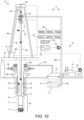
- Figure 10 illustrates drilling of the first wellbore 1a into the geological formation while utilizing the function 27 and/or the second function 42, according to another embodiment of the present disclosure.
- either or both functions 27,40 may be determined before the drilling operation and provided to the PLC 2p.
- the performance data 43 may also be provided to the PLC 2p before the drilling operation such that the PLC may calculate UCS and/or ACT WOB during the drilling operation of the first wellbore 1a (and/or the second wellbore 1b).
- the PLC 2p may then produce portions of the UCS logs 29a,b and/or the drag log 44 as the respective wellbores are being drilled.
- the drilling engineer may then utilize the real time logs 29a,b,44 to adjust drilling parameters during the drilling operation(s). For example the drilling engineer may utilize the UCS logs 29a,b to adjust the trajectories of the respective wellbores 1a,b during drilling (aka geo-steering).
- the PLC 2p may also generate the real time drag log 44 during drilling of either or both wellbores 1a,b.
- the drilling engineer may utilize the real time drag log to optimize ROP (if ACT WOB is insufficient and needs to be increased) and/or extend life of the drill bit 7 (if ACT WOB is overloading the drill bit and needs to be decreased) by adjusting the ACT WOB.
Landscapes
- Engineering & Computer Science (AREA)
- Geology (AREA)
- Life Sciences & Earth Sciences (AREA)
- Mining & Mineral Resources (AREA)
- Environmental & Geological Engineering (AREA)
- Fluid Mechanics (AREA)
- Physics & Mathematics (AREA)
- General Life Sciences & Earth Sciences (AREA)
- Geochemistry & Mineralogy (AREA)
- Chemical & Material Sciences (AREA)
- Crystallography & Structural Chemistry (AREA)
- Mechanical Engineering (AREA)
- Analytical Chemistry (AREA)
- Earth Drilling (AREA)
Applications Claiming Priority (1)
| Application Number | Priority Date | Filing Date | Title |
|---|---|---|---|
| US202363499820P | 2023-05-03 | 2023-05-03 |
Publications (2)
| Publication Number | Publication Date |
|---|---|
| EP4459096A2 true EP4459096A2 (fr) | 2024-11-06 |
| EP4459096A3 EP4459096A3 (fr) | 2025-01-08 |
Family
ID=90971401
Family Applications (1)
| Application Number | Title | Priority Date | Filing Date |
|---|---|---|---|
| EP24173893.9A Pending EP4459096A3 (fr) | 2023-05-03 | 2024-05-02 | Détermination de la résistance à la compression non confinée à partir de données de forage et de paramètres de trépan |
Country Status (2)
| Country | Link |
|---|---|
| US (1) | US20240368976A1 (fr) |
| EP (1) | EP4459096A3 (fr) |
Cited By (1)
| Publication number | Priority date | Publication date | Assignee | Title |
|---|---|---|---|---|
| CN120119887A (zh) * | 2025-03-11 | 2025-06-10 | 中国矿业大学(北京) | 地下工程智能探锚系统与方法 |
Citations (7)
| Publication number | Priority date | Publication date | Assignee | Title |
|---|---|---|---|---|
| US4914591A (en) | 1988-03-25 | 1990-04-03 | Amoco Corporation | Method of determining rock compressive strength |
| US7555414B2 (en) | 2004-12-16 | 2009-06-30 | Chevron U.S.A. Inc. | Method for estimating confined compressive strength for rock formations utilizing skempton theory |
| US8082104B2 (en) | 2009-01-23 | 2011-12-20 | Varel International Ind., L.P. | Method to determine rock properties from drilling logs |
| US9556728B2 (en) | 2014-01-13 | 2017-01-31 | Varel Europe S.A.S. | Methods and systems of analyzing wellbore drilling operations |
| US10094210B2 (en) | 2013-10-01 | 2018-10-09 | Rocsol Technologies Inc. | Drilling system |
| US10963600B2 (en) | 2015-07-09 | 2021-03-30 | Conocophillips Company | Rock strength and in-situ stresses from drilling response |
| US11905828B1 (en) | 2022-07-27 | 2024-02-20 | Halliburton Energy Services, Inc. | Monitoring drilling conditions and estimating rock properties |
Family Cites Families (5)
| Publication number | Priority date | Publication date | Assignee | Title |
|---|---|---|---|---|
| US6460631B2 (en) * | 1999-08-26 | 2002-10-08 | Baker Hughes Incorporated | Drill bits with reduced exposure of cutters |
| US6879947B1 (en) * | 1999-11-03 | 2005-04-12 | Halliburton Energy Services, Inc. | Method for optimizing the bit design for a well bore |
| SA113340567B1 (ar) * | 2012-10-26 | 2015-07-07 | بيكر هوغيس انكوربوريتد | نظام وطريقة لمعالجة بيانات بئر باستخدام تحليل بيانات توبولوجية. |
| US9022140B2 (en) * | 2012-10-31 | 2015-05-05 | Resource Energy Solutions Inc. | Methods and systems for improved drilling operations using real-time and historical drilling data |
| AU2020425706B2 (en) * | 2020-01-29 | 2025-05-22 | Halliburton Energy Services, Inc. | Trajectory control for directional drilling using formation evaluation measurement feedback |
-
2024
- 2024-04-12 US US18/634,392 patent/US20240368976A1/en active Pending
- 2024-05-02 EP EP24173893.9A patent/EP4459096A3/fr active Pending
Patent Citations (7)
| Publication number | Priority date | Publication date | Assignee | Title |
|---|---|---|---|---|
| US4914591A (en) | 1988-03-25 | 1990-04-03 | Amoco Corporation | Method of determining rock compressive strength |
| US7555414B2 (en) | 2004-12-16 | 2009-06-30 | Chevron U.S.A. Inc. | Method for estimating confined compressive strength for rock formations utilizing skempton theory |
| US8082104B2 (en) | 2009-01-23 | 2011-12-20 | Varel International Ind., L.P. | Method to determine rock properties from drilling logs |
| US10094210B2 (en) | 2013-10-01 | 2018-10-09 | Rocsol Technologies Inc. | Drilling system |
| US9556728B2 (en) | 2014-01-13 | 2017-01-31 | Varel Europe S.A.S. | Methods and systems of analyzing wellbore drilling operations |
| US10963600B2 (en) | 2015-07-09 | 2021-03-30 | Conocophillips Company | Rock strength and in-situ stresses from drilling response |
| US11905828B1 (en) | 2022-07-27 | 2024-02-20 | Halliburton Energy Services, Inc. | Monitoring drilling conditions and estimating rock properties |
Non-Patent Citations (2)
| Title |
|---|
| HONGKE GAO: "Relationship between rock uniaxial compressive strength and digital core drilling parameters and its forecast method", INT J COAL SCI TECHNOL, vol. 8, no. 4, 2021, pages 605 - 613 |
| SAJJAD KALANTARI: "Estimating rock strength parameters using drilling data", INTERNATIONAL JOURNAL OF ROCK MECHANICS AND MINING SCIENCES, vol. 104, 2018, pages 45 - 52 |
Cited By (2)
| Publication number | Priority date | Publication date | Assignee | Title |
|---|---|---|---|---|
| CN120119887A (zh) * | 2025-03-11 | 2025-06-10 | 中国矿业大学(北京) | 地下工程智能探锚系统与方法 |
| CN120119887B (zh) * | 2025-03-11 | 2025-09-02 | 中国矿业大学(北京) | 地下工程智能探锚系统与方法 |
Also Published As
| Publication number | Publication date |
|---|---|
| US20240368976A1 (en) | 2024-11-07 |
| EP4459096A3 (fr) | 2025-01-08 |
Similar Documents
| Publication | Publication Date | Title |
|---|---|---|
| EP3385497B1 (fr) | Procédé d'optimisation d'une opération de forage utilisant des données empiriques | |
| Huh et al. | Enhanced Geothermal Systems (EGS) well construction technology evaluation report. | |
| Hareland et al. | Calculating unconfined rock strength from drilling data | |
| Kerkar et al. | Estimation of rock compressive strength using downhole weight-on-bit and drilling models | |
| CA2935247A1 (fr) | Modele permettant d'estimer l'usure d'un outil de forage | |
| AU2020355349B2 (en) | Rate of penetration drilling operation controller | |
| Shelkholeslami et al. | Drilling and production aspects of horizontal wells in the Austin Chalk | |
| EP4459096A2 (fr) | Détermination de la résistance à la compression non confinée à partir de données de forage et de paramètres de trépan | |
| Prassl | Drilling Engineering | |
| Nguyen | Drilling | |
| US8799198B2 (en) | Borehole drilling optimization with multiple cutting structures | |
| Jebur | Directional Drilling Tools Assessment and the Impact of Bottom Hole Assembly Configuration on the Well Trajectory and Operation Optimization | |
| Prasad et al. | An Innovative and Reliable Method of Estimating Rock Strength From Drilling Data Acquired Downhole | |
| Amorer et al. | Surface hydraulic fracturing trial at Cadia East | |
| Sperber et al. | Drilling into geothermal reservoirs | |
| Skinner et al. | Coring at extreme temperatures, design and operation of a core barrel for the Iceland Deep Drilling Project (IDDP) | |
| Kolmer et al. | Using Drilling Data of Offset Wells and Core Data to Optimize Perforation Selection for the Caney Shale | |
| Al Hindi et al. | Quantifying Hole Cleaning in Real-Time Optimizes Drilling Performance and Demonstrably Reduces NPT and ILT in a Complex Multilateral Well | |
| Stavychnyi et al. | Specific features and prospects of well recovery by sidetracking based on the example of the Stynava field | |
| Fasheloum | Investigation of drilling parameters indicators | |
| Villeneuve et al. | Informing deep geothermal reservoir rock mass properties from drilling data-experience from Krafla, Iceland | |
| Florence et al. | Drillers' notes | |
| NEDJAH et al. | Fundamentals And Techniques of coiled tubing drilling CTD | |
| WO2025137240A9 (fr) | Procédé et processus de modélisation et de suivi d'usure de complétion d'une tâche à l'autre | |
| WO2025137240A1 (fr) | Procédé et processus de modélisation et de suivi d'usure de complétion d'une tâche à l'autre |
Legal Events
| Date | Code | Title | Description |
|---|---|---|---|
| PUAI | Public reference made under article 153(3) epc to a published international application that has entered the european phase |
Free format text: ORIGINAL CODE: 0009012 |
|
| STAA | Information on the status of an ep patent application or granted ep patent |
Free format text: STATUS: THE APPLICATION HAS BEEN PUBLISHED |
|
| AK | Designated contracting states |
Kind code of ref document: A2 Designated state(s): AL AT BE BG CH CY CZ DE DK EE ES FI FR GB GR HR HU IE IS IT LI LT LU LV MC ME MK MT NL NO PL PT RO RS SE SI SK SM TR |
|
| PUAL | Search report despatched |
Free format text: ORIGINAL CODE: 0009013 |
|
| AK | Designated contracting states |
Kind code of ref document: A3 Designated state(s): AL AT BE BG CH CY CZ DE DK EE ES FI FR GB GR HR HU IE IS IT LI LT LU LV MC ME MK MT NL NO PL PT RO RS SE SI SK SM TR |
|
| RIC1 | Information provided on ipc code assigned before grant |
Ipc: E21B 43/26 20060101ALI20241202BHEP Ipc: E21B 33/134 20060101ALI20241202BHEP Ipc: E21B 7/06 20060101ALI20241202BHEP Ipc: E21B 49/00 20060101ALI20241202BHEP Ipc: E21B 44/00 20060101AFI20241202BHEP |
|
| STAA | Information on the status of an ep patent application or granted ep patent |
Free format text: STATUS: REQUEST FOR EXAMINATION WAS MADE |
|
| 17P | Request for examination filed |
Effective date: 20250227 |
|
| STAA | Information on the status of an ep patent application or granted ep patent |
Free format text: STATUS: EXAMINATION IS IN PROGRESS |
|
| 17Q | First examination report despatched |
Effective date: 20260116 |