EP4459100A1 - Moteur à air avec temps de maintien augmenté à l'extension d'aube maximale - Google Patents
Moteur à air avec temps de maintien augmenté à l'extension d'aube maximale Download PDFInfo
- Publication number
- EP4459100A1 EP4459100A1 EP24173338.5A EP24173338A EP4459100A1 EP 4459100 A1 EP4459100 A1 EP 4459100A1 EP 24173338 A EP24173338 A EP 24173338A EP 4459100 A1 EP4459100 A1 EP 4459100A1
- Authority
- EP
- European Patent Office
- Prior art keywords
- rotor
- vanes
- pneumatic motor
- stator
- wall
- Prior art date
- Legal status (The legal status is an assumption and is not a legal conclusion. Google has not performed a legal analysis and makes no representation as to the accuracy of the status listed.)
- Pending
Links
Images





Classifications
-
- F—MECHANICAL ENGINEERING; LIGHTING; HEATING; WEAPONS; BLASTING
- F01—MACHINES OR ENGINES IN GENERAL; ENGINE PLANTS IN GENERAL; STEAM ENGINES
- F01C—ROTARY-PISTON OR OSCILLATING-PISTON MACHINES OR ENGINES
- F01C1/00—Rotary-piston machines or engines
- F01C1/30—Rotary-piston machines or engines having the characteristics covered by two or more groups F01C1/02, F01C1/08, F01C1/22, F01C1/24 or having the characteristics covered by one of these groups together with some other type of movement between co-operating members
- F01C1/34—Rotary-piston machines or engines having the characteristics covered by two or more groups F01C1/02, F01C1/08, F01C1/22, F01C1/24 or having the characteristics covered by one of these groups together with some other type of movement between co-operating members having the movement defined in group F01C1/08 or F01C1/22 and relative reciprocation between the co-operating members
- F01C1/344—Rotary-piston machines or engines having the characteristics covered by two or more groups F01C1/02, F01C1/08, F01C1/22, F01C1/24 or having the characteristics covered by one of these groups together with some other type of movement between co-operating members having the movement defined in group F01C1/08 or F01C1/22 and relative reciprocation between the co-operating members with vanes reciprocating with respect to the inner member
-
- F—MECHANICAL ENGINEERING; LIGHTING; HEATING; WEAPONS; BLASTING
- F01—MACHINES OR ENGINES IN GENERAL; ENGINE PLANTS IN GENERAL; STEAM ENGINES
- F01C—ROTARY-PISTON OR OSCILLATING-PISTON MACHINES OR ENGINES
- F01C21/00—Component parts, details or accessories not provided for in groups F01C1/00 - F01C20/00
- F01C21/08—Rotary pistons
- F01C21/0809—Construction of vanes or vane holders
- F01C21/0818—Vane tracking; control therefor
- F01C21/0827—Vane tracking; control therefor by mechanical means
- F01C21/0836—Vane tracking; control therefor by mechanical means comprising guiding means, e.g. cams, rollers
-
- B—PERFORMING OPERATIONS; TRANSPORTING
- B25—HAND TOOLS; PORTABLE POWER-DRIVEN TOOLS; MANIPULATORS
- B25D—PERCUSSIVE TOOLS
- B25D11/00—Portable percussive tools with electromotor or other motor drive
- B25D11/06—Means for driving the impulse member
- B25D11/066—Means for driving the impulse member using centrifugal or rotary impact elements
-
- F—MECHANICAL ENGINEERING; LIGHTING; HEATING; WEAPONS; BLASTING
- F01—MACHINES OR ENGINES IN GENERAL; ENGINE PLANTS IN GENERAL; STEAM ENGINES
- F01C—ROTARY-PISTON OR OSCILLATING-PISTON MACHINES OR ENGINES
- F01C1/00—Rotary-piston machines or engines
- F01C1/30—Rotary-piston machines or engines having the characteristics covered by two or more groups F01C1/02, F01C1/08, F01C1/22, F01C1/24 or having the characteristics covered by one of these groups together with some other type of movement between co-operating members
- F01C1/34—Rotary-piston machines or engines having the characteristics covered by two or more groups F01C1/02, F01C1/08, F01C1/22, F01C1/24 or having the characteristics covered by one of these groups together with some other type of movement between co-operating members having the movement defined in group F01C1/08 or F01C1/22 and relative reciprocation between the co-operating members
- F01C1/344—Rotary-piston machines or engines having the characteristics covered by two or more groups F01C1/02, F01C1/08, F01C1/22, F01C1/24 or having the characteristics covered by one of these groups together with some other type of movement between co-operating members having the movement defined in group F01C1/08 or F01C1/22 and relative reciprocation between the co-operating members with vanes reciprocating with respect to the inner member
- F01C1/348—Rotary-piston machines or engines having the characteristics covered by two or more groups F01C1/02, F01C1/08, F01C1/22, F01C1/24 or having the characteristics covered by one of these groups together with some other type of movement between co-operating members having the movement defined in group F01C1/08 or F01C1/22 and relative reciprocation between the co-operating members with vanes reciprocating with respect to the inner member the vanes positively engaging, with circumferential play, an outer rotatable member
-
- F—MECHANICAL ENGINEERING; LIGHTING; HEATING; WEAPONS; BLASTING
- F01—MACHINES OR ENGINES IN GENERAL; ENGINE PLANTS IN GENERAL; STEAM ENGINES
- F01C—ROTARY-PISTON OR OSCILLATING-PISTON MACHINES OR ENGINES
- F01C13/00—Adaptations of machines or engines for special use; Combinations of engines with devices driven thereby
- F01C13/02—Adaptations of machines or engines for special use; Combinations of engines with devices driven thereby for driving hand-held tools or the like
-
- F—MECHANICAL ENGINEERING; LIGHTING; HEATING; WEAPONS; BLASTING
- F01—MACHINES OR ENGINES IN GENERAL; ENGINE PLANTS IN GENERAL; STEAM ENGINES
- F01C—ROTARY-PISTON OR OSCILLATING-PISTON MACHINES OR ENGINES
- F01C21/00—Component parts, details or accessories not provided for in groups F01C1/00 - F01C20/00
- F01C21/003—Systems for the equilibration of forces acting on the elements of the machine
- F01C21/006—Equalization of pressure pulses
-
- F—MECHANICAL ENGINEERING; LIGHTING; HEATING; WEAPONS; BLASTING
- F01—MACHINES OR ENGINES IN GENERAL; ENGINE PLANTS IN GENERAL; STEAM ENGINES
- F01C—ROTARY-PISTON OR OSCILLATING-PISTON MACHINES OR ENGINES
- F01C21/00—Component parts, details or accessories not provided for in groups F01C1/00 - F01C20/00
- F01C21/10—Outer members for co-operation with rotary pistons; Casings
- F01C21/104—Stators; Members defining the outer boundaries of the working chamber
- F01C21/106—Stators; Members defining the outer boundaries of the working chamber with a radial surface, e.g. cam rings
-
- F—MECHANICAL ENGINEERING; LIGHTING; HEATING; WEAPONS; BLASTING
- F01—MACHINES OR ENGINES IN GENERAL; ENGINE PLANTS IN GENERAL; STEAM ENGINES
- F01C—ROTARY-PISTON OR OSCILLATING-PISTON MACHINES OR ENGINES
- F01C20/00—Control of, monitoring of, or safety arrangements for, machines or engines
- F01C20/04—Control of, monitoring of, or safety arrangements for, machines or engines specially adapted for reversible machines or engines
-
- F—MECHANICAL ENGINEERING; LIGHTING; HEATING; WEAPONS; BLASTING
- F04—POSITIVE - DISPLACEMENT MACHINES FOR LIQUIDS; PUMPS FOR LIQUIDS OR ELASTIC FLUIDS
- F04C—ROTARY-PISTON, OR OSCILLATING-PISTON, POSITIVE-DISPLACEMENT MACHINES FOR LIQUIDS; ROTARY-PISTON, OR OSCILLATING-PISTON, POSITIVE-DISPLACEMENT PUMPS
- F04C2250/00—Geometry
- F04C2250/30—Geometry of the stator
-
- F—MECHANICAL ENGINEERING; LIGHTING; HEATING; WEAPONS; BLASTING
- F04—POSITIVE - DISPLACEMENT MACHINES FOR LIQUIDS; PUMPS FOR LIQUIDS OR ELASTIC FLUIDS
- F04C—ROTARY-PISTON, OR OSCILLATING-PISTON, POSITIVE-DISPLACEMENT MACHINES FOR LIQUIDS; ROTARY-PISTON, OR OSCILLATING-PISTON, POSITIVE-DISPLACEMENT PUMPS
- F04C2270/00—Control; Monitoring or safety arrangements
- F04C2270/12—Vibration
-
- F—MECHANICAL ENGINEERING; LIGHTING; HEATING; WEAPONS; BLASTING
- F04—POSITIVE - DISPLACEMENT MACHINES FOR LIQUIDS; PUMPS FOR LIQUIDS OR ELASTIC FLUIDS
- F04C—ROTARY-PISTON, OR OSCILLATING-PISTON, POSITIVE-DISPLACEMENT MACHINES FOR LIQUIDS; ROTARY-PISTON, OR OSCILLATING-PISTON, POSITIVE-DISPLACEMENT PUMPS
- F04C2270/00—Control; Monitoring or safety arrangements
- F04C2270/13—Noise
-
- F—MECHANICAL ENGINEERING; LIGHTING; HEATING; WEAPONS; BLASTING
- F04—POSITIVE - DISPLACEMENT MACHINES FOR LIQUIDS; PUMPS FOR LIQUIDS OR ELASTIC FLUIDS
- F04C—ROTARY-PISTON, OR OSCILLATING-PISTON, POSITIVE-DISPLACEMENT MACHINES FOR LIQUIDS; ROTARY-PISTON, OR OSCILLATING-PISTON, POSITIVE-DISPLACEMENT PUMPS
- F04C2270/00—Control; Monitoring or safety arrangements
- F04C2270/14—Pulsations
-
- F—MECHANICAL ENGINEERING; LIGHTING; HEATING; WEAPONS; BLASTING
- F04—POSITIVE - DISPLACEMENT MACHINES FOR LIQUIDS; PUMPS FOR LIQUIDS OR ELASTIC FLUIDS
- F04C—ROTARY-PISTON, OR OSCILLATING-PISTON, POSITIVE-DISPLACEMENT MACHINES FOR LIQUIDS; ROTARY-PISTON, OR OSCILLATING-PISTON, POSITIVE-DISPLACEMENT PUMPS
- F04C29/00—Component parts, details or accessories of pumps or pumping installations, not provided for in groups F04C18/00 - F04C28/00
- F04C29/06—Silencing
Definitions
- Pneumatic rotary tools include pneumatic motors that receive compressed air and convert energy from the compressed air into mechanical work.
- the mechanical work produced by the pneumatic motor may be converted in the form of rotary motion or linear motion.
- Pneumatic motors that produce rotary motion include vane-type pneumatic motors, piston pneumatic motors, air turbines, and gear-type motors.
- Vane-type motors also called rotary vane motors, are a type of pneumatic motor that uses a compressed fluid (typically compressed air) to produce rotational motion to rotate a shaft.
- Rotary vane motors include a slotted rotor eccentrically mounted on a stator. The rotor includes radially extending vanes extending from the slots around rotor. In typical pneumatic motors, the vanes extending from the rotor reach their full extension, or open at their maximum reveal, at one point along the length of travel, for example, only when reaching one-hundred and eighty degrees (180°) of rotation from the bottom of the rotor.
- either the length of the motor or the diameter of the rotor and the stator may be increased.
- the pneumatic motor described herein includes a stator where the arc of the stator bore allows the vanes to fully extend before reaching one-hundred and eighty degrees (180°) (e.g., with respect to a tangential point/line between the rotor and the stator) and to remain extended for a longer duration of the cycle along the rotation of the rotor.
- This longer period of full vane extension allows the vane to be driven and maintained at a higher pressure and force throughout the duration of an arc length, resulting in an increase in motor torque when compared to a typical pneumatic motor having a cylindrical stator.
- the moment arm of the force resulting from the pressure differential e.g., the difference in pressure from one side of the vane to the other acting at the centroid of the pressurized portion of the vane
- This increase in the moment arm provided by the vanes about the axis of rotation also increases the resulting torque of the pneumatic motor.
- the stator bore of the pneumatic motor described herein increases the performance of the pneumatic motor without adding additional weight to the pneumatic motor. Additionally, the pneumatic motor described herein does not require a change to the flow paths leading to and from the pneumatic motor. Additionally, example embodiments of the pneumatic motor reduce the jerk of the rotor as it accelerates and decelerates.
- FIG. 1 shows an illustrative embodiment of the power tool assembly 100 in accordance with the present disclosure.
- the power tool assembly 100 includes a housing 102 having a front end 101 and a rear end 103 .
- the power tool assembly 100 may include a hammercase 104 that houses an impact assembly 110 .
- the housing 102 houses the pneumatic motor 120 .
- the pneumatic motor 120 receives a flow of high pressure air and produces a resulting torque and rotational speed that rotates a shaft 106 coupled to the impact assembly 110 around an output axis 100A .
- the output axis 100A extends from the front end 101 to the rear end 103 .
- the flow of high pressure air is supplied to the power tool assembly 100 from a compressed air source, for example, an air compressor (not shown) coupled to the power tool assembly 100 .
- the power tool assembly 100 is configured to receive the compressed air from the compressed air source to actuate the pneumatic motor 120 .
- the power tool assembly 100 may use a different compressed fluid as a medium to rotate the pneumatic motor 120 .
- the power tool assembly 100 may be coupled to a source of compressed nitrogen or other compressed gas supplies the energy to rotate the pneumatic motor 120 .
- the power tool assembly 100 is an impact wrench.
- the power tool assembly 100 may be selected from a group including, but not limited to, pulse tools, torque wrenches, screwdrivers, drills, grinders, sanders, tire changers, and other pneumatic tools that uses a vane-type pneumatic motor.
- the pneumatic motor 120 may be included in other industrial applications including, but not limited to, hoists, winches, engine starters, and other equipment/machinery using compressed air to drive a rotor.
- the pneumatic motor 120 may also be used as a freestanding pneumatic motor employed in industrial, manufacturing, and commercial applications where a compressed air source drives a rotor to deliver a torque.
- the power tool assembly 100 may further include a rear end plate 112 and a front end plate 114 disposed in proximity to the pneumatic motor 120 and configured to limit axial displacement of the pneumatic motor 120 within the housing 102 .
- the rear end plate 112 and the front end plate 114 may include bearings 116 that allow the rotation of the pneumatic motor 120 around the output axis 100A .
- the housing 102 may include a gear set assembly (not shown) connecting the pneumatic motor 120 with the impact assembly 110 .
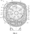
- the pneumatic motor 120 includes a stator 124 having a stator inner wall 125 that defines a stator bore 126 .
- the stator bore 126 houses an eccentrically mounted rotor 122 having a plurality of slots 123 around the circumference of the rotor 122 .
- the plurality of slots 123 holds a plurality of vanes 128 disposed around the rotor 122 , where each one of the plurality of vanes 128 includes a vane leading edge 127 .
- the plurality of vanes 128 extends radially from the rotor 122 and is configured to slide in and out of the respective plurality of slots 123 as the rotor 122 rotates within the stator bore 126 .
- the plurality of vanes 128 may extend from the plurality of slots 123 using the air pressure from the flow of high pressure air or may use a biasing component disposed within the plurality of slots 123 , such as but not limited to springs (not shown), etc. When extended, the plurality of vanes 128 closes off the space between the rotor 122 and the stator inner wall 125 .
- the pneumatic motor 120 is an offset vane motor.
- the rotor 122 is coaxial with and rotates about the output axis 100A .
- the pneumatic motor 120 further includes an air inlet 130 , a primary air outlet 132 , and a residual air outlet 134 , as shown in FIGS. 2 and 3 .
- the air inlet 130 is in fluid communication with at least one air inlet opening 142 located on the stator inner wall 125 .
- the residual air outlet 134 is in fluid communication with at least one residual air outlet opening 144 located on the stator inner wall 125 opposite to the at least one air inlet opening 142 .
- the air inlet 130 , the primary air outlet 132 , and the residual air outlet 134 may be disposed in the rear end plate 112 and/or the front end plate 114 .
- angular rotation e.g., 90°, 180°, etc.
- angular rotation e.g., 90°, 180°, etc.
- the rotor 122 is rotating in a counterclockwise direction as viewed from the perspective of FIG. 2 .
- angular measurements can either be absolute or relative measurements depending on the context, where the absolute angular measurements are referenced starting at a tangential line 136 (where the rotor 122 and the stator inner wall 125 are tangent to each other) at zero degrees (0°) angle and which progresses in a counterclockwise direction.
- the tangential line 136 may be disposed before or after the zero degrees (0°) angle.
- the plurality of vanes 128 As the plurality of vanes 128 rotates over the at least one air inlet opening 142 , the plurality of vanes 128 traps a pocket of compressed air between adjacent vanes that is then transported to the primary air outlet 132 . Prior to being exhausted through the primary air outlet 132 , the pressure of the compressed air exerts a force on the plurality of vanes 128 . As the force exerted on the plurality of vanes increases, so does the resultant torque supplied by the pneumatic motor 120 . As the plurality of vanes 128 continues rotating past the primary air outlet 132 , and the chamber volume between adjacent vanes is reduced, there is pressure buildup of the residual air left on the chamber after the primary air outlet 132 . The residual air remaining between adjacent vanes is exhausted through the at least one residual air outlet opening 144 prior to starting the rotational cycle again at the tangential line 136 .
- the plurality of vanes 128 is in contact with the stator inner wall 125 at a point of minimum vane extension R min , where each one of the plurality of vanes 128 is fully or almost fully contained within the respective one of the plurality of slots 123 , for example, at the tangential line 136 .
- the vanes 128 are in contact with the stator inner wall 125 at maximum vane extension R max , when the plurality of vanes 128 are fully extended from the respective plurality of slots 123 .
- the stator inner wall 125 and the stator bore 126 define a dwell region 140 having a leading edge 139 and a trailing edge 141 .
- the vanes 128 remain in maximum vane extension R max throughout the arc length of the dwell region.
- the dwell region 140 covers an arc length around the periphery of the stator bore 126 at which the plurality of vanes 128 extend and remain fully extended.
- the distance between the axis of rotation 100A and the stator inner wall 125 remains constant along the dwell region 140 , making the dwell region 140 a constant radius arc relative to the center of the rotor 122 .
- each one of the plurality of vanes 128 rotates tangentially to the stator inner wall 125 along the dwell region 140 , each one of the plurality of vanes 128 is fully extended along the arc length of the dwell region 140 .
- the plurality of vanes may reach or more closely approach their full extension prior to reaching one-hundred and eighty degrees (180°) of rotation from the tangential line 136 .
- the available vane surface area e.g., the surface area across which the air pressure differential drives the vane
- the available vane surface area increases in comparison to a circular stator inner wall 125 defining a cylindrical stator bore 126 .
- the air pressure force acting on the vanes increases, even if the pressure differential across the vanes remains constant, resulting in an increased resultant motor torque.
- the volume of the compressed air pockets, or chambers, created between adjacent ones of the plurality of vanes 128 and the stator inner wall 125 remains constant as each one of the plurality of vanes 128 approaches the primary air outlet 132 . For this reason, the pressure in each chamber will not decrease as rapidly as it would in a cylindrical stator. Additionally, the compressed air does not need to expand as much from the point past the air inlet opening 142 to the primary air outlet 132 where each one of the plurality of vanes 128 exposes the chamber between adjacent vanes. Thus, the pressure of the chamber between adjacent vanes remains higher relative to the exhaust pressure, providing not only the increased vane area mentioned above, but also an increased pressure differential across the leading vane, which further acts to increase the force on the vane and hence the motor torque.
- the mean radius of the plurality of vanes 128 traveling across the arc length of the dwell region 140 is constant along the entirety of the dwell region 140 .
- the mean radius of the plurality of vanes 128 traveling across the arc length of the dwell region 140 is not constant along the entirety of the dwell region, but the mean radius of the plurality of vanes extends further out from the rotor 122 than the mean radius of vanes in a power tool without a dwell region 140 .
- the resultant of the pressure force acts at a slightly increased radius about the axis of rotation 100A for the arc length of the dwell region 140 .
- the pneumatic motor 120 allows for a higher motor torque to be generated without a significant increase in the size of the motor 120 compared to typical motors without a dwell region 140 (e.g., motors with cylindrical stators).
- the stator 124 follows a cam profile on the stator bore 126 and the stator inner wall 125 between the point of minimum vane extension R min and the point of reaching maximum vane extension R max
- the profile of the stator bore 126 and the stator inner wall 125 provides a steady or constant rise from the tangential line 136 or the zero degrees (0°) angle/position until reaching the leading edge 139 of the dwell region 140 .
- the vane acceleration and the derivative of the vane acceleration also referred to as the jerk, may change.
- stator inner wall 125 follow a cam profile allows the plurality of vanes 128 to follow a smooth rise transition between the point of minimum vane extension R min at the tangential line 136 and the leading edge 139 of the dwell region 140 , i.e., the point of reaching the maximum vane extension R max .
- FIG. 2 shows the stator 124 arranged following a cycloidal cam profile or motion curve.
- the stator rotates, the plurality of vanes 128 rises or expands, following a cycloidal cam motion or motion curve.
- the stator 124 may be arranged so that the plurality of vanes 128 follow at least one of a parabolic motion curve, a harmonic motion curve, etc.
- FIG. 5 different embodiments of the cam geometry of the stator inner wall 125 are shown and compared to the standard geometry of a cylindrical stator.
- FIG. 6 shows a graph illustrating the angle of rotation at which the plurality of vanes 128 from the different embodiments (e.g., cycloidal, parabolic, harmonic) of the stator 124 reach their maximum vane extension and the length of rotation through which the maximum vane extension is maintained during the cycle of rotation (e.g., the arc length of the dwell region 140 ).
- the plurality of vanes 128 from the different embodiments e.g., cycloidal, parabolic, harmonic
- the leading edge 139 of the dwell region 140 may be located between one-hundred and twenty degrees (120°) and one-hundred and forty degrees (140°) from the tangential line 136 .
- the trailing edge 141 of the dwell region 140 may be positioned between two-hundred and twenty degrees (220°) and two-hundred and forty degrees (240°) from the tangential line 136 .
- FIG. 1 For example, in the embodiment shown in FIG.
- the leading edge 139 of the dwell region 140 is located at one-hundred and thirty-five degrees (135°) from the tangential line 136
- the trailing edge 141 of the dwell region 140 is located at two-hundred and twenty-five degrees (225°) from the tangential line 136 , making the arc length of the dwell region 140 ninety degrees (90°).
- the dwell region 140 may have an arc length longer than or shorter than ninety degrees (90°).
- the arc length of the dwell region 140 may be forty-five degrees (45°), as shown in FIG. 3 .
- FIG. 3 shows a stator 124 having the leading edge 139 of the dwell region 140 located at one-hundred and thirty-five degrees (135°) from the tangential line 136 , while the trailing edge 141 of the dwell region 140 is positioned at one-hundred and eighty degrees (180°) from the tangential line 136 , coinciding with the primary air outlet 132 .
- leading edge 139 of the dwell region 140 may be located before or after one-hundred and thirty-five degrees (135°), while the trailing edge 141 of the dwell region 140 may be located before or after two-hundred and twenty-five degrees (225°).
- the primary air outlet 132 is disposed above the rotor 122 opposite to the tangential line 136 of the rotor 122 and the stator 124 .
- the primary air outlet 132 may be disposed at the one-hundred and eighty degrees (180°) position as shown in FIGS. 2 through 4 .
- the primary air outlet 132 may be located towards one of the leading edge 139 or the trailing edge 141 of the dwell region 140 .
- the primary air outlet 132 may be located at the one-hundred and ninety degrees (190°) position (not shown).
- a fastener is rotated clockwise to be fastened and rotated counterclockwise to be unfastened.
- the pneumatic motor 120 may be biased towards a direction of rotation (forward biased, reverse biased).
- FIG. 3 shows a reverse biased power tool 100 .
- an increased torque is supplied by the pneumatic motor 120 as the plurality of vanes 128 are fully extended while traveling through the dwell region 140 prior to reaching the primary air outlet 132 and releasing the compressed air.
- the plurality of vanes 128 are not fully extended until reaching the dwell region 140 at one-hundred and eighty degrees (180°) from the tangential line 136 . Since the vanes 128 are not extended prior to the release of the compressed air through the primary air outlet 132 , less torque is exerted by the motor 120 in comparison with the counterclockwise rotation.
- the power tool may be reverse biased in order to provide a stronger torque when a user is unfastening a fastener (not shown).
- the trailing edge 141 of the dwell region 140 coincides with the primary air outlet 132 .
- the trailing edge 141 of the dwell region and the primary air outlet 132 may be located at one-hundred and eighty degrees (180°) from the tangential line 136 .
- the pneumatic motor 120 may be forward biased.
- the leading edge 139 of the dwell region 140 may coincide with the primary air outlet 132 .
- the leading edge 139 of the dwell region and the primary air outlet 132 may be located at one-hundred and eighty degrees (180°) from the tangential line 136 .
- the position of the primary air outlet 132 is an example embodiment, and the primary air outlet may be disposed at a different angle from the tangential line 136 .
- FIG. 7 shows a comparison of the resulting torque of the example embodiment shown in FIG. 2 compared to the resulting torque of a pneumatic motor having a cylindrical stator.
- the pneumatic motor 120 having the cycloidal stator 124 provides an increase in torque magnitude (higher torque) and a reduced torque variation compared to the pneumatic motor having a cylindrical stator. Having reduced torque variation, or a more constant torque, may be beneficial in torque control settings.
- a user or a controller (not shown) in communication with the power tool 100 may be able to accurately assess the number of impacts needed to exert on a fastener to reach the desired torque.
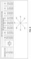
- FIG. 8 different example embodiments of the cam profile of the stator 124 and stator bore 126 are compared, including a cylindrical cam profile (CYL), a linear cam profile (LIN), a parabolic cam profile (PAR), a harmonic cam profile (HAR), and a cycloidal cam profile (CYC).
- the chart shows a calculated motor performance or stall torque (the torque exerted by the pneumatic motor when the output rotational speed is zero) of the different cam profile embodiments based on different angles from the tangential line 136 zero degrees (0°) at which the point of maximum vane extension is reached.
- a pneumatic motor 120 having stator with a cycloidal cam profile has the largest stall torque when the maximum vane extension is reached at one-hundred and thirty-five degrees (135°) from the tangential line 136 , with 42.33 In-Lbs.
- each one of the plurality of vanes 128 may rise and/or fall as their position/angle with respect to the tangential line 136 changes.
- the pneumatic motor 120 may be configured to have a reduced jerk as it accelerates and decelerates the power tool 100 .
- Jerk is the rate of change of an object's acceleration over time. Jerk is undesirable as it is associated with a resulting impact, which contributes to noise, surface wear of the plurality of vanes 128 , and fatigue of the pneumatic motor 120 . Since the angle of the rotor 122 changes with time at angular velocity ⁇ , a vane radial velocity, a radial acceleration, and the radial jerk or "pulse" are defined.
- d 2 rise dt 2 drise d ⁇ d 2 ⁇ dt 2 + d 2 rise d ⁇ 2 d ⁇ dt 2
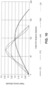
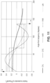
- FIGS. 9 through 12 illustrate vane dynamics of the plurality of vanes 128 following example embodiments of the rise geometries/cam profiles discussed previously and shown in FIG. 5 , with the addition of a linear rise (LIN) cam profile.
- the graphs show plots of rise and its derivatives versus rotor angle.
- FIG. 9 illustrates the rise of the plurality of vanes 128 with respect to the angle from the tangential line 136 (tangency).
- FIG. 10 illustrates the velocity of the plurality of vanes 128 with respect to the angle from tangency.
- FIG. 11 illustrates the acceleration of the plurality of vanes 128 with respect to the angle from tangency.
- FIG. 12 illustrates the jerk of the plurality of vanes 128 with respect to the angle from tangency.
- the radial acceleration of the plurality of vanes 128 is illustrated with respect to the angle of rotation of the rotor 122 .
- all rise types cam geometries
- the cycloid and the linear rise, which had infinite accelerations at the end points
- the dwell region 140 extends over a constant radius, there is zero (0) radial velocity and zero (0) radial acceleration at the dwell region 140 .
- the zero radial velocity and radial acceleration affect the jerk of the pneumatic motor 120 .
- the radial jerk for all rise types have infinite spikes of jerk or pulse that occur when the dwell region 140 is reached (and in the parabolic trace, hidden behind the linear trace with zero value, there is a negative spike halfway to the dwell where the acceleration changes signs).
- the spikes occur because all cam profiles, except for the cycloidal cam profile, have finite accelerations just prior to reaching the dwell region 140 , while at the dwell region 140 the radial acceleration and velocity are zero.
- This change from finite to zero acceleration causes "infinite” jerk or pulse through each one of the plurality of vanes 128 as they extend from the respective plurality of slots 123 following the inner wall surface 125 , shocking the plurality of vanes 128 and potentially impacting their life.
- Use of the cycloidal cam profile in example embodiments of the pneumatic motor 120 may eliminate the "infinite” jerk, providing a finite value as the transition from the rise to the dwell occurs and extending the life of the plurality of vanes 128 .
Landscapes
- Engineering & Computer Science (AREA)
- Mechanical Engineering (AREA)
- General Engineering & Computer Science (AREA)
- Physics & Mathematics (AREA)
- Fluid Mechanics (AREA)
- Hydraulic Motors (AREA)
Applications Claiming Priority (2)
| Application Number | Priority Date | Filing Date | Title |
|---|---|---|---|
| US202363464402P | 2023-05-05 | 2023-05-05 | |
| US18/647,445 US20240368992A1 (en) | 2023-05-05 | 2024-04-26 | Air motor with increased dwell at max vane extension |
Publications (1)
| Publication Number | Publication Date |
|---|---|
| EP4459100A1 true EP4459100A1 (fr) | 2024-11-06 |
Family
ID=90924757
Family Applications (1)
| Application Number | Title | Priority Date | Filing Date |
|---|---|---|---|
| EP24173338.5A Pending EP4459100A1 (fr) | 2023-05-05 | 2024-04-30 | Moteur à air avec temps de maintien augmenté à l'extension d'aube maximale |
Country Status (2)
| Country | Link |
|---|---|
| US (1) | US20240368992A1 (fr) |
| EP (1) | EP4459100A1 (fr) |
Citations (5)
| Publication number | Priority date | Publication date | Assignee | Title |
|---|---|---|---|---|
| GB534510A (en) * | 1939-03-08 | 1941-03-07 | Thompson Prod Inc | Improvements in or relating to pumps of the sliding vane type |
| US2347944A (en) * | 1942-05-22 | 1944-05-02 | Fowler Elbert | Rotary pump |
| GB1413427A (en) * | 1973-04-18 | 1975-11-12 | Atlas Copco Ab | Reversible pneumatic sliding vane rotary motor |
| US4616984A (en) * | 1984-03-14 | 1986-10-14 | Nippondenso Co., Ltd. | Sliding-vane rotary compressor with specific cylinder bore profile |
| DE19848307A1 (de) * | 1997-10-16 | 1999-04-22 | Kit Systems Ltd | Motoren und Pumpen |
Family Cites Families (4)
| Publication number | Priority date | Publication date | Assignee | Title |
|---|---|---|---|---|
| US2733687A (en) * | 1956-02-07 | schmid | ||
| US5310326A (en) * | 1992-09-14 | 1994-05-10 | Mainstream Engineering Corporation | Rotary compressor with improved bore configuration and lubrication system |
| US5525842A (en) * | 1994-12-02 | 1996-06-11 | Volt-Aire Corporation | Air tool with integrated generator and light ring assembly |
| US7222680B2 (en) * | 2004-12-01 | 2007-05-29 | Ingersoll-Rand Company | Pneumatic motor improvements and pneumatic tools incorporating same |
-
2024
- 2024-04-26 US US18/647,445 patent/US20240368992A1/en active Pending
- 2024-04-30 EP EP24173338.5A patent/EP4459100A1/fr active Pending
Patent Citations (5)
| Publication number | Priority date | Publication date | Assignee | Title |
|---|---|---|---|---|
| GB534510A (en) * | 1939-03-08 | 1941-03-07 | Thompson Prod Inc | Improvements in or relating to pumps of the sliding vane type |
| US2347944A (en) * | 1942-05-22 | 1944-05-02 | Fowler Elbert | Rotary pump |
| GB1413427A (en) * | 1973-04-18 | 1975-11-12 | Atlas Copco Ab | Reversible pneumatic sliding vane rotary motor |
| US4616984A (en) * | 1984-03-14 | 1986-10-14 | Nippondenso Co., Ltd. | Sliding-vane rotary compressor with specific cylinder bore profile |
| DE19848307A1 (de) * | 1997-10-16 | 1999-04-22 | Kit Systems Ltd | Motoren und Pumpen |
Also Published As
| Publication number | Publication date |
|---|---|
| US20240368992A1 (en) | 2024-11-07 |
Similar Documents
| Publication | Publication Date | Title |
|---|---|---|
| US4558998A (en) | Variable capacity type vane pump with balancing groove in the cam ring | |
| US7997882B2 (en) | Reduced rotor assembly diameter vane pump | |
| US20240391067A1 (en) | Rotary impact tool | |
| US6422845B1 (en) | Rotary hydraulic vane pump with improved undervane porting | |
| US4799867A (en) | Vane pump with brittle vanes and rough finished housing surface | |
| KR101076362B1 (ko) | 고정형 및 회전형 실린더부를 갖는 베인머시인 | |
| SE454963B (sv) | Momentverktyg av oljeimpulstyp | |
| US20240368992A1 (en) | Air motor with increased dwell at max vane extension | |
| US3584984A (en) | Rotary device | |
| EP2633184B1 (fr) | Dispositif fluidique ayant des compartiments à rouleaux sous pression | |
| EP1210505B1 (fr) | Machine hydraulique rotative | |
| CN118896002A (zh) | 在最大叶片伸出长度处具有增加的维持区域的空气马达 | |
| EP1497537B1 (fr) | Moteur hydraulique | |
| US7421986B2 (en) | Rotary radial internal combustion piston engine | |
| US7255546B1 (en) | Spindle for a vane motor | |
| EP0781924B1 (fr) | Machine à palettes hydraulique | |
| US7588429B2 (en) | Oil pump rotor assembly | |
| WO2011096918A1 (fr) | Machine rotative à aubes ayant usure et perte par frottement réduites | |
| US20020119065A1 (en) | Cartridge vane pump having enhanced cold start performance | |
| GB1565108A (en) | Rotary machine with controlled retactable privoted blade members | |
| EP1710436A1 (fr) | Pompe a engrenages interieurs | |
| CN219733551U (zh) | 一种多进气式摆线气动马达 | |
| JP4257490B2 (ja) | エアモータ | |
| EP4450228A1 (fr) | Outil à impulsions | |
| US20260138242A1 (en) | Power tool with impulse assembly |
Legal Events
| Date | Code | Title | Description |
|---|---|---|---|
| PUAI | Public reference made under article 153(3) epc to a published international application that has entered the european phase |
Free format text: ORIGINAL CODE: 0009012 |
|
| STAA | Information on the status of an ep patent application or granted ep patent |
Free format text: STATUS: REQUEST FOR EXAMINATION WAS MADE |
|
| 17P | Request for examination filed |
Effective date: 20240430 |
|
| AK | Designated contracting states |
Kind code of ref document: A1 Designated state(s): AL AT BE BG CH CY CZ DE DK EE ES FI FR GB GR HR HU IE IS IT LI LT LU LV MC ME MK MT NL NO PL PT RO RS SE SI SK SM TR |
|
| STAA | Information on the status of an ep patent application or granted ep patent |
Free format text: STATUS: EXAMINATION IS IN PROGRESS |
|
| 17Q | First examination report despatched |
Effective date: 20250919 |
|
| GRAP | Despatch of communication of intention to grant a patent |
Free format text: ORIGINAL CODE: EPIDOSNIGR1 |
|
| STAA | Information on the status of an ep patent application or granted ep patent |
Free format text: STATUS: GRANT OF PATENT IS INTENDED |
|
| INTG | Intention to grant announced |
Effective date: 20260601 |