EP4459128A1 - Rotationsverdichter und kühlvorrichtung - Google Patents
Rotationsverdichter und kühlvorrichtung Download PDFInfo
- Publication number
- EP4459128A1 EP4459128A1 EP24729953.0A EP24729953A EP4459128A1 EP 4459128 A1 EP4459128 A1 EP 4459128A1 EP 24729953 A EP24729953 A EP 24729953A EP 4459128 A1 EP4459128 A1 EP 4459128A1
- Authority
- EP
- European Patent Office
- Prior art keywords
- blade
- chamber
- cylinder
- oil
- rotary compressor
- Prior art date
- Legal status (The legal status is an assumption and is not a legal conclusion. Google has not performed a legal analysis and makes no representation as to the accuracy of the status listed.)
- Granted
Links
Images


Classifications
-
- F—MECHANICAL ENGINEERING; LIGHTING; HEATING; WEAPONS; BLASTING
- F04—POSITIVE - DISPLACEMENT MACHINES FOR LIQUIDS; PUMPS FOR LIQUIDS OR ELASTIC FLUIDS
- F04C—ROTARY-PISTON, OR OSCILLATING-PISTON, POSITIVE-DISPLACEMENT MACHINES FOR LIQUIDS; ROTARY-PISTON, OR OSCILLATING-PISTON, POSITIVE-DISPLACEMENT PUMPS
- F04C29/00—Component parts, details or accessories of pumps or pumping installations, not provided for in groups F04C18/00 - F04C28/00
- F04C29/02—Lubrication; Lubricant separation
-
- F—MECHANICAL ENGINEERING; LIGHTING; HEATING; WEAPONS; BLASTING
- F01—MACHINES OR ENGINES IN GENERAL; ENGINE PLANTS IN GENERAL; STEAM ENGINES
- F01C—ROTARY-PISTON OR OSCILLATING-PISTON MACHINES OR ENGINES
- F01C21/00—Component parts, details or accessories not provided for in groups F01C1/00 - F01C20/00
- F01C21/08—Rotary pistons
- F01C21/0809—Construction of vanes or vane holders
-
- F—MECHANICAL ENGINEERING; LIGHTING; HEATING; WEAPONS; BLASTING
- F04—POSITIVE - DISPLACEMENT MACHINES FOR LIQUIDS; PUMPS FOR LIQUIDS OR ELASTIC FLUIDS
- F04C—ROTARY-PISTON, OR OSCILLATING-PISTON, POSITIVE-DISPLACEMENT MACHINES FOR LIQUIDS; ROTARY-PISTON, OR OSCILLATING-PISTON, POSITIVE-DISPLACEMENT PUMPS
- F04C18/00—Rotary-piston pumps specially adapted for elastic fluids
- F04C18/30—Rotary-piston pumps specially adapted for elastic fluids having the characteristics covered by two or more of groups F04C18/02, F04C18/08, F04C18/22, F04C18/24, F04C18/48, or having the characteristics covered by one of these groups together with some other type of movement between co-operating members
- F04C18/34—Rotary-piston pumps specially adapted for elastic fluids having the characteristics covered by two or more of groups F04C18/02, F04C18/08, F04C18/22, F04C18/24, F04C18/48, or having the characteristics covered by one of these groups together with some other type of movement between co-operating members having the movement defined in group F04C18/08 or F04C18/22 and relative reciprocation between the co-operating members
- F04C18/356—Rotary-piston pumps specially adapted for elastic fluids having the characteristics covered by two or more of groups F04C18/02, F04C18/08, F04C18/22, F04C18/24, F04C18/48, or having the characteristics covered by one of these groups together with some other type of movement between co-operating members having the movement defined in group F04C18/08 or F04C18/22 and relative reciprocation between the co-operating members with vanes reciprocating with respect to the outer member
- F04C18/3562—Rotary-piston pumps specially adapted for elastic fluids having the characteristics covered by two or more of groups F04C18/02, F04C18/08, F04C18/22, F04C18/24, F04C18/48, or having the characteristics covered by one of these groups together with some other type of movement between co-operating members having the movement defined in group F04C18/08 or F04C18/22 and relative reciprocation between the co-operating members with vanes reciprocating with respect to the outer member the inner and outer member being in contact along one line or continuous surfaces substantially parallel to the axis of rotation
- F04C18/3564—Rotary-piston pumps specially adapted for elastic fluids having the characteristics covered by two or more of groups F04C18/02, F04C18/08, F04C18/22, F04C18/24, F04C18/48, or having the characteristics covered by one of these groups together with some other type of movement between co-operating members having the movement defined in group F04C18/08 or F04C18/22 and relative reciprocation between the co-operating members with vanes reciprocating with respect to the outer member the inner and outer member being in contact along one line or continuous surfaces substantially parallel to the axis of rotation the surfaces of the inner and outer member, forming the working space, being surfaces of revolution
-
- F—MECHANICAL ENGINEERING; LIGHTING; HEATING; WEAPONS; BLASTING
- F04—POSITIVE - DISPLACEMENT MACHINES FOR LIQUIDS; PUMPS FOR LIQUIDS OR ELASTIC FLUIDS
- F04C—ROTARY-PISTON, OR OSCILLATING-PISTON, POSITIVE-DISPLACEMENT MACHINES FOR LIQUIDS; ROTARY-PISTON, OR OSCILLATING-PISTON, POSITIVE-DISPLACEMENT PUMPS
- F04C18/00—Rotary-piston pumps specially adapted for elastic fluids
- F04C18/30—Rotary-piston pumps specially adapted for elastic fluids having the characteristics covered by two or more of groups F04C18/02, F04C18/08, F04C18/22, F04C18/24, F04C18/48, or having the characteristics covered by one of these groups together with some other type of movement between co-operating members
- F04C18/40—Rotary-piston pumps specially adapted for elastic fluids having the characteristics covered by two or more of groups F04C18/02, F04C18/08, F04C18/22, F04C18/24, F04C18/48, or having the characteristics covered by one of these groups together with some other type of movement between co-operating members having the movement defined in group F04C18/08 or F04C18/22 and having a hinged member
- F04C18/46—Rotary-piston pumps specially adapted for elastic fluids having the characteristics covered by two or more of groups F04C18/02, F04C18/08, F04C18/22, F04C18/24, F04C18/48, or having the characteristics covered by one of these groups together with some other type of movement between co-operating members having the movement defined in group F04C18/08 or F04C18/22 and having a hinged member with vanes hinged to the outer member
-
- F—MECHANICAL ENGINEERING; LIGHTING; HEATING; WEAPONS; BLASTING
- F04—POSITIVE - DISPLACEMENT MACHINES FOR LIQUIDS; PUMPS FOR LIQUIDS OR ELASTIC FLUIDS
- F04C—ROTARY-PISTON, OR OSCILLATING-PISTON, POSITIVE-DISPLACEMENT MACHINES FOR LIQUIDS; ROTARY-PISTON, OR OSCILLATING-PISTON, POSITIVE-DISPLACEMENT PUMPS
- F04C23/00—Combinations of two or more pumps, each being of rotary-piston or oscillating-piston type, specially adapted for elastic fluids; Pumping installations specially adapted for elastic fluids; Multi-stage pumps specially adapted for elastic fluids
- F04C23/008—Hermetic pumps
-
- F—MECHANICAL ENGINEERING; LIGHTING; HEATING; WEAPONS; BLASTING
- F04—POSITIVE - DISPLACEMENT MACHINES FOR LIQUIDS; PUMPS FOR LIQUIDS OR ELASTIC FLUIDS
- F04C—ROTARY-PISTON, OR OSCILLATING-PISTON, POSITIVE-DISPLACEMENT MACHINES FOR LIQUIDS; ROTARY-PISTON, OR OSCILLATING-PISTON, POSITIVE-DISPLACEMENT PUMPS
- F04C29/00—Component parts, details or accessories of pumps or pumping installations, not provided for in groups F04C18/00 - F04C28/00
-
- F—MECHANICAL ENGINEERING; LIGHTING; HEATING; WEAPONS; BLASTING
- F01—MACHINES OR ENGINES IN GENERAL; ENGINE PLANTS IN GENERAL; STEAM ENGINES
- F01C—ROTARY-PISTON OR OSCILLATING-PISTON MACHINES OR ENGINES
- F01C21/00—Component parts, details or accessories not provided for in groups F01C1/00 - F01C20/00
- F01C21/08—Rotary pistons
- F01C21/0809—Construction of vanes or vane holders
- F01C21/0818—Vane tracking; control therefor
- F01C21/0854—Vane tracking; control therefor by fluid means
Definitions
- the present disclosure relates to a rotary compressor and a refrigeration apparatus.
- Patent Document 1 discloses a compressor including a front head, a first cylinder having a first cylinder chamber, a partition plate, a second cylinder having a second cylinder chamber, and a rear head.
- a piston having a blade is disposed in each of the first cylinder chamber and the second cylinder chamber.
- the blade is housed in a blade chamber.
- An oil supply siphon pipe communicates with the blade chamber.
- the oil supply siphon pipe sucks up oil in an oil reservoir and supplies the oil to the blade chamber.
- Patent Document 1 Japanese Unexamined Patent Publication No. 2022-072807
- the blade chamber is divided into two spaces by the blade interposed therebetween.
- the volumes of the two spaces in the blade chamber vary to cause the oil to flow from one of the spaces to the other.
- An object of the present disclosure is to achieve smooth flow of oil in a blade chamber when a blade swings.
- a first aspect of the present disclosure is a rotary compressor including: a rotary compressor, comprising: a cylinder (40) having a cylinder chamber (41) therein; a piston (45) housed in the cylinder chamber (41); and a blade (47) extending radially outward from the piston (45), the piston (45) eccentrically rotating in the cylinder chamber (41) while the blade (47) swings, wherein the cylinder (40) includes a blade chamber (43) that houses a tip portion of the blade (47), and the rotary compressor further includes: an oil supply passage (37) that supplies oil to the blade chamber (43); and a loss reducer (70) that reduces an oil stirring loss in the blade chamber (43) due to swing of the blade (47).
- a rotary compressor comprising: a cylinder (40) having a cylinder chamber (41) therein; a piston (45) housed in the cylinder chamber (41); and a blade (47) extending radially outward from the piston (45), the piston (45) eccentrically rotating in
- the loss reducer (70) achieves smooth flow of the oil in the blade chamber (43), and can reduce the oil stirring loss, when the blade (47) swings. This allows smooth eccentric rotation of the piston (45).
- a second aspect of the present disclosure is an embodiment of the first aspect.
- the rotary compressor of the second aspect further includes a head member (31) stacked on the cylinder (40), wherein the oil supply passage (37) supplies the oil to the blade chamber (43) from a surface of the cylinder (40) opposite to a surface on which the head member (31) is stacked, the head member (31) is provided with a recess (71) at a position facing the blade chamber (43), and the recess (71) functions as the loss reducer (70).
- the oil in the blade chamber (43) flows through the clearance between the inner peripheral wall of the blade chamber (43) and the tip portion of the blade (47) and through the recess (71) of the head member (31).
- This configuration achieves smooth flow of the oil in the blade chamber (43) and can reduce the oil stirring loss.
- a third aspect of the present disclosure is an embodiment of the first aspect.
- the blade (47) is provided with a penetrating portion (75) passing through the blade (47) in a thickness direction of the blade (47), and the penetrating portion (75) functions as the loss reducer (70).
- the oil in the blade chamber (43) flows through the clearance between the inner peripheral wall of the blade chamber (43) and the tip portion of the blade (47) and through the penetrating portion (75) of the blade (47).
- This configuration achieves smooth flow of the oil in the blade chamber (43) and can reduce the oil stirring loss.
- a fourth aspect of the present disclosure is an embodiment of the second aspect.
- D3 ⁇ (D1 - D2) / 2 is satisfied, where D1 is a cross-sectional area of the blade chamber (43) when viewed in an axial direction of the cylinder (40), D2 is a cross-sectional area of the blade (47) in the blade chamber (43) when the blade (47) reaches a deepest point of the blade chamber (43), and D3 is a cross-sectional area of the recess (71) when viewed in a lateral direction of the head member (31).
- appropriately setting the cross-sectional area of the recess (71) allows smooth flow of the oil in the blade chamber (43).
- a fifth aspect of the present disclosure is an embodiment of the third aspect.
- D4 ⁇ (D1 - D2) / 2 is satisfied, where D1 is a cross-sectional area of the blade chamber (43) when viewed in an axial direction of the cylinder (40), D2 is a cross-sectional area of the blade (47) in the blade chamber (43) when the blade (47) reaches a deepest point of the blade chamber (43), and D4 is a cross-sectional area of the penetrating portion (75) when viewed in a thickness direction of the blade (47).
- appropriately setting the cross-sectional area of the penetrating portion (75) allows smooth flow of the oil in the blade chamber (43).
- a sixth aspect of the present disclosure is an embodiment of any one of the first to fifth aspects.
- the number of rotations of the piston (45) is 118 rps or more.
- increasing the number of rotations of the piston (45) improves the performance of the compressor and can reduce the oil stirring loss even in the high-speed rotation range.
- a seventh aspect of the present disclosure is directed to a refrigeration apparatus including: the rotary compressor (10) of any one of the first to sixth aspects; and a refrigerant circuit (1a) through which a refrigerant compressed by the rotary compressor (10) flows.
- a refrigeration apparatus including the rotary compressor (10) can be provided.
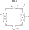
- a rotary compressor (10) is provided in a refrigeration apparatus (1).
- the refrigeration apparatus (1) includes a refrigerant circuit (1a) filled with a refrigerant.
- the refrigerant circuit (1a) includes a rotary compressor (10), a radiator (3), a decompression mechanism (4), and an evaporator (5).
- the decompression mechanism (4) is, for example, an expansion valve.
- the refrigerant circuit (1a) performs a vapor compression refrigeration cycle.
- the refrigeration apparatus (1) is an air conditioner.
- the air conditioner may be any of a cooling-only apparatus, a heating-only apparatus, or an air conditioner switchable between cooling and heating.
- the air conditioner has a switching mechanism (e.g., a four-way switching valve) that switches the direction of circulation of the refrigerant.
- the refrigeration apparatus (1) may be a water heater, a chiller unit, or a cooling apparatus that cools the air in a storage.
- the cooling apparatus cools the air in a refrigerator, a freezer, or a container, for example.
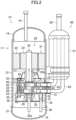
- the rotary compressor (10) includes a casing (11), a drive mechanism (20), and a compression mechanism (30).
- the drive mechanism (20) and the compression mechanism (30) are housed in the casing (11).
- the casing (11) is configured as a vertically long cylindrical closed container.
- the casing (11) includes a barrel (12), a bottom end plate (13), and a top end plate (14).
- the barrel (12) is in the shape of a cylinder extending in the vertical direction, with both axial ends open.
- the bottom end plate (13) is fixed to the lower end of the barrel (12).
- the top end plate (14) is fixed to the upper end of the barrel (12).
- a suction pipe (15) passes through, and is fixed to, the barrel (12).
- a discharge pipe (16) passes through, and is fixed to, the top end plate (14).
- the casing (11) has an oil reservoir (18) at its bottom.
- the oil reservoir (18) is formed by the bottom end plate (13) and an inner wall of a lower portion of the barrel (12).
- the oil reservoir (18) stores oil for lubricating sliding portions of the compression mechanism (30) and a drive shaft (25).
- the drive mechanism (20) includes a motor (21) and a drive shaft (25).
- the motor (21) is disposed above the compression mechanism (30).
- the motor (21) includes a stator (22) and a rotor (23).
- the stator (22) is fixed to the inner peripheral surface of the barrel (12) of the casing (11).
- the rotor (23) extends to penetrate the stator (22) in the vertical direction.
- the drive shaft (25) passes through the axis of the rotor (23) and is fixed to the rotor (23). The drive shaft (25) is driven to rotate together with the rotor (23) when the motor (21) is energized.
- the drive shaft (25) is arranged on the axis of the barrel (12) of the casing (11).
- An oil supply pump (25a) is provided at the lower end of the drive shaft (25).
- the oil supply pump (25a) conveys the oil collected in the oil reservoir (18).
- the conveyed oil is supplied to the sliding portions of the compression mechanism (30) and the drive shaft (25) through an oil passage (25b) in the drive shaft (25).
- the drive shaft (25) includes a main shaft portion (26), a first eccentric portion (27), and a second eccentric portion (28).
- An upper portion of the main shaft portion (26) is fixed to the rotor (23) of the motor (21).
- the first eccentric portion (27) is disposed above the second eccentric portion (28).
- the axes of the first eccentric portion (27) and the second eccentric portion (28) are eccentric from the axis of the main shaft portion (26) by a predetermined amount.
- Part of the main shaft portion (26) above the first eccentric portion (27) is rotatably supported by a front head (31) described later.
- Part of the main shaft portion (26) below the second eccentric portion (28) is rotatably supported by a rear head (33) described later.
- the compression mechanism (30) is a two-cylinder rotary fluid machine.
- the compression mechanism (30) is disposed below the motor (21).
- the compression mechanism (30) includes a front head (31) as a head member, a first cylinder (40), a middle plate (32), a second cylinder (50), and a rear head (33).
- the front head (31), the first cylinder (40), the middle plate (32), the second cylinder (50), and the rear head (33) are stacked in this order from top to bottom and fixed with a fastening bolt (35).
- the front head (31) is fixed to the barrel (12) of the casing (11).
- the front head (31) is stacked on top of the first cylinder (40).
- the front head (31) is arranged to cover a first cylinder chamber (41) of the first cylinder (40) from above.
- the main shaft portion (26) of the drive shaft (25) is inserted in the front head (31) to pass through the center of the front head (31).
- the front head (31) rotatably supports the drive shaft (25).
- the front head (31) has a first discharge passage (49) penetrating the front head (31) in the axial direction (see FIG. 3 ).
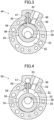
- the first cylinder (40) is configured as a flat, substantially annular member. As illustrated in FIG. 3 , the first cylinder (40) includes a first cylinder chamber (41), a first suction passage (42), and a first blade chamber (43).
- the first cylinder chamber (41) is provided in the center of the first cylinder (40).
- the first suction passage (42) extends from the inner wall surface of the first cylinder chamber (41) toward the outside in the radial direction of the first cylinder (40).
- the first suction passage (42) opens on the outer surface of the first cylinder (40).
- the suction pipe (15) is connected to an inlet end of the first suction passage (42).
- An outlet end of the first suction passage (42) communicates with the first cylinder chamber (41).
- the first cylinder chamber (41) houses a first piston (45).
- the first piston (45) includes a first piston body (46) and a first blade (47).
- the first piston body (46) is formed in an annular shape.
- the first eccentric portion (27) of the drive shaft (25) fits into the first piston body (46).
- the first blade (47) extends radially outward from the first piston body (46).
- the first blade (47) is supported by a pair of first bushes (48).
- the first blade (47) divides the inside of the first cylinder chamber (41) into a low-pressure chamber and a high-pressure chamber.
- the first piston (45) rotates eccentrically in the first cylinder chamber (41) when the drive shaft (25) is driven to rotate.
- the volume of the low-pressure chamber gradually increases with the eccentric rotation of the first piston (45)
- the refrigerant flowing through the suction pipe (15) is sucked through the first suction passage (42) into the low-pressure chamber.
- the isolated space constitutes a high-pressure chamber.
- the internal pressure of the high-pressure chamber increases as the volume of the high-pressure chamber gradually decreases.
- the refrigerant in the high-pressure chamber flows out of the compression mechanism (30) through the first discharge passage (49).
- the high-pressure refrigerant flows upward through the internal space of the casing (11) and passes through a core cut (not shown) of the motor (21) or any other passage.
- the high-pressure refrigerant that has flowed upward of the motor (21) is transferred to the refrigerant circuit through the discharge pipe (16).
- the first blade chamber (43) is located radially outward of the first cylinder chamber (41) and away from the first cylinder chamber (41).
- the first blade chamber (43) penetrates into the first cylinder (40) in the thickness direction of the first cylinder (40).
- a tip portion of the first blade (47) is housed in the first blade chamber (43).
- the first blade (47) swings in the first blade chamber (43) with the eccentric rotation of the first piston body (46).
- the first blade chamber (43) communicates with an oil supply passage (37) described later.
- the middle plate (32) is sandwiched between the first cylinder (40) and the second cylinder (50).
- the middle plate (32) is disposed to cover the first cylinder chamber (41) of the first cylinder (40) from below.
- the middle plate (32) is disposed to cover a second cylinder chamber (51) of the second cylinder (50) from above.
- the second cylinder (50) is configured as a flat, substantially annular member.
- the second cylinder (50) includes the second cylinder chamber (51), a second suction passage (52), and a second blade chamber (53).
- the second cylinder chamber (51) is provided in the center of the second cylinder (50).
- the second suction passage (52) extends from the inner wall surface of the second cylinder chamber (51) toward the outside in the radial direction of the second cylinder (50).
- the second suction passage (52) opens on the outer surface of the second cylinder (50).
- a suction pipe (15) is connected to an inlet end of the second suction passage (52).
- An outlet end of the second suction passage (52) communicates with the second cylinder chamber (51).
- the second cylinder chamber (51) houses a second piston (55).
- the second piston (55) includes a second piston body (56) and a second blade (57).
- the second piston body (56) is formed in an annular shape.
- the second eccentric portion (28) of the drive shaft (25) fits into the second piston body (56).
- the second blade (57) extends radially outward from the second piston body (56).
- the second blade (57) is supported by a pair of second bushes (58).
- the second blade (57) divides the inside of the second cylinder chamber (51) into a low-pressure chamber and a high-pressure chamber.
- the action of the second piston (55) is substantially the same as the action of the first piston (45), and will not be described below.
- the second blade chamber (53) is located radially outward of the second cylinder chamber (51) and away from the second cylinder chamber (51).
- the second blade chamber (53) penetrates into the second cylinder (50) in the thickness direction of the second cylinder (50).
- a tip portion of the second blade (57) is housed in the second blade chamber (53).
- the second blade (57) swings in the second blade chamber (53) with the eccentric rotation of the second piston body (56).
- the second blade chamber (53) communicates with the oil supply passage (37) described later.
- the rear head (33) is stacked on the bottom of the second cylinder (50).
- the rear head (33) is disposed to cover the second cylinder chamber (51) of the second cylinder (50) from below.
- the main shaft portion (26) of the drive shaft (25) is inserted in the rear head (33) to pass through the center of the rear head (33).
- the rear head (33) rotatably supports the drive shaft (25).
- the rear head (33) has a second discharge passage (59) penetrating the rear head (33) in the axial direction (see FIG. 4 ).
- An oil supply siphon pipe (36) is connected to the rear head (33). An upper end of the oil supply siphon pipe (36) is connected to the oil supply passage (37).
- the oil supply passage (37) continuously penetrates the rear head (33), the second cylinder (50), the middle plate (32), and the first cylinder (40).
- the oil supply passage (37) includes the first blade chamber (43) of the first cylinder (40) and the second blade chamber (53) of the second cylinder (50).
- a lower end of the oil supply siphon pipe (36) opens toward the oil reservoir (18).
- the oil supply siphon pipe (36) sucks up the oil in the oil reservoir (18) and supplies the oil to the first blade chamber (43) and the second blade chamber (53) through the oil supply passage (37).
- An accumulator (60) is connected to the upstream side of the rotary compressor (10).
- the accumulator (60) temporarily stores the refrigerant that is to be sucked into the rotary compressor (10) and performs gas-liquid separation for a liquid refrigerant and oil contained in a gas refrigerant.
- the accumulator (60) includes a closed container (61), an inlet pipe (62), and outlet pipes (63).
- the inlet pipe (62) allows the refrigerant to flow into the closed container (61).
- the outlet pipes (63) allow the refrigerant to flow out of the closed container (61).
- the closed container (61) is constituted of a vertically long cylindrical member.
- the inlet pipe (62) is connected to the top of the closed container (61).
- a lower end of the inlet pipe (62) opens in the internal space of the closed container (61) near the top of the closed container (61).
- Each of the outlet pipes (63) has an upper end portion extending upward in the internal space of the closed container (61) and opens near the top of the closed container (61).
- Each of the outlet pipes (63) has a lower end portion that extends downward from the lower end of the closed container (61), bends toward the suction pipe (15) of the rotary compressor (10), and is connected to the suction pipe (15).
- the first blade chamber (43) is divided into two spaces (left and right spaces in FIG. 3 ) by the first blade (47) interposed therebetween.
- the volumes of the two spaces in the first blade chamber (43) vary to cause the oil to flow from one of the spaces (the left space in FIG. 5 ) to the other (the right space in FIG. 5 ).
- a dashed arrow indicates the flow of the oil in the first blade chamber (43).
- the oil is allowed to flow smoothly in the first blade chamber (43) when the first blade (47) swings.
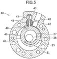
- the rotary compressor (10) includes a loss reducer (70).
- the loss reducer (70) reduces the oil stirring loss in the first blade chamber (43) due to the swing of the first blade (47).
- the loss reducer (70) is a recess (71) formed in the front head (31).
- the recess (71) is provided in the front head (31) at a position facing the first blade chamber (43).
- the oil supply passage (37) supplies the oil to the first blade chamber (43) from a surface of the first cylinder (40) (a lower surface in FIG. 6 ) opposite to a surface on which the front head (31) is stacked.
- the oil in the first blade chamber (43) flows through a clearance between the inner peripheral wall of the first blade chamber (43) and the tip portion of the first blade (47) and through the recess (71) of the front head (31) (see FIG. 7 ).
- This configuration achieves smooth flow of the oil in the first blade chamber (43), and can reduce the oil stirring loss, even in a high-speed rotation range of the first piston (45).
- the number of rotations of the first piston (45) is preferably 118 rps or more.
- the recess (71) provided in the front head (31) can reduce the contact area between the first blade (47) and the front head (31). This reduces a viscous sliding loss of the first blade (47), allowing smooth rotation of the first piston (45).
- D1 is the cross-sectional area of the first blade chamber (43) when viewed in the axial direction of the first cylinder (40)
- D2 is the cross-sectional area of the first blade (47) in the first blade chamber (43) when the first blade (47) reaches the deepest point of the first blade chamber (43) as illustrated in FIG. 8 .
- the cross-sectional area D3 of the recess (71) as viewed in a lateral direction of the front head (31) preferably satisfies D3 ⁇ (D1 - D2) / 2.
- the loss reducer (70) achieves smooth flow of the oil in the blade chamber (43), and can reduce the oil stirring loss, when the blade (47) swings. This allows smooth eccentric rotation of the piston (45).
- the oil in the blade chamber (43) flows through the clearance between the inner peripheral wall of the blade chamber (43) and the tip portion of the blade (47) and through the recess (71) of the head member (31).
- This configuration achieves smooth flow of the oil in the blade chamber (43) and can reduce the oil stirring loss.
- appropriately setting the cross-sectional area of the recess (71) allows smooth flow of the oil in the blade chamber (43).
- increasing the number of rotations of the piston (45) improves the performance of the compressor and can reduce the oil stirring loss even in the high-speed rotation range.
- the refrigeration apparatus includes the rotary compressor (10) and the refrigerant circuit (1a) through which the refrigerant compressed by the rotary compressor (10) flows.
- a refrigeration apparatus including the rotary compressor (10) can thus be provided.
- a rotary compressor (10) includes a loss reducer (70).
- the loss reducer (70) reduces the oil stirring loss in the first blade chamber (43) due to the swing of the first blade (47).
- the loss reducer (70) is configured as a penetrating portion (75) passing through the first blade (47) in the thickness direction of the first blade (47).
- the penetrating portion (75) is a circular hole passing through the tip portion of the first blade (47) in the thickness direction of the first blade (47).
- the oil in the first blade chamber (43) flows through the clearance between the inner peripheral wall of the first blade chamber (43) and the tip portion of the first blade (47) and through the penetrating portion (75) of the first blade (47) in the thickness direction.
- D1 is the cross-sectional area of the first blade chamber (43) when viewed in the axial direction of the first cylinder (40)
- D2 is the cross-sectional area of the first blade (47) in the first blade chamber (43) when the first blade (47) reaches the deepest point of the first blade chamber (43) (see FIG. 8 ).
- the cross-sectional area D4 of the penetrating portion (75) as viewed in the thickness direction of the first blade (47) preferably satisfies D4 ⁇ (D1 - D2) / 2.
- the oil in the blade chamber (43) flows through the clearance between the inner peripheral wall of the blade chamber (43) and the tip portion of the blade (47) and through the penetrating portion (75) of the blade (47).
- This configuration achieves smooth flow of the oil in the blade chamber (43) and can reduce the oil stirring loss.
- appropriately setting the cross-sectional area of the penetrating portion (75) allows smooth flow of the oil in the blade chamber (43).
- a rotary compressor (10) includes a loss reducer (70).
- the loss reducer (70) reduces the oil stirring loss in the first blade chamber (43) due to the swing of the first blade (47).
- the loss reducer (70) is configured as penetrating portions (75) passing through the first blade (47) in the thickness direction of the first blade (47).
- the penetrating portions (75) are formed by cutting out corners of the first blade (47).
- the penetrating portions (75) are provided by cutting the upper right corner of the first blade (47) in FIG. 13 and the lower right corner of the first blade (47) in FIG. 13 .
- the oil in the first blade chamber (43) flows through the clearance between the inner peripheral wall of the first blade chamber (43) and the tip portion of the first blade (47) and through the penetrating portions (75) of the first blade (47) in the thickness direction.
- D1 is the cross-sectional area of the first blade chamber (43) when viewed in the axial direction of the first cylinder (40)
- D2 is the cross-sectional area of the first blade (47) in the first blade chamber (43) when the first blade (47) reaches the deepest point of the first blade chamber (43) (see FIG. 8 ).
- the cross-sectional area D4 of the penetrating portions (75) as viewed in the thickness direction of the first blade (47) preferably satisfies D4 ⁇ (D1 - D2) / 2.
- the cross-sectional area D4 is the sum of the cross-sectional areas of the two penetrating portions (75).
- the oil in the blade chamber (43) flows through the clearance between the inner peripheral wall of the blade chamber (43) and the tip portion of the blade (47) and through the penetrating portions (75) of the blade (47).
- This configuration achieves smooth flow of the oil in the blade chamber (43) and can reduce the oil stirring loss.
- appropriately setting the cross-sectional area of the penetrating portions (75) allows smooth flow of the oil in the blade chamber (43).
- a rotary compressor (10) includes a loss reducer (70).
- the loss reducer (70) reduces the oil stirring loss in the first blade chamber (43) due to the swing of the first blade (47).
- the loss reducer (70) is configured as a penetrating portion (75) passing through the first blade (47) in the thickness direction of the first blade (47).
- the penetrating portion (75) is formed by cutting a rectangular shape out of an axial center part of the tip portion of the first blade (47).
- the oil in the first blade chamber (43) flows through the clearance between the inner peripheral wall of the first blade chamber (43) and the tip portion of the first blade (47) and through the penetrating portion (75) of the first blade (47) in the thickness direction.
- D 1 is the cross-sectional area of the first blade chamber (43) when viewed in the axial direction of the first cylinder (40)
- D2 is the cross-sectional area of the first blade (47) in the first blade chamber (43) when the first blade (47) reaches the deepest point of the first blade chamber (43) (see FIG. 8 ).
- the cross-sectional area D4 of the penetrating portion (75) as viewed in the thickness direction of the first blade (47) preferably satisfies D4 ⁇ (D1 - D2) / 2.
- the oil in the blade chamber (43) flows through the clearance between the inner peripheral wall of the blade chamber (43) and the tip portion of the blade (47) and through the penetrating portion (75) of the blade (47).
- This configuration achieves smooth flow of the oil in the blade chamber (43) and can reduce the oil stirring loss.
- appropriately setting the cross-sectional area of the penetrating portion (75) allows smooth flow of the oil in the blade chamber (43).
- the present disclosure is useful for a rotary compressor and a refrigeration apparatus.
Landscapes
- Engineering & Computer Science (AREA)
- Mechanical Engineering (AREA)
- General Engineering & Computer Science (AREA)
- Applications Or Details Of Rotary Compressors (AREA)
Applications Claiming Priority (2)
| Application Number | Priority Date | Filing Date | Title |
|---|---|---|---|
| JP2023043936A JP7541257B1 (ja) | 2023-03-20 | 2023-03-20 | 回転式圧縮機及び冷凍装置 |
| PCT/JP2024/008355 WO2024195525A1 (ja) | 2023-03-20 | 2024-03-05 | 回転式圧縮機及び冷凍装置 |
Publications (3)
| Publication Number | Publication Date |
|---|---|
| EP4459128A1 true EP4459128A1 (de) | 2024-11-06 |
| EP4459128A4 EP4459128A4 (de) | 2025-04-16 |
| EP4459128B1 EP4459128B1 (de) | 2026-03-25 |
Family
ID=91530141
Family Applications (1)
| Application Number | Title | Priority Date | Filing Date |
|---|---|---|---|
| EP24729953.0A Active EP4459128B1 (de) | 2023-03-20 | 2024-03-05 | Rotationsverdichter und kühlvorrichtung |
Country Status (3)
| Country | Link |
|---|---|
| EP (1) | EP4459128B1 (de) |
| JP (1) | JP7541257B1 (de) |
| WO (1) | WO2024195525A1 (de) |
Family Cites Families (10)
| Publication number | Priority date | Publication date | Assignee | Title |
|---|---|---|---|---|
| JP2876922B2 (ja) * | 1992-11-24 | 1999-03-31 | ダイキン工業株式会社 | ローリングピストン型圧縮機 |
| JPH09112466A (ja) * | 1995-10-23 | 1997-05-02 | Daikin Ind Ltd | スイング圧縮機 |
| JP2000179472A (ja) * | 1998-12-16 | 2000-06-27 | Mitsubishi Electric Corp | ロータリ圧縮機 |
| JP4074760B2 (ja) | 2002-01-10 | 2008-04-09 | 日立アプライアンス株式会社 | 密閉型回転圧縮機及び冷凍・空調装置 |
| WO2006064769A1 (ja) * | 2004-12-13 | 2006-06-22 | Daikin Industries, Ltd. | ロータリ圧縮機 |
| JP2007177634A (ja) | 2005-12-27 | 2007-07-12 | Daikin Ind Ltd | ロータリ圧縮機 |
| JP2010261375A (ja) | 2009-05-08 | 2010-11-18 | Daikin Ind Ltd | ロータリ圧縮機 |
| KR102254378B1 (ko) * | 2019-05-31 | 2021-05-21 | 엘지전자 주식회사 | 로터리 압축기 |
| JP2022072807A (ja) | 2020-10-30 | 2022-05-17 | ダイキン工業株式会社 | 圧縮機、圧縮機の製造方法および空気調和機 |
| JP2023014507A (ja) * | 2021-07-19 | 2023-01-31 | ダイキン工業株式会社 | ロータリ圧縮機 |
-
2023
- 2023-03-20 JP JP2023043936A patent/JP7541257B1/ja active Active
-
2024
- 2024-03-05 EP EP24729953.0A patent/EP4459128B1/de active Active
- 2024-03-05 WO PCT/JP2024/008355 patent/WO2024195525A1/ja not_active Ceased
Also Published As
| Publication number | Publication date |
|---|---|
| JP7541257B1 (ja) | 2024-08-28 |
| JP2024133916A (ja) | 2024-10-03 |
| EP4459128A4 (de) | 2025-04-16 |
| WO2024195525A1 (ja) | 2024-09-26 |
| EP4459128B1 (de) | 2026-03-25 |
Similar Documents
| Publication | Publication Date | Title |
|---|---|---|
| US8985985B2 (en) | Rotary compressor and refrigeration cycle apparatus | |
| US7462021B2 (en) | Rotary compressor, and car air conditioner and heat pump type water heater using the compressor | |
| KR101971819B1 (ko) | 스크롤 압축기 | |
| CN112771323A (zh) | 多级压缩系统 | |
| EP3575605B1 (de) | Hermetischer verdichter | |
| CN103582762B (zh) | 密闭型压缩机和制冷循环装置 | |
| EP4459128A1 (de) | Rotationsverdichter und kühlvorrichtung | |
| CN112771324A (zh) | 多级压缩系统 | |
| EP3636929B1 (de) | Rotationsverdichter | |
| CN114555948B (zh) | 压缩机及冷冻循环装置 | |
| JP2006283592A (ja) | 流体機械 | |
| US11953001B2 (en) | Horizontal type rotary compressor and home appliance including the same | |
| EP4461962A1 (de) | Rotationsverdichter und kühlvorrichtung | |
| EP3388675A1 (de) | Schwingkolbenverdichter | |
| EP4729784A1 (de) | Rotationsverdichter und kühlvorrichtung | |
| JP7727230B1 (ja) | 回転式圧縮機及び冷凍装置 | |
| EP4474651A1 (de) | Rotationsverdichter und kühlvorrichtung | |
| EP4464897A1 (de) | Rotationsverdichter und kühlvorrichtung damit | |
| JP7470567B2 (ja) | 圧縮機及び冷凍サイクル装置 | |
| EP4477888A1 (de) | Verdichter und kühlvorrichtung | |
| EP4707601A1 (de) | Rotationsverdichter und kühlvorrichtung | |
| JP2026060594A (ja) | ロータリ圧縮機及び冷凍装置 | |
| JP5181463B2 (ja) | 流体機械 | |
| JP2026061701A (ja) | ロータリ圧縮機 |
Legal Events
| Date | Code | Title | Description |
|---|---|---|---|
| STAA | Information on the status of an ep patent application or granted ep patent |
Free format text: STATUS: UNKNOWN |
|
| STAA | Information on the status of an ep patent application or granted ep patent |
Free format text: STATUS: THE INTERNATIONAL PUBLICATION HAS BEEN MADE |
|
| PUAI | Public reference made under article 153(3) epc to a published international application that has entered the european phase |
Free format text: ORIGINAL CODE: 0009012 |
|
| STAA | Information on the status of an ep patent application or granted ep patent |
Free format text: STATUS: REQUEST FOR EXAMINATION WAS MADE |
|
| 17P | Request for examination filed |
Effective date: 20240610 |
|
| AK | Designated contracting states |
Kind code of ref document: A1 Designated state(s): AL AT BE BG CH CY CZ DE DK EE ES FI FR GB GR HR HU IE IS IT LI LT LU LV MC ME MK MT NL NO PL PT RO RS SE SI SK SM TR |
|
| RIN1 | Information on inventor provided before grant (corrected) |
Inventor name: UENO, HIROMICHI |
|
| P01 | Opt-out of the competence of the unified patent court (upc) registered |
Free format text: CASE NUMBER: APP_982/2025 Effective date: 20250108 |
|
| A4 | Supplementary search report drawn up and despatched |
Effective date: 20250318 |
|
| RIC1 | Information provided on ipc code assigned before grant |
Ipc: F04C 18/356 20060101ALI20250312BHEP Ipc: F04C 23/00 20060101ALI20250312BHEP Ipc: F04C 29/02 20060101ALI20250312BHEP Ipc: F04C 18/46 20060101ALI20250312BHEP Ipc: F01C 21/08 20060101ALI20250312BHEP Ipc: F04C 29/00 20060101AFI20250312BHEP |
|
| GRAP | Despatch of communication of intention to grant a patent |
Free format text: ORIGINAL CODE: EPIDOSNIGR1 |
|
| STAA | Information on the status of an ep patent application or granted ep patent |
Free format text: STATUS: GRANT OF PATENT IS INTENDED |
|
| RIC1 | Information provided on ipc code assigned before grant |
Ipc: F04C 29/00 20060101AFI20251029BHEP Ipc: F01C 21/08 20060101ALI20251029BHEP Ipc: F04C 18/46 20060101ALI20251029BHEP Ipc: F04C 29/02 20060101ALI20251029BHEP Ipc: F04C 23/00 20060101ALI20251029BHEP Ipc: F04C 18/356 20060101ALI20251029BHEP |
|
| DAV | Request for validation of the european patent (deleted) | ||
| DAX | Request for extension of the european patent (deleted) | ||
| INTG | Intention to grant announced |
Effective date: 20251113 |
|
| GRAS | Grant fee paid |
Free format text: ORIGINAL CODE: EPIDOSNIGR3 |
|
| GRAA | (expected) grant |
Free format text: ORIGINAL CODE: 0009210 |
|
| STAA | Information on the status of an ep patent application or granted ep patent |
Free format text: STATUS: THE PATENT HAS BEEN GRANTED |
|
| AK | Designated contracting states |
Kind code of ref document: B1 Designated state(s): AL AT BE BG CH CY CZ DE DK EE ES FI FR GB GR HR HU IE IS IT LI LT LU LV MC ME MK MT NL NO PL PT RO RS SE SI SK SM TR |
|
| REG | Reference to a national code |
Ref country code: CH Ref legal event code: F10 Free format text: ST27 STATUS EVENT CODE: U-0-0-F10-F00 (AS PROVIDED BY THE NATIONAL OFFICE) Effective date: 20260325 Ref country code: GB Ref legal event code: FG4D |
|
| REG | Reference to a national code |
Ref country code: DE Ref legal event code: R096 Ref document number: 602024003468 Country of ref document: DE |
|
| REG | Reference to a national code |
Ref country code: IE Ref legal event code: FG4D |