EP4459149A1 - Embrayage électromagnétique et procédé de fermeture et d'ouverture d'un embrayage électromagnétique - Google Patents
Embrayage électromagnétique et procédé de fermeture et d'ouverture d'un embrayage électromagnétique Download PDFInfo
- Publication number
- EP4459149A1 EP4459149A1 EP24167142.9A EP24167142A EP4459149A1 EP 4459149 A1 EP4459149 A1 EP 4459149A1 EP 24167142 A EP24167142 A EP 24167142A EP 4459149 A1 EP4459149 A1 EP 4459149A1
- Authority
- EP
- European Patent Office
- Prior art keywords
- shift sleeve
- armature
- shaft
- toothing
- state
- Prior art date
- Legal status (The legal status is an assumption and is not a legal conclusion. Google has not performed a legal analysis and makes no representation as to the accuracy of the status listed.)
- Granted
Links
Images




Classifications
-
- F—MECHANICAL ENGINEERING; LIGHTING; HEATING; WEAPONS; BLASTING
- F16—ENGINEERING ELEMENTS AND UNITS; GENERAL MEASURES FOR PRODUCING AND MAINTAINING EFFECTIVE FUNCTIONING OF MACHINES OR INSTALLATIONS; THERMAL INSULATION IN GENERAL
- F16D—COUPLINGS FOR TRANSMITTING ROTATION; CLUTCHES; BRAKES
- F16D27/00—Magnetically- or electrically- actuated clutches; Control or electric circuits therefor
- F16D27/02—Magnetically- or electrically- actuated clutches; Control or electric circuits therefor with electromagnets incorporated in the clutch, i.e. with collecting rings
- F16D27/09—Magnetically- or electrically- actuated clutches; Control or electric circuits therefor with electromagnets incorporated in the clutch, i.e. with collecting rings and with interengaging jaws or gear-teeth
-
- F—MECHANICAL ENGINEERING; LIGHTING; HEATING; WEAPONS; BLASTING
- F16—ENGINEERING ELEMENTS AND UNITS; GENERAL MEASURES FOR PRODUCING AND MAINTAINING EFFECTIVE FUNCTIONING OF MACHINES OR INSTALLATIONS; THERMAL INSULATION IN GENERAL
- F16D—COUPLINGS FOR TRANSMITTING ROTATION; CLUTCHES; BRAKES
- F16D27/00—Magnetically- or electrically- actuated clutches; Control or electric circuits therefor
- F16D27/14—Details
-
- F—MECHANICAL ENGINEERING; LIGHTING; HEATING; WEAPONS; BLASTING
- F16—ENGINEERING ELEMENTS AND UNITS; GENERAL MEASURES FOR PRODUCING AND MAINTAINING EFFECTIVE FUNCTIONING OF MACHINES OR INSTALLATIONS; THERMAL INSULATION IN GENERAL
- F16D—COUPLINGS FOR TRANSMITTING ROTATION; CLUTCHES; BRAKES
- F16D27/00—Magnetically- or electrically- actuated clutches; Control or electric circuits therefor
- F16D27/10—Magnetically- or electrically- actuated clutches; Control or electric circuits therefor with an electromagnet not rotating with a clutching member, i.e. without collecting rings
- F16D27/118—Magnetically- or electrically- actuated clutches; Control or electric circuits therefor with an electromagnet not rotating with a clutching member, i.e. without collecting rings with interengaging jaws or gear teeth
-
- F—MECHANICAL ENGINEERING; LIGHTING; HEATING; WEAPONS; BLASTING
- F16—ENGINEERING ELEMENTS AND UNITS; GENERAL MEASURES FOR PRODUCING AND MAINTAINING EFFECTIVE FUNCTIONING OF MACHINES OR INSTALLATIONS; THERMAL INSULATION IN GENERAL
- F16D—COUPLINGS FOR TRANSMITTING ROTATION; CLUTCHES; BRAKES
- F16D11/00—Clutches in which the members have interengaging parts
- F16D2011/008—Clutches in which the members have interengaging parts characterised by the form of the teeth forming the inter-engaging parts; Details of shape or structure of these teeth
-
- F—MECHANICAL ENGINEERING; LIGHTING; HEATING; WEAPONS; BLASTING
- F16—ENGINEERING ELEMENTS AND UNITS; GENERAL MEASURES FOR PRODUCING AND MAINTAINING EFFECTIVE FUNCTIONING OF MACHINES OR INSTALLATIONS; THERMAL INSULATION IN GENERAL
- F16D—COUPLINGS FOR TRANSMITTING ROTATION; CLUTCHES; BRAKES
- F16D27/00—Magnetically- or electrically- actuated clutches; Control or electric circuits therefor
- F16D2027/007—Bias of an armature of an electromagnetic clutch by flexing of substantially flat springs, e.g. leaf springs
Definitions
- the invention relates to an electromagnetic clutch and a method for closing and opening an electromagnetic clutch.
- electromagnetic clutch refers to the fact that the clutch is operated electromagnetically. However, the torque transmission when the clutch is closed can be positive and/or frictional.
- Movable coupling sleeves are often used for positive-locking couplings. These have one or more different gear teeth that engage with counter gear teeth, creating a positive connection that can be used to transfer torque from one shaft to another.
- Electromagnetic clutches are known from the state of the art in which the adjustment of the sliding clutch sleeve is carried out via a coil that exerts a magnetic force on the clutch sleeve.
- the switching path along which the sliding clutch sleeve can be adjusted by the magnetic forces is limited. This is due to the fact that the magnetic forces that can be applied to the clutch sleeve decrease with increasing distance from the coil. This means that the switching sleeve can only be adjusted along a certain section via the magnetic force of the coil and thus the axial overlap of the teeth and counter teeth is also correspondingly limited.
- the disadvantage is that the use of larger coils increases the installation space required and the material costs.
- the use of larger coils also increases the weight of the electromagnetic clutch. This has a particularly negative effect when the electromagnetic clutch is used in vehicles.
- the object of the invention is to provide an electromagnetic clutch in which the greatest possible axial overlap of the gear teeth can be achieved despite the limited magnetic switching path of the shift sleeve. This is to be achieved without using a larger coil and without significantly increasing the weight of the electromagnetic clutch.
- an electromagnetic clutch with a shift sleeve which has a first toothing which is arranged in a rotationally fixed manner on a first shaft and is adjustable linearly along the shaft between an engaged and disengaged state, a first clutch body which has a second toothing and which is aligned coaxially to the first shaft, a stator which comprises a first coil which serves for the direct or indirect adjustment of the shift sleeve linearly along the shaft, wherein the first and/or second toothing has/have undercuts in the direction of the engaged state which are designed in such a way that a torque transmission between the shaft and the first clutch body generates a force on the shift sleeve in the direction of the engaged state, and wherein in the engaged state there is a positive connection between the shift sleeve and the first clutch body through the first and second toothing.
- the basic idea of the invention is that the shift sleeve can be adjusted from the disengaged state to the engaged state by means of the first coil, thus creating a positive connection between the first and second gear teeth, since there is already a reduced axial overlap of the gear teeth in the axial direction.
- the first and/or second teeth If torque is transmitted between the first shaft and the clutch body, the first and/or second teeth generate a force due to the undercuts, which acts on the shift sleeve in the direction of the engagement state.
- the additional displacement of the shift sleeve during torque transmission is accompanied by an increase in the axial overlap of the first and second gear teeth, so that higher torques can be transmitted.
- the total switching path of the shift sleeve is thus divided into a first switching path, which is carried out by means of the coil, and a second switching path, which is caused by the undercuts of the first and/or second gearing in conjunction with an acting torque.
- This design allows a simple structure to accommodate longer switching travels and a larger axial overlap of the gears without changing the dimensioning of the coil or increasing the air gap between the armature and stator.
- the first coil serves for the direct or indirect adjustment of the shift sleeve linearly along the first shaft into the engaged state and that the stator comprises a second coil which serves for the direct or indirect adjustment of the shift sleeve linearly along the first shaft against the engaged state.
- a spring return can be provided in the second coil, which applies a spring force to the shift sleeve linearly along the first shaft against the engaged state.
- both coils serve to adjust the shift sleeve into the clutch-engaging and clutch-disengaging state.
- the additional displacement of the shift sleeve toward the engaged state increases the axial overlap of the first and second gear teeth, which is greater than if the shift sleeve is adjusted to the engaged state solely by the coil.
- the first and/or second toothing provided with undercuts can have teeth whose tooth flanks, in plan view, run in a wedge shape at least along a section of the tooth.
- the wedge shape allows for a simple design of the undercuts and still ensures that the teeth of the gears are supported on one another, provided that the tooth flanks of the teeth are coordinated with one another.
- the first and second toothings have undercuts, wherein the tapered ends of the wedge-shaped sections of the first and second toothings run in opposite directions.
- both gears have wedge-shaped sections
- the tooth flanks of the gears can be matched to each other so that the wedge-shaped sections are present in a flat manner.
- an armature can be provided which is coupled to the shift sleeve and is adjustable along the first shaft by energizing the first and/or second coil, wherein the armature and the shift sleeve are coupled to one another so as to be displaceable in the axial direction.
- the material for the shift sleeve can be selected and treated independently of its magnetic properties.
- torque-transmitting components can be hardened without having to take the magnetic properties of the shift sleeve into account.
- all torque-transmitting components can also be magnetically decoupled from the armature.
- this design allows for extremely small gaps between the armature and the stator, which enables particularly high switching forces to be achieved.
- the adjustment of the armature by at least one of the coils can be limited by a stop, which is provided in particular on the coupling body in order to avoid contact with the stator, wherein when the armature rests against the stop when the coil is energized, a magnetic holding force can be present which acts on the armature.
- the armature and the shift sleeve are coupled in the axial direction via at least one elastic spring unit, which compresses upon axial relative displacement of the shift sleeve and the armature to one another.
- the spring unit allows a relative movement between the shift sleeve and the armature. At the same time, it compresses, creating a spring force that pushes the shift sleeve and the armature back to their original relative position.
- At least one spring unit can be arranged such that when the first and second gear teeth contact each other at the front and when the shift sleeve is not yet coupled to the first clutch body, the spring unit preloads the shift sleeve in the direction of the engagement state.
- the armature can have a first axial contact surface and the shift sleeve can have a second axial contact surface and the elastic spring unit can be supported in the axial direction on the first and second axial contact surfaces.
- the anchor can have a radial web on which the first axial contact surface is provided.
- a web offers a particularly simple implementation for a contact surface and is also stable.
- the first spring unit can be provided on one axial side of the web and a second spring unit on the opposite side of the web, wherein at least one of the spring units exerts a restoring force upon relative displacement of the armature and the shift sleeve.
- the elastic spring units still allow a relative displacement between the armature and the shift sleeve.
- the restoring forces caused by at least one of the spring units cause the shift sleeve to move back to its initial state relative to the armature.
- the spring units can be accommodated in spaces which are delimited radially on the inside by a shift sleeve and radially on the outside by an anchor as well as on one end face by the web and on the opposite end face by a gearwheel which is firmly connected to the shift sleeve, wherein the gearwheel has the first toothing and, in the engaged state, engages in the second toothing provided on the clutch body.
- the at least one spring unit is at least one shaft ring or one disc spring or comprises a package of these.
- Both disc springs and wave springs are particularly suitable because they act evenly along the entire circumference on the two axial contact surfaces when they are preloaded or compressed.
- At least one spring unit can be arranged in such a way that, when the shift sleeve is not yet coupled to the clutch body, this spring unit is pre-tensioned in order to exert a spring force on the shift sleeve in the direction of the engaged state. If necessary, the spring unit can pre-tension the shift sleeve in the direction of the engaged state when the teeth abut head to head. The displacement force is transferred from the armature to the shift sleeve via the spring unit and the spring unit compresses when there is sufficient resistance from the shift sleeve so that the spring unit then permanently presses against the shift sleeve in the direction of the engaged state. When the teeth initially abut head to head, the spring unit presses the shift sleeve into the teeth on the clutch body as soon as a tooth gap is reached.
- the at least one spring unit can be arranged such that when the shift sleeve is coupled to the first clutch body, this spring unit is pre-tensioned in order to exert a spring force on the shift sleeve in the direction of the disengaging state. This means that the shift sleeve is pre-tensioned in the direction of the disengaging state.
- the spring force therefore permanently supports the disengaging process, even if the armature has not yet been moved.
- a spring detent can be provided which serves to exert a holding force on the shift sleeve in the coupling and/or disengaging state.
- this also makes it possible that when the armature together with the shift sleeve is moved towards the engagement state, the spring detent exerts a holding force on the shift sleeve in the engagement state as soon as the armature has reached the stop, or as soon as the shift sleeve is additionally moved further towards the engagement state by a torque load.
- a second coupling body may be provided which is aligned coaxially with the first shaft and is provided on the axial side of the shift sleeve opposite the first coupling body, and with the Shift sleeve can be coupled via actuation of the second coil, wherein the toothing of the second coupling body and the associated toothing of the shift sleeve are designed like the toothing of the first coupling body and its associated toothing.
- the spring units can act on the shift sleeve before and after engagement in the direction of the engagement state or the disengagement state, as already explained above.
- the first coil is therefore energized first, so that the armature moves the shift sleeve from the disengaged state to the engaged state.
- the coupling between the armature and the shift sleeve is achieved via spring units, which are preferably pre-tensioned by the movement of the armature, so that the displacement of the armature is accompanied by a practically direct displacement of the shift sleeve.
- first and second teeth lie on top of each other and the teeth of the shift sleeve do not engage directly with the teeth of the clutch body.
- the shift sleeve If the shift sleeve is twisted relative to the clutch body, the shift sleeve will move into the engaged state at an accelerated rate due to the pre-tensioned spring and form a positive connection with the clutch body.
- the teeth have a first axial overlap with each other.
- This positive locking allows the transmission of torque between the clutch body and the first shaft, which results in the shift sleeve moving further towards the clutch body relative to the armature and the axial overlap of the gears increasing so that additional torque can be transmitted.
- the shift sleeve is therefore still in the engaged state. However, the overlap of the teeth decreases to the original overlap.
- the magnetic force acting through the first coil must first be reduced or eliminated.
- the second coil must be energized so that a magnetic force acts towards the disengaged state, which moves the armature and the shift sleeve axially along the first shaft.
- Figure 1 shows an electromagnetic clutch 10 which serves to couple a first shaft 12 and a second shaft 14 aligned coaxially with the first shaft 12 by opening and closing.
- the electromagnetic clutch 10 comprises a shift sleeve 16, which has a shift sleeve sleeve 17 and a first toothing 18.
- the toothing 18 radially outside of the circumference is provided on a gear 19 which is connected in a rotationally fixed manner to the shift sleeve 17.
- the shift sleeve 16 can also be designed in one piece.
- the shift sleeve 16 is arranged in a rotationally fixed manner on the first shaft 12 and is linearly adjustable along the shaft between an engaged and a disengaged state.
- Figure 1 shows the shift sleeve 16 in the disengaged state.
- a first coupling body 20 is assigned to the second shaft 14.
- the coupling body 20 has a second toothing 22, here an internal toothing, and is coupled in a rotationally fixed manner to the second shaft 14, so that the coupling body 20 is aligned coaxially to the first shaft 12.
- first coupling body 20 forms part of the second shaft 14 and is formed integrally therewith.
- the coupling body 20 comprises at least one annular portion and the second toothing 22 runs along the radial inner side of the annular portion.
- the first and second teeth 18, 22 of the shift sleeve 16 and the first clutch body 20 are positioned at the ends of the shafts 12, 14.
- both the first and the second gear teeth 18, 22 have undercuts 23 and 25 respectively when viewed in the axial direction.
- the first and second teeth 18, 22 serve to form a positive connection between the shift sleeve 16 and the first clutch body 20 when the shift sleeve 16 is in the engaged state.
- a stator 24 which comprises a first coil 26 and a second coil 28.
- the first coil 26 serves to adjust the shift sleeve 16 linearly along the first shaft 12 into the clutch-engaging state (in Figure 1 to the left) and the second coil 28 for adjusting the shift sleeve 16 linearly along the first shaft 12 against the engagement state, i.e. away from the first clutch body 20.
- a spring may also be provided (not shown in the figures) which applies a spring force to the shift sleeve 16 linearly along the first shaft 12 against the engagement state.
- the adjustment of the shift sleeve 16 by the first and second coils 26, 28 can be carried out directly by the coils 26, 28 exerting a magnetic force directly on the shift sleeve 16 itself.
- an armature 30 can also be provided which is coupled to the shift sleeve 16 in the axial direction.
- the adjustment of the shift sleeve 16 takes place indirectly via the armature 30.
- the armature 30 is therefore adjustable by energizing the first or second coil 26, 28 along the first shaft 12 and can take the shift sleeve 16 with it.
- the armature 30 can be magnetically decoupled from the shift sleeve 16.
- a stop 32 can be provided which is provided on the first coupling body 20 and limits the adjustment of the armature 30 by the first coil 26 in the direction of the first coupling body 20.
- first elastic spring unit 34 and a second elastic spring unit 36 are provided, via which the armature 30 and the shift sleeve 16 are coupled to one another so as to be displaceable in the axial direction.
- the elastic spring units 34, 36 are arranged between the armature 30 and the shift sleeve 16 in such a way that a relative displacement in the axial direction results in at least the compression of one of the spring units 34, 36.
- the first elastic spring unit 34 and the second elastic spring unit 36 are housed in spaces 38, 40.
- Both of the spaces 38, 40 are delimited radially on the inside by the shift sleeve 17. Radially on the outside, the two spaces 38, 40 are defined by the armature 30.
- the space 38 for the spring unit 34 is delimited by a first axial contact surface 42, which is provided on a radial web 44 of the armature 30. Furthermore, the space 38 is delimited on the side opposite the first axial contact surface 42 by a second axial contact surface 46.
- the second axial contact surface 46 is provided on the front side of the gear 19.
- the first elastic spring unit 34 is supported in the axial direction on the first axial contact surface 42 and the second axial contact surface 46 and can optionally be preloaded between the axial contact surfaces 42, 46.
- the space 40 is defined by a third axial contact surface 48, which is provided on the side of the web 44 opposite the second axial contact surface 46, and a fourth axial contact surface 50, which is provided on the shift sleeve 16.
- the second elastic spring unit 36 is supported in the axial direction on the third axial contact surface 48 and the fourth axial contact surface 50. Optionally, this can also be pre-tensioned between the contact surfaces 48, 50.
- Both of the spring units 34, 36 each comprise at least one shaft ring. Alternatively, they can each comprise a package of several shaft rings.
- each of the spring units 34, 36 comprises a disc spring or a disc spring package.
- the electromagnetic clutch 10 can comprise a spring detent 52 having a spring ring 54 that is guided within a groove 56 provided on the first shaft 12 and can engage in recesses 58 provided on the shift sleeve 16, so that the spring detent 52 exerts a holding force on the shift sleeve 16 in the disengaged state.
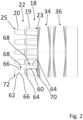
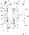
- Figure 2 the first and second gearing 18, 22 provided with undercuts 23, 25 in detail.
- the first gearing has teeth 60 and the second gearing 22 has teeth 62.
- the respective undercuts 23, 25 of the gear teeth 18, 22 are formed by the wedge-shaped tooth flanks 64 of the teeth 60 and the wedge-shaped tooth flanks 66 of the teeth 62, whereby wedge-shaped sections 68, i.e. gaps, are formed.
- the wedge-shaped sections 68 correspond only to a part of the entire tooth flank.
- the teeth 60 Due to the wedge-shaped tooth flanks 64, the teeth 60 have tapered ends 70 and the teeth 62 have tapered ends 72 due to the wedge-shaped tooth flanks 66.
- the tapered ends 70 extend in an opposite direction to the tapered ends 72, so that the ends 70, 72 point in opposite directions.
- the tapered ends 70 are arranged on the side of the wedge-shaped section 68 of the first toothing 18 facing away from the clutch body 20 and the tapered ends 72 are arranged on the side of the wedge-shaped section 68 of the second toothing 22 facing away from the shift sleeve 16.
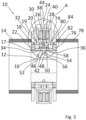
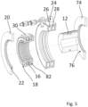
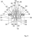
- the Figures 3 to 10 show the electromagnetic clutch 10 according to a second option.
- the electromagnetic clutch 10 according to the second option additionally comprises a second clutch body 74 which is aligned coaxially with the first shaft 12 and is arranged on a third shaft 78.
- the second coupling body 74 has a third toothing 76.
- the second clutch body 74 can also be provided as an independent component on the third shaft 78 or can be designed as a single piece therewith.
- a second gear 80 is arranged on the side of the shift sleeve 16 facing the second clutch body 74, the end face of which facing the web 44 forms the fourth axial contact surface 50.
- the second gear 80 is provided with a fourth toothing 82.
- the shift sleeve 16 can be adjusted directly or indirectly via the armature 30 by means of the second coil 28 towards the second clutch body 74 into a clutch-engaging state in which a positive connection is formed by the third toothing 76 and the fourth toothing 82 between the third shaft 78 and the shift sleeve 16.
- a stop 84 is provided on the second coupling body 74, which limits an adjustment of the armature 30.
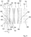
- the third and fourth toothings 76, 82 have teeth 86, 88 which are designed analogously to those of the first and second toothings 18, 22 and also have undercuts. Consequently, the third and fourth toothings 76, 82 have wedge-shaped sections 90.
- the function of the electromagnetic clutch is described exclusively by coupling the shift sleeve 16 with the first clutch body 20. However, the explanations can also be applied equally to coupling the shift sleeve 16 with the second clutch body 74.
- the initial state is the disengaging state of the shift sleeve 16, as shown in the Figures 4 and 6 shown.
- the spring detent 52 exerts a holding force on the shift sleeve in the disengaged state.
- the shift sleeve 16 can exert a holding force in the disengaged state via the armature 30, to which the shift sleeve is coupled via the elastic spring units 34, 36.
- Applying voltage to the first coil 26 creates a magnetic flux through which a magnetic force acts on the armature 30 in the direction of the first clutch body 20.
- the magnetic force displaces the armature 30, which in turn is coupled to the shift sleeve 16 via the first and second elastic spring units 34, 36.
- a displacement of the armature 30 with pre-tensioned elastic spring units 34, 36 immediately results in the shift sleeve 16 being moved along.
- At least one of the spring units 34, 36 must first be compressed so that a spring force builds up.
- the spring force that builds up acts on the shift sleeve 16 so that the shift sleeve 16 is indirectly carried along by the armature 30 via the spring unit as soon as the amount of the spring force exceeds the amount of any holding force that may be acting.
- the first toothing 18 of the shift sleeve 16 can either, as shown in the Figures 7 and 8 shown, before reaching the stop 32 already directly engages the second toothing 22 of the first coupling body 20, so that a positive connection is formed.
- first and second toothings 18, 22 may also first come into contact at the front before the stop 32 is reached.
- the toothings 18, 22 are tooth on tooth, and further axial displacement of the shift sleeve 16 towards the first clutch body 20 is prevented.
- the space 40 increases in the axial direction, so that the third and fourth axial contact surfaces 48, 50 move away from each other.
- a frontal contact of the first and second toothing 18, 22 therefore has an additional preloading of the first elastic spring unit 34 for result, so that an additional spring force acts on the shift sleeve 16 towards the first clutch body 20.
- the force acting on the shift sleeve 16 depends largely on the geometry of the undercuts 23, 25 and the existing torque.
- the force acting on the shift sleeve 16 increases in such a way that the shift sleeve 16 is thereby moved relative to the armature 30 located at the stop 32 towards the first clutch body 20, so that the axial overlap of the first and second gearing 18, 22 increases further until a second axial overlap U 2 is reached, which corresponds to a maximum axial overlap and exceeds the amount of the first axial overlap U 1 .
- the space 38 increases in the axial direction, so that first the elastic spring unit 34 relaxes in the axial direction (assuming it was previously in a pre-tensioned state).
- the space 40 is reduced in the axial direction, whereby the second elastic spring unit 36 between the third axial contact surface 48 of the web 44 and the fourth axial contact surface 50 of the second gear 80.
- the shift sleeve 16 is displaced away from the first clutch body 20 at least from a certain threshold value of the torque due to the spring force acting on the shift sleeve 16 through the strongly compressed second elastic spring unit 36, so that the first and second toothing 18, 22 again assume the first axial overlap U 1 , as shown in the Figures 7 and 8 shown.
- the shift sleeve can again be held in accordance with the above explanations by the spring detent 52 and/or via the armature 30 by energizing the first and second coils 26, 28.
Landscapes
- Engineering & Computer Science (AREA)
- General Engineering & Computer Science (AREA)
- Mechanical Engineering (AREA)
- Physics & Mathematics (AREA)
- Electromagnetism (AREA)
- Mechanical Operated Clutches (AREA)
Applications Claiming Priority (1)
| Application Number | Priority Date | Filing Date | Title |
|---|---|---|---|
| DE102023109684.2A DE102023109684A1 (de) | 2023-04-18 | 2023-04-18 | Elektromagnetische Kupplung und Verfahren zum Schließen und Öffnen einer elektromagnetischen Kupplung |
Publications (2)
| Publication Number | Publication Date |
|---|---|
| EP4459149A1 true EP4459149A1 (fr) | 2024-11-06 |
| EP4459149B1 EP4459149B1 (fr) | 2026-03-18 |
Family
ID=90544952
Family Applications (1)
| Application Number | Title | Priority Date | Filing Date |
|---|---|---|---|
| EP24167142.9A Active EP4459149B1 (fr) | 2023-04-18 | 2024-03-28 | Embrayage électromagnétique et procédé de fermeture et d'ouverture d'un embrayage électromagnétique |
Country Status (4)
| Country | Link |
|---|---|
| US (1) | US12516703B2 (fr) |
| EP (1) | EP4459149B1 (fr) |
| CN (1) | CN118815840A (fr) |
| DE (1) | DE102023109684A1 (fr) |
Families Citing this family (2)
| Publication number | Priority date | Publication date | Assignee | Title |
|---|---|---|---|---|
| DE102023128458A1 (de) * | 2023-10-17 | 2025-04-17 | Hoerbiger Antriebstechnik Holding Gmbh | Elektromagnetisch betätigte Klauenkupplung und Verfahren zur Montage einer Schaltmuffe einer elektromagnetisch betätigten Klauenkupplung |
| DE102023128799A1 (de) | 2023-10-19 | 2025-04-24 | Hoerbiger Antriebstechnik Holding Gmbh | Elektromagnetische Kupplung und Verfahren zum Betätigen einer elektromagnetischen Kupplung |
Citations (4)
| Publication number | Priority date | Publication date | Assignee | Title |
|---|---|---|---|---|
| US2969134A (en) * | 1955-06-03 | 1961-01-24 | Ite Circuit Breaker Ltd | Solenoid operated positive drive clutch |
| US9816569B2 (en) * | 2013-03-22 | 2017-11-14 | Toyota Jidosha Kabushiki Kaisha | Engagement device and power transmission device |
| DE102017204113A1 (de) * | 2017-03-13 | 2018-09-13 | Zf Friedrichshafen Ag | Kupplungsvorrichtung mit einer ersten, formschlüssig wirkenden Kupplung und mit einer zweiten, durch ein viskositätsveränderliches Wirkmedium wirkenden Kupplung |
| US20210190150A1 (en) * | 2017-11-22 | 2021-06-24 | Schaeffler Technologies AG & Co. KG | Clutch unit for a powertrain with an interlocking clutch, and hybrid module with a clutch unit acting as a disconnect clutch |
Family Cites Families (4)
| Publication number | Priority date | Publication date | Assignee | Title |
|---|---|---|---|---|
| US2535388A (en) * | 1947-01-22 | 1950-12-26 | Caterpillar Tractor Co | Transmission coupling device |
| JPH09196128A (ja) * | 1996-01-23 | 1997-07-29 | Seiko Epson Corp | 電気自動車の変速駆動装置及び変速駆動方法 |
| DE102021124595A1 (de) * | 2021-09-22 | 2023-03-23 | Hoerbiger Antriebstechnik Holding Gmbh | Kupplungsvorrichtung sowie Verfahren zum Betrieb einer Kupplungsvorrichtung |
| DE102023112192A1 (de) * | 2023-05-09 | 2024-11-14 | Hoerbiger Antriebstechnik Holding Gmbh | Elektromechanische Kupplung mit Schaltmuffe |
-
2023
- 2023-04-18 DE DE102023109684.2A patent/DE102023109684A1/de active Pending
-
2024
- 2024-03-28 EP EP24167142.9A patent/EP4459149B1/fr active Active
- 2024-04-18 CN CN202410468525.1A patent/CN118815840A/zh active Pending
- 2024-04-18 US US18/639,231 patent/US12516703B2/en active Active
Patent Citations (4)
| Publication number | Priority date | Publication date | Assignee | Title |
|---|---|---|---|---|
| US2969134A (en) * | 1955-06-03 | 1961-01-24 | Ite Circuit Breaker Ltd | Solenoid operated positive drive clutch |
| US9816569B2 (en) * | 2013-03-22 | 2017-11-14 | Toyota Jidosha Kabushiki Kaisha | Engagement device and power transmission device |
| DE102017204113A1 (de) * | 2017-03-13 | 2018-09-13 | Zf Friedrichshafen Ag | Kupplungsvorrichtung mit einer ersten, formschlüssig wirkenden Kupplung und mit einer zweiten, durch ein viskositätsveränderliches Wirkmedium wirkenden Kupplung |
| US20210190150A1 (en) * | 2017-11-22 | 2021-06-24 | Schaeffler Technologies AG & Co. KG | Clutch unit for a powertrain with an interlocking clutch, and hybrid module with a clutch unit acting as a disconnect clutch |
Also Published As
| Publication number | Publication date |
|---|---|
| US12516703B2 (en) | 2026-01-06 |
| EP4459149B1 (fr) | 2026-03-18 |
| CN118815840A (zh) | 2024-10-22 |
| US20240352979A1 (en) | 2024-10-24 |
| DE102023109684A1 (de) | 2024-10-24 |
Similar Documents
| Publication | Publication Date | Title |
|---|---|---|
| DE102010028281B4 (de) | Parksperreneinrichtung für ein Kraftfahrzeug-Automatgetriebe | |
| EP4459149B1 (fr) | Embrayage électromagnétique et procédé de fermeture et d'ouverture d'un embrayage électromagnétique | |
| WO2020182630A1 (fr) | Crabot servant à assembler par complémentarité de forme un premier composant rotatif à un deuxième composant rotatif | |
| DE102021112205A1 (de) | Betätigungsvorrichtung für zwei Kupplungen sowie Hybridgetriebe und Doppelkupplungsgetriebe | |
| EP2882974B1 (fr) | Élément d'actionnement compensateur d'usure pour embrayage | |
| DE102008026902A1 (de) | Axialverstellvorrichtung mit Linearantriebsmitteln | |
| DE102015201854A1 (de) | Elektromagnetische Kupplung zur drehfesten Verbindung von zwei relativ zueinander drehbaren Wellen | |
| DE102016215148A1 (de) | Betätigungseinrichtung für eine Reibungskupplung, Kupplungsanordnung sowie Kraftfahrzeugantriebsstrang | |
| EP3477157A1 (fr) | Blocage du différentiel | |
| EP3293417A1 (fr) | Dispositif d'entraînement en rotation pourvu de frein asservi à la charge | |
| EP4461984A1 (fr) | Embrayage électromagnétique avec manchon de commande | |
| AT7699U1 (de) | Klauenkupplung und differentialsperre mit einer solchen | |
| DE102005040485B4 (de) | Schalteinrichtung für ein Schaltgetriebe und Verfahren zur Herstellung einer derartigen Schalteinrichtung | |
| DE602004010619T2 (de) | Verfahren zur montage eines halterringes auf der welle eines elektrischen anlassers mit einem axial-verschiebbaren ritzel und entsprechender anlasser | |
| DE102015224664A1 (de) | Formschlusskupplung mit einem Rückstellelement | |
| EP4542074B1 (fr) | Embrayage électromagnétique et procédé d'actionnement d'un embrayage électromagnétique | |
| DE102013216410A1 (de) | Arretierungsvorrichtung | |
| DE102021130635A1 (de) | Kupplungseinrichtung für Kraftfahrzeugantriebsstrang | |
| DE102021130856B4 (de) | Kupplungseinrichtung mit Betätigungseinrichtung | |
| DE102016214711A1 (de) | Doppelschlingfeder, Rotationseinrichtung und zu aktuierendes System | |
| WO2021089218A1 (fr) | Embrayage à friction conique doté d'un actionneur et d'un levier pour débrayer l'embrayage | |
| DE102016210012A1 (de) | Kupplung sowie Kraftfahrzeug | |
| DE102014208689A1 (de) | Selbstnachstellende Kupplung ohne Sensorfeder mit gezielter Nachstellung im zweiten Regelpunkt | |
| DE102022114774B3 (de) | Kopplungseinheit zur reversiblen Kopplung einer Antriebsseite mit einer Abtriebsseite eines Antriebsstrangs | |
| DE102019204261A1 (de) | Kupplungsanordnung für einen Antriebsstrang eines Fahrzeugs |
Legal Events
| Date | Code | Title | Description |
|---|---|---|---|
| PUAI | Public reference made under article 153(3) epc to a published international application that has entered the european phase |
Free format text: ORIGINAL CODE: 0009012 |
|
| STAA | Information on the status of an ep patent application or granted ep patent |
Free format text: STATUS: THE APPLICATION HAS BEEN PUBLISHED |
|
| AK | Designated contracting states |
Kind code of ref document: A1 Designated state(s): AL AT BE BG CH CY CZ DE DK EE ES FI FR GB GR HR HU IE IS IT LI LT LU LV MC ME MK MT NL NO PL PT RO RS SE SI SK SM TR |
|
| STAA | Information on the status of an ep patent application or granted ep patent |
Free format text: STATUS: REQUEST FOR EXAMINATION WAS MADE |
|
| 17P | Request for examination filed |
Effective date: 20250416 |
|
| STAA | Information on the status of an ep patent application or granted ep patent |
Free format text: STATUS: EXAMINATION IS IN PROGRESS |
|
| 17Q | First examination report despatched |
Effective date: 20250602 |
|
| GRAP | Despatch of communication of intention to grant a patent |
Free format text: ORIGINAL CODE: EPIDOSNIGR1 |
|
| STAA | Information on the status of an ep patent application or granted ep patent |
Free format text: STATUS: GRANT OF PATENT IS INTENDED |
|
| INTG | Intention to grant announced |
Effective date: 20251016 |
|
| GRAS | Grant fee paid |
Free format text: ORIGINAL CODE: EPIDOSNIGR3 |
|
| GRAA | (expected) grant |
Free format text: ORIGINAL CODE: 0009210 |
|
| STAA | Information on the status of an ep patent application or granted ep patent |
Free format text: STATUS: THE PATENT HAS BEEN GRANTED |
|
| AK | Designated contracting states |
Kind code of ref document: B1 Designated state(s): AL AT BE BG CH CY CZ DE DK EE ES FI FR GB GR HR HU IE IS IT LI LT LU LV MC ME MK MT NL NO PL PT RO RS SE SI SK SM TR |
|
| REG | Reference to a national code |
Ref country code: CH Ref legal event code: F10 Free format text: ST27 STATUS EVENT CODE: U-0-0-F10-F00 (AS PROVIDED BY THE NATIONAL OFFICE) Effective date: 20260318 Ref country code: GB Ref legal event code: FG4D Free format text: NOT ENGLISH |
|
| REG | Reference to a national code |
Ref country code: IE Ref legal event code: FG4D Free format text: LANGUAGE OF EP DOCUMENT: GERMAN |
|
| REG | Reference to a national code |
Ref country code: DE Ref legal event code: R096 Ref document number: 502024000877 Country of ref document: DE |
|
| PGFP | Annual fee paid to national office [announced via postgrant information from national office to epo] |
Ref country code: AT Payment date: 20260414 Year of fee payment: 3 |