EP4459162A1 - Mehrwegeventil, wasserführendes haushaltsgerät mit dem ventil und verfahren zum betreiben des haushaltsgeräts - Google Patents
Mehrwegeventil, wasserführendes haushaltsgerät mit dem ventil und verfahren zum betreiben des haushaltsgeräts Download PDFInfo
- Publication number
- EP4459162A1 EP4459162A1 EP23171075.7A EP23171075A EP4459162A1 EP 4459162 A1 EP4459162 A1 EP 4459162A1 EP 23171075 A EP23171075 A EP 23171075A EP 4459162 A1 EP4459162 A1 EP 4459162A1
- Authority
- EP
- European Patent Office
- Prior art keywords
- opening
- valve
- multiway valve
- water
- peripheral
- Prior art date
- Legal status (The legal status is an assumption and is not a legal conclusion. Google has not performed a legal analysis and makes no representation as to the accuracy of the status listed.)
- Pending
Links
Images



Classifications
-
- F—MECHANICAL ENGINEERING; LIGHTING; HEATING; WEAPONS; BLASTING
- F16—ENGINEERING ELEMENTS AND UNITS; GENERAL MEASURES FOR PRODUCING AND MAINTAINING EFFECTIVE FUNCTIONING OF MACHINES OR INSTALLATIONS; THERMAL INSULATION IN GENERAL
- F16K—VALVES; TAPS; COCKS; ACTUATING-FLOATS; DEVICES FOR VENTING OR AERATING
- F16K11/00—Multiple-way valves, e.g. mixing valves; Pipe fittings incorporating such valves
- F16K11/02—Multiple-way valves, e.g. mixing valves; Pipe fittings incorporating such valves with all movable sealing faces moving as one unit
- F16K11/06—Multiple-way valves, e.g. mixing valves; Pipe fittings incorporating such valves with all movable sealing faces moving as one unit comprising only sliding valves, i.e. sliding closure elements
- F16K11/072—Multiple-way valves, e.g. mixing valves; Pipe fittings incorporating such valves with all movable sealing faces moving as one unit comprising only sliding valves, i.e. sliding closure elements with pivoted closure members
- F16K11/074—Multiple-way valves, e.g. mixing valves; Pipe fittings incorporating such valves with all movable sealing faces moving as one unit comprising only sliding valves, i.e. sliding closure elements with pivoted closure members with flat sealing faces
- F16K11/0743—Multiple-way valves, e.g. mixing valves; Pipe fittings incorporating such valves with all movable sealing faces moving as one unit comprising only sliding valves, i.e. sliding closure elements with pivoted closure members with flat sealing faces with both the supply and the discharge passages being on one side of the closure plates
-
- F—MECHANICAL ENGINEERING; LIGHTING; HEATING; WEAPONS; BLASTING
- F16—ENGINEERING ELEMENTS AND UNITS; GENERAL MEASURES FOR PRODUCING AND MAINTAINING EFFECTIVE FUNCTIONING OF MACHINES OR INSTALLATIONS; THERMAL INSULATION IN GENERAL
- F16K—VALVES; TAPS; COCKS; ACTUATING-FLOATS; DEVICES FOR VENTING OR AERATING
- F16K11/00—Multiple-way valves, e.g. mixing valves; Pipe fittings incorporating such valves
- F16K11/02—Multiple-way valves, e.g. mixing valves; Pipe fittings incorporating such valves with all movable sealing faces moving as one unit
- F16K11/06—Multiple-way valves, e.g. mixing valves; Pipe fittings incorporating such valves with all movable sealing faces moving as one unit comprising only sliding valves, i.e. sliding closure elements
- F16K11/072—Multiple-way valves, e.g. mixing valves; Pipe fittings incorporating such valves with all movable sealing faces moving as one unit comprising only sliding valves, i.e. sliding closure elements with pivoted closure members
- F16K11/074—Multiple-way valves, e.g. mixing valves; Pipe fittings incorporating such valves with all movable sealing faces moving as one unit comprising only sliding valves, i.e. sliding closure elements with pivoted closure members with flat sealing faces
-
- F—MECHANICAL ENGINEERING; LIGHTING; HEATING; WEAPONS; BLASTING
- F16—ENGINEERING ELEMENTS AND UNITS; GENERAL MEASURES FOR PRODUCING AND MAINTAINING EFFECTIVE FUNCTIONING OF MACHINES OR INSTALLATIONS; THERMAL INSULATION IN GENERAL
- F16K—VALVES; TAPS; COCKS; ACTUATING-FLOATS; DEVICES FOR VENTING OR AERATING
- F16K27/00—Construction of housing; Use of materials therefor
- F16K27/04—Construction of housing; Use of materials therefor of sliding valves
- F16K27/044—Construction of housing; Use of materials therefor of sliding valves slide valves with flat obturating members
-
- F—MECHANICAL ENGINEERING; LIGHTING; HEATING; WEAPONS; BLASTING
- F16—ENGINEERING ELEMENTS AND UNITS; GENERAL MEASURES FOR PRODUCING AND MAINTAINING EFFECTIVE FUNCTIONING OF MACHINES OR INSTALLATIONS; THERMAL INSULATION IN GENERAL
- F16K—VALVES; TAPS; COCKS; ACTUATING-FLOATS; DEVICES FOR VENTING OR AERATING
- F16K3/00—Gate valves or sliding valves, i.e. cut-off apparatus with closing members having a sliding movement along the seat for opening and closing
- F16K3/30—Details
- F16K3/314—Forms or constructions of slides; Attachment of the slide to the spindle
-
- F—MECHANICAL ENGINEERING; LIGHTING; HEATING; WEAPONS; BLASTING
- F16—ENGINEERING ELEMENTS AND UNITS; GENERAL MEASURES FOR PRODUCING AND MAINTAINING EFFECTIVE FUNCTIONING OF MACHINES OR INSTALLATIONS; THERMAL INSULATION IN GENERAL
- F16K—VALVES; TAPS; COCKS; ACTUATING-FLOATS; DEVICES FOR VENTING OR AERATING
- F16K31/00—Actuating devices; Operating means; Releasing devices
- F16K31/02—Actuating devices; Operating means; Releasing devices electric; magnetic
- F16K31/04—Actuating devices; Operating means; Releasing devices electric; magnetic using a motor
-
- A—HUMAN NECESSITIES
- A47—FURNITURE; DOMESTIC ARTICLES OR APPLIANCES; COFFEE MILLS; SPICE MILLS; SUCTION CLEANERS IN GENERAL
- A47L—DOMESTIC WASHING OR CLEANING; SUCTION CLEANERS IN GENERAL
- A47L15/00—Washing or rinsing machines for crockery or tableware
- A47L15/42—Details
- A47L15/4214—Water supply, recirculation or discharge arrangements; Devices therefor
- A47L15/4219—Water recirculation
- A47L15/4221—Arrangements for redirection of washing water, e.g. water diverters to selectively supply the spray arms
-
- D—TEXTILES; PAPER
- D06—TREATMENT OF TEXTILES OR THE LIKE; LAUNDERING; FLEXIBLE MATERIALS NOT OTHERWISE PROVIDED FOR
- D06F—LAUNDERING, DRYING, IRONING, PRESSING OR FOLDING TEXTILE ARTICLES
- D06F39/00—Details of washing machines not specific to a single type of machines covered by groups D06F9/00 - D06F27/00
- D06F39/08—Liquid supply or discharge arrangements
- D06F39/088—Liquid supply arrangements
Definitions
- the invention relates to a multiway valve and a water-bearing household device containing the multiway valve, and to a process for operating the water-bearing household device.
- Multiway valves are often used to allow directing a received liquid into at least two different channels. To this end, a central space is usually provided for an incoming liquid to be distributed. The multiway valve then allows to direct the liquid to selected outlets.
- valve solutions like rotary valves with one inlet at a side and few outlets at circumference used in dishwashers, valves consisting of two way valves connected in chain used in tumble dryers or multiway solenoid valves. Valve inlets and outlets are connected with other parts of the water systems by using hoses.
- the publications EP 2 783 142 B1 and US 2015/158058 A describe an apparatus with a plurality of inlet ports and an outlet port, wherein the inlet ports are respectively connectable to a material supply container, and wherein a valve body having a throughgoing passage is provided that is displaceable relative to the inlet ports to provide a switchable connection between a respective one of the plurality of inlet ports and the outlet port, wherein the passage can be brought into a communicative connection selectively with a respective one of the various inlet ports to enable feeding of different materials successively to the outlet port, wherein at least one of the inlet ports is constituted as a flushing medium inlet port of a flushing device, and that the passage can be brought into a communicative connection with the flushing medium inlet port by a displacement of the valve body for the purpose of flushing of the passage.
- the multiway valve should decrease fluid flow resistance in comparison to known valves. And furthermore, the multiway valve should preferably allow a simplified assembly.
- the invention is thus directed to a multiway valve having a valve body containing a rotatable hydraulic part on an upper side of a stationary bottom plate, and a drive unit for rotating the rotatable hydraulic part, wherein the stationary bottom plate has a central opening for a central inlet of an aqueous liquid and at least one peripheral opening, and wherein the rotatable hydraulic part is a rotating plate with at least one opening above which a bent water guiding part protrudes that is adapted to fluidly connect the central opening with at least one peripheral opening such that the aqueous liquid arriving through the central inlet flows in an opposite direction through the at least one peripheral opening.
- the drive unit contains in general an electric motor and a rotating shaft that is in general connected to the rotatable hydraulic part, in particular the bent water guiding part.
- the multiway valve comprises at least two, preferably three or more, in particular four or five, peripheral openings.
- peripheral openings are arranged at the same distance from each other, although the distances can optionally also vary. Moreover, it is preferred that the openings have each a circular cross-section.
- the central opening and the at least one peripheral opening are placed on one flat surface. This enables an easier connection of the valve to other parts of the water system.
- the outlets can be connected with corresponding part in one assembly step without use of hoses.
- the sealing interface is provided around the at least one peripheral opening to allow a tight connection to a water distribution system.
- the sealing interface contains one or more o-rings or flat seals. Placing all outlets on one surface simplifies assembly of valve as it makes connection of the hoses unnecessary because outlets are placed directly at inlets of corresponding part and sealed with o-rings or flat seal.
- the bent water guiding part has the shape of a semi-sphere.
- the bent water guiding part can be a structure that is hollow in its entirety or it can be for example a bent tube that directly connects the central opening with at least one peripheral opening.
- the invention is moreover directed to a water-bearing household device comprising a multiway valve as defined above.
- the water-bearing household device is preferably a laundry treating device or a dishwasher.
- each peripheral opening is the opening to a corresponding outlet that is adapted to connect it without the use of hoses to a water distribution system.
- the invention is moreover directed to a process for operating a water-bearing household device, comprising a multiway valve as defined above, wherein the process comprises the steps
- the present invention provides several advantages. Advantages of the invention include a decreased fluid flow resistance in comparison to known valves. Moreover, the assembly is easier because of the arrangement of the openings, especially in embodiments wherein a central inlet is connected with one of axially, symmetrically placed outlets.
- Fig. 1 shows a perspective view on an exemplary multiway-valve 1 connected to a water distribution system 17 of which channels to parts thereof can be seen here.
- 5 indicates the drive unit which contains here an electric motor.
- 2 indicates the valve body.
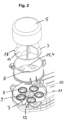
- Fig. 2 shows a perspective exploded view on the exemplary multiway-valve of Fig. 1 .
- 5 indicates the drive unit which contains here an electric motor.
- 3 refers to the rotatable hydraulic part which is a rotating plate 13 upon which a bent water guiding part 14 protrudes.
- a central opening 6 can be seen which is surrounded by peripheral openings 8 to 11.
- o-rings as sealing devices are placed around the peripheral openings 8 to 11.
- Fig. 3 shows a cut view of the exploded view of Fig. 2 on the exemplary multiway-valve of Fig. 1 .
- 5 indicates the drive unit which contains here an electric motor.
- 3 refers to the rotatable hydraulic part which is a rotating plate 13 upon which a bent water guiding part 14 protrudes.
- a central opening 6 can be seen which is surrounded by peripheral openings 8 and 10.
- o-rings as sealing devices are placed around the peripheral openings.
- Fig. 4 shows a cut view of a multiway-valve 1 which illustrates especially the rotatable hydraulic part 3 and its function.
- the rotatable hydraulic part 3 contains a bent water guiding part 14 with an inner surface 18 that has a spherical shape.
- the bent water guiding part 14 connects a central inlet 7 with a peripheral opening 8. 4 refers to a stationary bottom plate of the multiway valve, and 19 to one flat surface 19 containing the holes of the central inlet 7 and the peripheral opening 8.
- 5 indicates the drive unit which contains here an electric motor. 2 indicates the valve body.
- Fig. 5 shows the rotatable hydraulic part 3 used in an embodiment of the multiway-valve of the present invention.
- (a) is a cut side view;
- (b) is a bottom view; and
- (c) is a top view.
- the bent water guiding part with an inner surface 18 connects a central inlet 7 with a peripheral opening 8.
- 19 indicates one flat surface containing the hole 6 of the central inlet 7 and the peripheral opening 8.
- the open arrows indicate the flow direction of an aqueous liquid.
- Fig. 5 (b) the multiway-valve is seen from below through. 19 indicates one flat surface containing the hole of the central inlet and the peripheral opening. These cannot be seen here since they are covered by the opening 15 of the bent water guiding part.
- Fig. 5 (c) is a top view wherein the bent water guiding part 14 of the rotatable hydraulic part 3 can be seen.
- Fig. 6 shows perspective views of the rotatable hydraulic part 3 shown in Fig. 5.
- (a) is a view from oblique above; and
- (b) is a view from oblique below.
- 13 is a rotating plate and 14 the bent water guiding part.
- 15 refers to the opening 15 of the bent water guiding part and 19 indicates one flat surface.
- Fig. 7 shows a view from the bottom, wherein the sealing interfaces 16 around the peripheral openings 8 to 12 can be seen. 19 indicates one flat surface containing the hole of the central inlet and the peripheral openings 8 to 12.
Landscapes
- Engineering & Computer Science (AREA)
- General Engineering & Computer Science (AREA)
- Mechanical Engineering (AREA)
- Multiple-Way Valves (AREA)
- Sliding Valves (AREA)
Priority Applications (2)
| Application Number | Priority Date | Filing Date | Title |
|---|---|---|---|
| EP23171075.7A EP4459162A1 (de) | 2023-05-02 | 2023-05-02 | Mehrwegeventil, wasserführendes haushaltsgerät mit dem ventil und verfahren zum betreiben des haushaltsgeräts |
| CN202410535706.1A CN118896170A (zh) | 2023-05-02 | 2024-04-30 | 多路阀、包含阀的载水家用装置以及用于操作家用装置的方法 |
Applications Claiming Priority (1)
| Application Number | Priority Date | Filing Date | Title |
|---|---|---|---|
| EP23171075.7A EP4459162A1 (de) | 2023-05-02 | 2023-05-02 | Mehrwegeventil, wasserführendes haushaltsgerät mit dem ventil und verfahren zum betreiben des haushaltsgeräts |
Publications (1)
| Publication Number | Publication Date |
|---|---|
| EP4459162A1 true EP4459162A1 (de) | 2024-11-06 |
Family
ID=86328495
Family Applications (1)
| Application Number | Title | Priority Date | Filing Date |
|---|---|---|---|
| EP23171075.7A Pending EP4459162A1 (de) | 2023-05-02 | 2023-05-02 | Mehrwegeventil, wasserführendes haushaltsgerät mit dem ventil und verfahren zum betreiben des haushaltsgeräts |
Country Status (2)
| Country | Link |
|---|---|
| EP (1) | EP4459162A1 (de) |
| CN (1) | CN118896170A (de) |
Citations (9)
| Publication number | Priority date | Publication date | Assignee | Title |
|---|---|---|---|---|
| FR2367966A1 (fr) * | 1976-10-15 | 1978-05-12 | Liautaud Jean | Repartiteur antipolluant |
| US6098646A (en) * | 1997-02-19 | 2000-08-08 | Ecolab Inc. | Dispensing system with multi-port valve for distributing use dilution to a plurality of utilization points and position sensor for use thereon |
| CN2731204Y (zh) * | 2004-10-21 | 2005-10-05 | 姜永明 | 电动四通换向阀 |
| US8528596B2 (en) * | 2008-05-06 | 2013-09-10 | Bravilor Holding B.V. | Distributor with a rotatable U-shaped connecting channel |
| US8555679B2 (en) * | 2007-08-10 | 2013-10-15 | Bsh Bosch Und Siemens Hausgeraete Gmbh | Multiple-action addition valve for a system for metering liquid or pasty washing aids and method for operating the multiple-action addition valve |
| US20150158058A1 (en) | 2011-11-22 | 2015-06-11 | Michael Saier | Device and method for connecting in a switchable manner |
| US20180335152A1 (en) * | 2015-11-20 | 2018-11-22 | Smc Corporation | Switching valve |
| CN109210238A (zh) * | 2017-06-30 | 2019-01-15 | 杭州三花研究院有限公司 | 流量控制装置 |
| US11135594B2 (en) * | 2012-07-05 | 2021-10-05 | Meso Scale Technologies, Llc. | Assay cartridge valve system |
-
2023
- 2023-05-02 EP EP23171075.7A patent/EP4459162A1/de active Pending
-
2024
- 2024-04-30 CN CN202410535706.1A patent/CN118896170A/zh active Pending
Patent Citations (10)
| Publication number | Priority date | Publication date | Assignee | Title |
|---|---|---|---|---|
| FR2367966A1 (fr) * | 1976-10-15 | 1978-05-12 | Liautaud Jean | Repartiteur antipolluant |
| US6098646A (en) * | 1997-02-19 | 2000-08-08 | Ecolab Inc. | Dispensing system with multi-port valve for distributing use dilution to a plurality of utilization points and position sensor for use thereon |
| CN2731204Y (zh) * | 2004-10-21 | 2005-10-05 | 姜永明 | 电动四通换向阀 |
| US8555679B2 (en) * | 2007-08-10 | 2013-10-15 | Bsh Bosch Und Siemens Hausgeraete Gmbh | Multiple-action addition valve for a system for metering liquid or pasty washing aids and method for operating the multiple-action addition valve |
| US8528596B2 (en) * | 2008-05-06 | 2013-09-10 | Bravilor Holding B.V. | Distributor with a rotatable U-shaped connecting channel |
| US20150158058A1 (en) | 2011-11-22 | 2015-06-11 | Michael Saier | Device and method for connecting in a switchable manner |
| EP2783142B1 (de) | 2011-11-22 | 2018-04-25 | Saier, Beatrice | Vorrichtung zum schaltbaren verbinden |
| US11135594B2 (en) * | 2012-07-05 | 2021-10-05 | Meso Scale Technologies, Llc. | Assay cartridge valve system |
| US20180335152A1 (en) * | 2015-11-20 | 2018-11-22 | Smc Corporation | Switching valve |
| CN109210238A (zh) * | 2017-06-30 | 2019-01-15 | 杭州三花研究院有限公司 | 流量控制装置 |
Also Published As
| Publication number | Publication date |
|---|---|
| CN118896170A (zh) | 2024-11-05 |
Similar Documents
| Publication | Publication Date | Title |
|---|---|---|
| US8915257B2 (en) | Water-carrying domestic appliance having a water-distribution mechanism | |
| US8978674B2 (en) | Water-bearing domestic appliance with a water diverter | |
| US20100236588A1 (en) | Water-bearing domestic appliance with a water diverter | |
| KR940006543A (ko) | 식기세척기 | |
| EP2267345B1 (de) | Ventil mit mehreren Anschlüssen | |
| KR101506718B1 (ko) | 회전식 압력 전달 장치 | |
| US10690254B2 (en) | Two eductor / four-way selector valve assembly | |
| US20070044856A1 (en) | Diverter valve for water systems | |
| JP2014185638A (ja) | 選択可能な排出口を有するポンプ | |
| CN101617226A (zh) | 用于试样注入的转动阀 | |
| US6219860B1 (en) | Faucet assembly having overlapping spouts for releasing filtered and unfiltered water therefrom | |
| US20220288656A1 (en) | Multiport valve | |
| US6364520B1 (en) | Conduction mixers | |
| US20230059236A1 (en) | Fluid delivery system for a front-load washing appliance for delivering fluid to lifters of the drum | |
| US6991934B2 (en) | Tissue processor with integrated valve | |
| EP4226043B1 (de) | Pump- und schaltvorrichtung und flüssigkeitssortiergerät | |
| EP2708178B1 (de) | Umlenkventilvorrichtung, insbesondere für Waschmaschinen wie z. B. Geschirrspüler | |
| EP0947750A2 (de) | Drei-Wege Klappenventil | |
| EP2940357A1 (de) | Flussregelventil | |
| CN118896170A (zh) | 多路阀、包含阀的载水家用装置以及用于操作家用装置的方法 | |
| KR101919501B1 (ko) | 세탁기용 급수밸브 | |
| KR101230502B1 (ko) | 혼합밸브 | |
| CN116497569B (zh) | 一种洗涤剂切换投放装置及洗涤设备 | |
| US7836913B1 (en) | Universal cartridge for a mixer faucet | |
| GB2384287A (en) | Flow reversal valve and conduit arrangement |
Legal Events
| Date | Code | Title | Description |
|---|---|---|---|
| PUAI | Public reference made under article 153(3) epc to a published international application that has entered the european phase |
Free format text: ORIGINAL CODE: 0009012 |
|
| STAA | Information on the status of an ep patent application or granted ep patent |
Free format text: STATUS: THE APPLICATION HAS BEEN PUBLISHED |
|
| AK | Designated contracting states |
Kind code of ref document: A1 Designated state(s): AL AT BE BG CH CY CZ DE DK EE ES FI FR GB GR HR HU IE IS IT LI LT LU LV MC ME MK MT NL NO PL PT RO RS SE SI SK SM TR |
|
| STAA | Information on the status of an ep patent application or granted ep patent |
Free format text: STATUS: REQUEST FOR EXAMINATION WAS MADE |
|
| 17P | Request for examination filed |
Effective date: 20250506 |