EP4459174A1 - Taschenlampe mit funktion zur erzielung einer einschlüsselverriegelung - Google Patents
Taschenlampe mit funktion zur erzielung einer einschlüsselverriegelung Download PDFInfo
- Publication number
- EP4459174A1 EP4459174A1 EP23210705.2A EP23210705A EP4459174A1 EP 4459174 A1 EP4459174 A1 EP 4459174A1 EP 23210705 A EP23210705 A EP 23210705A EP 4459174 A1 EP4459174 A1 EP 4459174A1
- Authority
- EP
- European Patent Office
- Prior art keywords
- flashlight
- toggle
- switch
- tail
- square groove
- Prior art date
- Legal status (The legal status is an assumption and is not a legal conclusion. Google has not performed a legal analysis and makes no representation as to the accuracy of the status listed.)
- Pending
Links
Images
Classifications
-
- F—MECHANICAL ENGINEERING; LIGHTING; HEATING; WEAPONS; BLASTING
- F21—LIGHTING
- F21V—FUNCTIONAL FEATURES OR DETAILS OF LIGHTING DEVICES OR SYSTEMS THEREOF; STRUCTURAL COMBINATIONS OF LIGHTING DEVICES WITH OTHER ARTICLES, NOT OTHERWISE PROVIDED FOR
- F21V23/00—Arrangement of electric circuit elements in or on lighting devices
- F21V23/04—Arrangement of electric circuit elements in or on lighting devices the elements being switches
- F21V23/0414—Arrangement of electric circuit elements in or on lighting devices the elements being switches specially adapted to be used with portable lighting devices
- F21V23/0421—Arrangement of electric circuit elements in or on lighting devices the elements being switches specially adapted to be used with portable lighting devices the switch being part of, or disposed on the tail cap portion thereof
-
- F—MECHANICAL ENGINEERING; LIGHTING; HEATING; WEAPONS; BLASTING
- F21—LIGHTING
- F21L—LIGHTING DEVICES OR SYSTEMS THEREOF, BEING PORTABLE OR SPECIALLY ADAPTED FOR TRANSPORTATION
- F21L4/00—Electric lighting devices with self-contained electric batteries or cells
- F21L4/005—Electric lighting devices with self-contained electric batteries or cells the device being a pocket lamp
-
- F—MECHANICAL ENGINEERING; LIGHTING; HEATING; WEAPONS; BLASTING
- F21—LIGHTING
- F21V—FUNCTIONAL FEATURES OR DETAILS OF LIGHTING DEVICES OR SYSTEMS THEREOF; STRUCTURAL COMBINATIONS OF LIGHTING DEVICES WITH OTHER ARTICLES, NOT OTHERWISE PROVIDED FOR
- F21V23/00—Arrangement of electric circuit elements in or on lighting devices
- F21V23/003—Arrangement of electric circuit elements in or on lighting devices the elements being electronics drivers or controllers for operating the light source, e.g. for a LED array
-
- F—MECHANICAL ENGINEERING; LIGHTING; HEATING; WEAPONS; BLASTING
- F21—LIGHTING
- F21V—FUNCTIONAL FEATURES OR DETAILS OF LIGHTING DEVICES OR SYSTEMS THEREOF; STRUCTURAL COMBINATIONS OF LIGHTING DEVICES WITH OTHER ARTICLES, NOT OTHERWISE PROVIDED FOR
- F21V23/00—Arrangement of electric circuit elements in or on lighting devices
- F21V23/04—Arrangement of electric circuit elements in or on lighting devices the elements being switches
- F21V23/0442—Arrangement of electric circuit elements in or on lighting devices the elements being switches activated by means of a sensor, e.g. motion or photodetectors
- F21V23/0457—Arrangement of electric circuit elements in or on lighting devices the elements being switches activated by means of a sensor, e.g. motion or photodetectors the sensor sensing the operating status of the lighting device, e.g. to detect failure of a light source or to provide feedback to the device
Definitions
- the present invention belongs to the technical field of flashlights, and particularly relates to a flashlight capable of achieving one-key locking.
- flashlights are widely used in outdoor adventures or in daily life, wherein batteries are used as energy sources, and the batteries and light-emitting electric beads constitute electric circuits. When switch is turned on, the circuits are connected, and currents flow through the electric beads to enable the electric beads to emit light, thereby achieving the illumination purpose.
- Power source of the traditional flashlight is connected or disconnected by means of a tail switch or a side push switch, which has a defect that when the flashlight is placed in knapsack or trousers pocket, the switches are likely to be turned on automatically due to misoperation. After touch by mistake, waste of the power source will be caused by long-time turning-on of the flashlight, and there is no power when light source is needed in emergency, resulting in poor user experience.
- the flashlight is placed in the knapsack or the trousers pocket when being turned on, local overheating occurs easily, resulting in the fire risk.
- locking can be achieved through long-time pressing or double clicking of the switch for some flashlights later in the market, however, the operation is inconvenient, and use requirements of users cannot be met.
- the present invention aims to provide a flashlight capable of achieving one-key locking, which can achieve one-key locking, avoid power waste caused when a user touches an illumination switch by mistake, is convenient to operate, and can meet users' requirements.
- the present invention may be achieved as follows:
- the flashlight includes an illumination switch, a flashlight body and a lamp base provided at one end of the flashlight body and internally provided with a lamp bead.
- the flashlight further includes a flashlight tail connected to another end of the flashlight body away from the lamp base, a control assembly fixedly provided inside the flashlight tail and in signal connection with a lamp bead driving circuit and the illumination switch respectively, and a toggle switch slidably mounted on an outer side of the flashlight tail and provided with at least two gears in a direction parallel to an axial direction of the flashlight body, where the toggle switch is configured to toggle in a reciprocating manner between the two adjacent gears so as to transmit a locking signal or an unlocking signal to the control assembly, and when the control assembly receives the locking signal from the toggle switch, the control assembly transmits a disconnection instruction to the lamp bead driving circuit; and when the control assembly receives the unlocking signal from the toggle switch, the control assembly recognizes a switch signal of the illumination switch and transmits a connection instruction or the disconnection instruction
- the control assembly performs adjustment and outputs a corresponding instruction, thereby connecting or disconnecting the lamp bead driving circuit, and then achieving one-key locking of the illumination switch of the flashlight.
- the lamp bead cannot emit light no matter whether the user presses the illumination switch of the flashlight, thereby avoiding power waste caused when the user touches the illumination switch by mistake.
- the toggle switch located on the flashlight tail and capable of moving in the direction parallel to the axial direction of the flashlight body, when the flashlight body is held by one hand, the gears can be changed by pushing the toggle switch directly in the axial direction of the flashlight body, then one-key locking of the flashlight can be achieved.
- the operation process is relatively convenient, and the use requirements of the user can be met.
- the control assembly includes a microcontroller unit (MCU) and a Hall sensor which are fixedly provided inside the flashlight tail, the Hall sensor is electrically connected to the MCU, the MCU is in signal connection with the lamp bead driving circuit and the illumination switch respectively, the toggle switch is disposed close to the Hall sensor and is configured to change an external magnetic field of the Hall sensor so as to change a voltage signal transmitted to the MCU by the Hall sensor, and the MCU is configured to recognize the locking signal or the unlocking signal according to different voltage signals.
- MCU microcontroller unit
- Hall sensor is electrically connected to the MCU
- the MCU is in signal connection with the lamp bead driving circuit and the illumination switch respectively
- the toggle switch is disposed close to the Hall sensor and is configured to change an external magnetic field of the Hall sensor so as to change a voltage signal transmitted to the MCU by the Hall sensor
- the MCU is configured to recognize the locking signal or the unlocking signal according to different voltage signals.
- the flashlight tail is inwardly provided with a sliding groove from an outer side surface
- the toggle switch is slidably embedded in the sliding groove and is provided with the two gears
- a toggle direction of the toggle switch is parallel to the axial direction of the flashlight body
- the toggle switch can be in contact with inner walls of two sides of the sliding groove parallel to the axial direction of the flashlight body respectively, so as to achieve switching of the two gears.
- the toggle switch includes a toggle key, a magnetic block and a gear slider which are sequentially connected from outside to inside, the gear slider is slidably mounted inside the sliding groove, and an outer side wall of the toggle key is exposed out of an end port of the sliding groove.
- the sliding groove includes a first square groove and a second square groove which are sequentially connected from outside to inside and have lengthwise directions parallel to the axial direction of the flashlight body, the length of the first square groove is less than the length of the second square groove, and the width of the first square groove is less than the width of the second square groove;
- the gear slider is slidably connected inside the second square groove, outer walls of two sides of the gear slider respectively abut against inner walls of two sides of the second square groove in a widthwise direction, and outer walls of another two sides of the gear slider are configured to be in contact with inner walls of two sides of the second square groove in a lengthwise direction respectively so as to achieve change of the magnetic field of the Hall sensor; and the outer side wall of the toggle key is exposed out of the first square groove.
- the middle of the gear slider is provided with an opening on the side close to the toggle key for accommodating the magnetic block, and the toggle key is snap-fitted with the gear slider and blocks the opening so as to fix the magnetic block.
- two ends of the gear slider are symmetrically provided with two snap-fitting grooves, and the side of the toggle key close to the gear slider is provided with two protrusions fitted with the snap-fitting grooves.
- the side of the toggle key away from the gear slider is provided with anti-slip stripes.
- the flashlight tail is set as a cylindrical body and is fixedly mounted at the end of the flashlight body away from the lamp base.
- the illumination switch is set as a push switch, and the push switch is mounted on the side of the flashlight tail away from the flashlight body.
- the present invention has the beneficial effects as follows: By pushing the toggle switch provided on the flashlight tail, switching of the different gears is achieved and a corresponding signal is transmitted to the control assembly, and after receiving the corresponding signal, the control assembly performs adjustment and outputs a corresponding instruction, thereby connecting or disconnecting the lamp bead driving circuit, and then achieving one-key locking of the illumination switch of the flashlight. After locking, the lamp bead cannot emit light no matter whether the user presses the illumination switch of the flashlight, thereby avoiding power waste caused when the user touches the illumination switch by mistake.
- the toggle switch located on the flashlight tail and capable of moving in the direction parallel to the axial direction of the flashlight body, when the flashlight body is held by one hand, the gears can be changed by pushing the toggle switch directly in the axial direction of the flashlight body, then one-key locking of the flashlight can be achieved.
- the operation process is relatively convenient, and the use requirements of the user can be met.
- first and second are only for the purpose of describing, and cannot be understood as indicating or implying the relative importance or implicitly indicating the number of technical features indicated. Thus, the features defined as “first” and “second” may explicitly or implicitly include one or more such features. In the descriptions of the embodiments of the present application, unless otherwise specified, "a plurality of' means two or more.
- orientation terms “upper”, “lower”, “left”, “right” and the like are defined relative to the schematic placement orientations of components in the drawings, and it should be understood that these orientation terms are relative concepts used for relative descriptions and clarifications and can be changed correspondingly according to the change of the placement orientations of the components in the drawings.
- connection should be understood in a broad sense, for example, the “connection” can be fixed connection, or detachable connection, or integral connection; and it can be direct connection or indirect connection by means of an intermediate medium.
- the term "including”, “comprising” or any other variation thereof is intended to cover the non-exclusive inclusion, such that a process, method, object or device including a series of elements includes not only those elements, but also other elements that are not explicitly listed, or also include inherent elements of the process, method, object or device.
- an element defined by the statement "including a/an" does not exclude the existence of other identical elements in the process, method, object or device including the element.
- the wording "exemplary” or “for example” are used to indicate an example, an illustration, or an explanation. In the embodiments of the present application, any embodiment or design scheme described as “exemplary” or “for example” should not be explained as more preferred or advantageous than other embodiments or design schemes.
- the wording "exemplary” or “for example” is used to present a relevant concept in a specific manner.
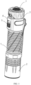
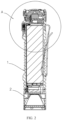
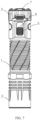
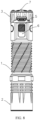
- the flashlight includes an illumination switch 7, a flashlight body 1 and a lamp base 2 provided at one end of the flashlight body 1 and internally provided with a lamp bead.
- the flashlight further includes a flashlight tail 3 connected to another end of the flashlight body 1 away from the lamp base 2, a control assembly fixedly provided inside the flashlight tail 3 and in signal connection with a lamp bead driving circuit and the illumination switch 7 respectively, and a toggle switch 5 slidably mounted on an outer side of the flashlight tail 3 and provided with at least two gears in a direction parallel to an axial direction of the flashlight body 1, where the toggle switch 5 is configured to toggle in a reciprocating manner between the two adjacent gears so as to transmit a locking signal or an unlocking signal to the control assembly, and when the control assembly receives the locking signal from the toggle switch 5, the control assembly transmits a disconnection instruction to the lamp bead driving circuit; and when the control assembly receives the unlocking signal from the toggle switch 5, the control assembly recognizes a switch signal of the illumination switch 7 and transmits a connection instruction or the disconnection instruction to the lamp bead driving circuit according to a recognition result.
- the lamp bead cannot emit light no matter whether a user presses the illumination switch 7 of the flashlight, thereby avoiding power waste caused when the user touches the illumination switch 7 by mistake; in addition, by means of the toggle switch 5 located on the flashlight tail 3 and capable of moving in the direction parallel to the axial direction of the flashlight body 1, when the flashlight body 1 is held by one hand, the gears can be changed by pushing the toggle switch 5 directly in the axial direction of the flashlight body 1, then one-key locking of the flashlight can be achieved, the operation process is relatively convenient, and use requirements of the user can be met.
- FIGS. 7 and 8 which correspond to structure diagrams of the flashlight in an unlocked state and in a locked state in sequence, when the lamp bead driving circuit is locked, the illumination switch 7 of the flashlight is also disabled, thereby achieving one-key locking of the flashlight.
- the gears of the toggle switch 5 can be set as required, thereby achieving the states of the lamp bead driving circuit in correspondence to the different gears, for example, in addition to connecting and disconnecting the lamp bead driving circuit, the different gears can also correspond to different brightness or colors of the lamp bead, and thus the number of the gears of the toggle switch 5 is not specified restrictively.
- the control assembly includes an MCU and a Hall sensor 4 which are fixedly provided inside the flashlight tail 3.
- the Hall sensor 4 is electrically connected to the MCU, the MCU is in signal connection with the lamp bead driving circuit and the illumination switch 7 respectively, the toggle switch 5 is disposed close to the Hall sensor 4 and is configured to change an external magnetic field of the Hall sensor so as to change a voltage signal transmitted to the MCU by the Hall sensor 4, and the MCU is configured to recognize the locking signal or the unlocking signal according to different voltage signals.
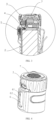
- the flashlight tail 3 is inwardly provided with a sliding groove 6 from an outer side surface
- the toggle switch 5 is slidably embedded in the sliding groove 6 and is provided with the two gears
- a toggle direction of the toggle switch 5 is parallel to the axial direction of the flashlight body 1
- the toggle switch can be in contact with inner walls of two sides of the sliding groove 6 parallel to the axial direction of the flashlight body 1 respectively, so as to achieve switching of the two gears.
- the toggle switch 5 can be mounted conveniently, and the toggle direction thereof can be limited, thereby ensuring that the actual toggle direction is parallel to the axial direction of the flashlight body 1; and the toggle switch 5 is in contact with the inner walls of the two sides of the sliding groove 6 respectively, thereby achieving switching of the two gears, which correspond to unlocking and locking of the flashlight.
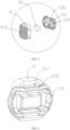
- the toggle switch 5 includes a toggle key 51, a magnetic block 52 and a gear slider 53 which are sequentially connected from outside to inside, the gear slider 53 is slidably mounted inside the sliding groove 6, and an outer side wall of the toggle key 51 is exposed out of an end port of the sliding groove 6.
- the sliding groove 6 includes a first square groove 61 and a second square groove 62 which are sequentially connected from outside to inside and have lengthwise directions parallel to the axial direction of the flashlight body 1.
- the length of the first square groove 61 is less than the length of the second square groove 62
- the width of the first square groove 61 is less than the width of the second square groove 62.
- the gear slider 53 is slidably connected inside the second square groove 62, outer walls of two sides of the gear slider respectively abut against inner walls of two sides of the second square groove 62 in a widthwise direction, and outer walls of another two sides of the gear slider are configured to be in contact with inner walls of two sides of the second square groove 62 in a lengthwise direction respectively so as to achieve change of the magnetic field of the Hall sensor 4; and the outer side wall of the toggle key 51 is exposed out of the first square groove 61.
- the toggle switch 5 is configured to include the toggle key 51, the magnetic block 52 and the gear slider 53 which are assembled sequentially, and the gear slider 53 slidably abuts against the inner walls of the two sides of the second square groove 62 in the widthwise direction, such that the entire toggle switch 5 reciprocates in the direction parallel to the axial direction of the flashlight body 1, and there is a certain pre-tightening force with the inner walls of the two sides, which prevents the gear slider 53 from moving freely in an unrestrained manner inside the second square groove 62; and the inner walls of the two sides of the second square groove 62 in the lengthwise direction can sequentially correspond to the two gears of the toggle switch 5, thereby achieving switching of the two states.
- the Hall sensor 4 can be subjected to magnetic induction with the magnetic block 52 of the toggle switch 5.
- the toggle switch 5 drives the magnetic block 52 to move in the toggle process
- the Hall sensor 4 detects the change of the magnetic field so as to convert a changed magnetic field signal into the voltage signal and output the same to the MCU
- the MCU can detect the position of the toggle switch 5 after processing the voltage signal and can receive the locking signal or the unlocking signal of the toggle switch, in combination with a digital signal of the illumination switch 7, after program logic operation
- the MCU can obtain an instruction for controlling connection and disconnection of the lamp bead driving circuit and transmit the instruction to the lamp bead driving circuit, thereby adjusting the working state thereof, and achieving connection and disconnection of the lamp bead driving circuit.
- signal transmission can be performed on the MCU by means of a toggle stop block and an optical sensor, thereby transmitting the locking signal or the unlocking signal.
- An external signal transmission element can also be used to transmit the locking signal or the unlocking signal to the MCU, and then the MCU further recognizes and judges the digital signal of the illumination switch 7 so as to determine transmission of the connection instruction or the disconnection instruction to the lamp bead driving circuit. Therefore, the transmission manner for the locking signal and the unlocking signal is not specified restrictively in this embodiment.
- the middle of the gear slider 53 is provided with an opening 531 on the side close to the toggle key 51 for accommodating the magnetic block 52, and the toggle key 51 is snap-fitted with the gear slider 53 and blocks the opening 531 so as to fix the magnetic block 52.
- the opening 531 formed on the side of the gear slider 53 close to the toggle key 51 can accommodate the toggle key 51, and the toggle switch 5 snap-fitted with the gear slider 53 is configured to block the opening 531 so as to mount and fix the magnetic block 52.
- two ends of the gear slider 53 are symmetrically provided with two snap-fitting grooves 532, and the side of the toggle key 51 close to the gear slider 53 is provided with two protrusions 511 fitted with the snap-fitting grooves 532.
- the two snap-fitting grooves 532 symmetrically formed at the two ends of the gear slider 53 can be fitted with the two protrusions 511 at two ends of the toggle key 51 to achieve snap-fitting and fixing of the toggle key 51 and the gear slider 53.
- the side of the toggle key 51 away from the gear slider 53 is provided with anti-slip stripes 512.
- the flashlight tail 3 is set as a cylindrical body and is fixedly mounted at the end of the flashlight body 1 away from the lamp base 2.
- the flashlight tail 3 is set as the cylindrical body to facilitate holding by hand, and the flashlight tail 3 is fixedly mounted at the tail end of the flashlight body 1 such that part of a battery connection device and other control devices can be accommodated inside the flashlight tail.
- the illumination switch 7 is set as a push switch, and the push switch is mounted on the side of the flashlight tail 3 away from the flashlight body 1.
- on/off signals of the lamp bead of the flashlight can be transmitted conveniently by means of the illumination switch 7, the illumination switch 7 can be pressed to transmit digital signals for turning on and turning off the lamp bead to the MCU, and thus the MCU can recognize and judge the signals conveniently; and the illumination switch is provided on the side of the flashlight tail 3 away from the flashlight body 1, such that when the flashlight is held by one hand, the flashlight can be turned on and turned off quickly and more conveniently.
- the flashlight tail in addition to directly fixing the flashlight tail 3 to the tail end of the flashlight body 1 in this embodiment, the flashlight tail can also be mounted at the tail end of the flashlight body 1 in a threaded manner, thereby achieving split production of the flashlight body 1 and the flashlight tail 3. Therefore, the mounting manner for the flashlight tail 3 is not specified restrictively.
- the flashlight capable of achieving one-key locking is provided in the above embodiments of the present invention, by pushing the toggle switch 5 provided on the flashlight tail 3, switching of the different gears is achieved and a corresponding signal is transmitted to the control assembly, and after receiving the corresponding signal, the control assembly performs adjustment and outputs a corresponding instruction, thereby connecting or disconnecting the lamp bead driving circuit, and then achieving one-key locking of the illumination switch 7 of the flashlight.
- the lamp bead cannot emit light no matter whether the user presses the illumination switch 7 of the flashlight, thereby avoiding power waste caused when the user touches the illumination switch 7 by mistake; in addition, by means of the toggle switch 5 located on the flashlight tail 3 and capable of moving in the direction parallel to the axial direction of the flashlight body 1, when the flashlight body 1 is held by one hand, the gears can be changed by pushing the toggle switch 5 directly in the axial direction of the flashlight body 1, then one-key locking of the flashlight can be achieved, the operation process is relatively convenient, and the use requirements of the user can be met.
Landscapes
- Engineering & Computer Science (AREA)
- General Engineering & Computer Science (AREA)
- Microelectronics & Electronic Packaging (AREA)
- Arrangement Of Elements, Cooling, Sealing, Or The Like Of Lighting Devices (AREA)
Applications Claiming Priority (1)
| Application Number | Priority Date | Filing Date | Title |
|---|---|---|---|
| CN202322748377.2U CN221035642U (zh) | 2023-10-12 | 2023-10-12 | 一种一键锁定的手电筒 |
Publications (1)
| Publication Number | Publication Date |
|---|---|
| EP4459174A1 true EP4459174A1 (de) | 2024-11-06 |
Family
ID=88839486
Family Applications (1)
| Application Number | Title | Priority Date | Filing Date |
|---|---|---|---|
| EP23210705.2A Pending EP4459174A1 (de) | 2023-10-12 | 2023-11-17 | Taschenlampe mit funktion zur erzielung einer einschlüsselverriegelung |
Country Status (3)
| Country | Link |
|---|---|
| US (1) | US12203638B1 (de) |
| EP (1) | EP4459174A1 (de) |
| CN (1) | CN221035642U (de) |
Cited By (1)
| Publication number | Priority date | Publication date | Assignee | Title |
|---|---|---|---|---|
| CN120312995A (zh) * | 2025-05-07 | 2025-07-15 | 广东皓昇光电科技有限公司 | 一种可调节照明方向的手电筒 |
Citations (6)
| Publication number | Priority date | Publication date | Assignee | Title |
|---|---|---|---|---|
| US20070258236A1 (en) * | 2006-05-03 | 2007-11-08 | Quantum Leap Research Inc. | Hand-held lighting device with waterproof lock-out tail cap |
| US20100046211A1 (en) * | 2008-08-20 | 2010-02-25 | Eveready Battery Company, Inc. | Lighting Device Configured to Operate with Different Batteries |
| US7802898B1 (en) * | 2004-10-19 | 2010-09-28 | Blackhawk Industries Product Group Unlimited Llc | Lightning device |
| US20130265749A1 (en) * | 2012-01-24 | 2013-10-10 | Tactical Impulse Llc | Modular flashlight system |
| US10344959B2 (en) * | 2017-11-20 | 2019-07-09 | Streamlight, Inc. | Portable and/or mountable light |
| CN213018998U (zh) * | 2020-07-23 | 2021-04-20 | 深圳市傲雷电商科技股份有限公司 | 一种磁感应控制的led手电筒 |
Family Cites Families (14)
| Publication number | Priority date | Publication date | Assignee | Title |
|---|---|---|---|---|
| US8096674B2 (en) * | 2003-12-09 | 2012-01-17 | Surefire, Llc | Lighting device with selectable output level switching |
| US7186002B2 (en) * | 2003-12-09 | 2007-03-06 | Surefire Llc | Flashlight with selectable output level switching |
| US7220016B2 (en) * | 2003-12-09 | 2007-05-22 | Surefire, Llc | Flashlight with selectable output level switching |
| US7293893B2 (en) * | 2003-12-09 | 2007-11-13 | Surefire Llc | Flashlight with adjustable color selector switch |
| US7527388B2 (en) * | 2003-12-09 | 2009-05-05 | Surefire Llc | Flashlight with detented rotary control |
| US7344270B2 (en) * | 2003-12-09 | 2008-03-18 | Surefire, Llc | Flashlight with incrementing brightness selector switch |
| GB0520975D0 (en) * | 2005-10-14 | 2005-11-23 | Noble Barry A | Programmable lighting device |
| US7441920B2 (en) * | 2006-07-13 | 2008-10-28 | Pelican Products, Inc. | Multi-switch flashlight |
| US7922350B1 (en) * | 2007-05-08 | 2011-04-12 | L-3 Insight Technology Incorporated | Tactical illuminator |
| US8529086B2 (en) * | 2010-02-23 | 2013-09-10 | Black Diamond Equipment Ltd. | Systems and methods for locking a portable illumination system |
| US20120002691A1 (en) * | 2010-06-30 | 2012-01-05 | Tao xiao wei | System and method for providing a safety mechanism for a laser-emitting device |
| US9188292B2 (en) * | 2010-11-17 | 2015-11-17 | Light & Motion Industries | Diver's underwater light for selecting between two types of light |
| EP3187770A1 (de) * | 2016-01-04 | 2017-07-05 | Zedel S.A. | Tragbare lampe mit verbessertem verriegelungsmechanismus |
| US11421833B2 (en) * | 2020-01-20 | 2022-08-23 | Streamlight, Inc. | Multifunction portable light and actuator |
-
2023
- 2023-10-12 CN CN202322748377.2U patent/CN221035642U/zh active Active
- 2023-11-17 EP EP23210705.2A patent/EP4459174A1/de active Pending
- 2023-11-17 US US18/512,416 patent/US12203638B1/en active Active
Patent Citations (6)
| Publication number | Priority date | Publication date | Assignee | Title |
|---|---|---|---|---|
| US7802898B1 (en) * | 2004-10-19 | 2010-09-28 | Blackhawk Industries Product Group Unlimited Llc | Lightning device |
| US20070258236A1 (en) * | 2006-05-03 | 2007-11-08 | Quantum Leap Research Inc. | Hand-held lighting device with waterproof lock-out tail cap |
| US20100046211A1 (en) * | 2008-08-20 | 2010-02-25 | Eveready Battery Company, Inc. | Lighting Device Configured to Operate with Different Batteries |
| US20130265749A1 (en) * | 2012-01-24 | 2013-10-10 | Tactical Impulse Llc | Modular flashlight system |
| US10344959B2 (en) * | 2017-11-20 | 2019-07-09 | Streamlight, Inc. | Portable and/or mountable light |
| CN213018998U (zh) * | 2020-07-23 | 2021-04-20 | 深圳市傲雷电商科技股份有限公司 | 一种磁感应控制的led手电筒 |
Cited By (1)
| Publication number | Priority date | Publication date | Assignee | Title |
|---|---|---|---|---|
| CN120312995A (zh) * | 2025-05-07 | 2025-07-15 | 广东皓昇光电科技有限公司 | 一种可调节照明方向的手电筒 |
Also Published As
| Publication number | Publication date |
|---|---|
| US12203638B1 (en) | 2025-01-21 |
| CN221035642U (zh) | 2024-05-28 |
Similar Documents
| Publication | Publication Date | Title |
|---|---|---|
| EP4459174A1 (de) | Taschenlampe mit funktion zur erzielung einer einschlüsselverriegelung | |
| US20110133696A1 (en) | Accessory and charging system for a rechargeable hand-held electrical device | |
| CN107332090A (zh) | 转接器、光源装置和照明设备 | |
| AU2016281399B2 (en) | Lighting module tightening device for lamp | |
| US7188966B1 (en) | Hand tool with illuminator | |
| CN210405742U (zh) | 一种应用电子技术的无线照明遥控器 | |
| CN218845817U (zh) | 一种led小夜灯 | |
| GB2415494A (en) | Emergency lamp | |
| CN219756284U (zh) | 一种外置雷达感应器的led灯 | |
| WO2013015506A1 (ko) | 휴대기능을 가지는 조명등 | |
| CN210113027U (zh) | 一种油田井下作业用维修工具 | |
| CN112833341A (zh) | 一种多途径供电的工具灯 | |
| JP4826534B2 (ja) | 配線システム | |
| CN205488849U (zh) | 一种带有开关的新型节能插头 | |
| CN216849682U (zh) | 一种充电式电动工具开关 | |
| CN216291525U (zh) | 一种基于无线有线技术的共生混合型照明控制开关 | |
| CN220083014U (zh) | 支持热插拔感应开关的led灯具 | |
| CN214315226U (zh) | 一种触摸按钮开关 | |
| JP2003141914A (ja) | 多機能照明具 | |
| CN218064796U (zh) | 机械复位式手电筒 | |
| CN115574659B (zh) | 一种尾部开关结构及其枪灯 | |
| CN107477535B (zh) | 转接器、光源装置和照明设备 | |
| CN218384872U (zh) | 一种电路用开关 | |
| CN220474513U (zh) | 迷你型按钮信号开关 | |
| CN211780947U (zh) | 一种拆装方便的led驱动电源 |
Legal Events
| Date | Code | Title | Description |
|---|---|---|---|
| PUAI | Public reference made under article 153(3) epc to a published international application that has entered the european phase |
Free format text: ORIGINAL CODE: 0009012 |
|
| STAA | Information on the status of an ep patent application or granted ep patent |
Free format text: STATUS: REQUEST FOR EXAMINATION WAS MADE |
|
| 17P | Request for examination filed |
Effective date: 20240326 |
|
| AK | Designated contracting states |
Kind code of ref document: A1 Designated state(s): AL AT BE BG CH CY CZ DE DK EE ES FI FR GB GR HR HU IE IS IT LI LT LU LV MC ME MK MT NL NO PL PT RO RS SE SI SK SM TR |
|
| GRAP | Despatch of communication of intention to grant a patent |
Free format text: ORIGINAL CODE: EPIDOSNIGR1 |
|
| STAA | Information on the status of an ep patent application or granted ep patent |
Free format text: STATUS: GRANT OF PATENT IS INTENDED |