EP4459178A2 - Lampe avec plaque de support - Google Patents
Lampe avec plaque de support Download PDFInfo
- Publication number
- EP4459178A2 EP4459178A2 EP24167318.5A EP24167318A EP4459178A2 EP 4459178 A2 EP4459178 A2 EP 4459178A2 EP 24167318 A EP24167318 A EP 24167318A EP 4459178 A2 EP4459178 A2 EP 4459178A2
- Authority
- EP
- European Patent Office
- Prior art keywords
- fastening
- lamp
- section
- support plate
- elongated
- Prior art date
- Legal status (The legal status is an assumption and is not a legal conclusion. Google has not performed a legal analysis and makes no representation as to the accuracy of the status listed.)
- Granted
Links
Images











Classifications
-
- F—MECHANICAL ENGINEERING; LIGHTING; HEATING; WEAPONS; BLASTING
- F21—LIGHTING
- F21V—FUNCTIONAL FEATURES OR DETAILS OF LIGHTING DEVICES OR SYSTEMS THEREOF; STRUCTURAL COMBINATIONS OF LIGHTING DEVICES WITH OTHER ARTICLES, NOT OTHERWISE PROVIDED FOR
- F21V23/00—Arrangement of electric circuit elements in or on lighting devices
- F21V23/06—Arrangement of electric circuit elements in or on lighting devices the elements being coupling devices, e.g. connectors
-
- F—MECHANICAL ENGINEERING; LIGHTING; HEATING; WEAPONS; BLASTING
- F21—LIGHTING
- F21S—NON-PORTABLE LIGHTING DEVICES; SYSTEMS THEREOF; VEHICLE LIGHTING DEVICES SPECIALLY ADAPTED FOR VEHICLE EXTERIORS
- F21S4/00—Lighting devices or systems using a string or strip of light sources
- F21S4/20—Lighting devices or systems using a string or strip of light sources with light sources held by or within elongate supports
- F21S4/28—Lighting devices or systems using a string or strip of light sources with light sources held by or within elongate supports rigid, e.g. LED bars
-
- F—MECHANICAL ENGINEERING; LIGHTING; HEATING; WEAPONS; BLASTING
- F21—LIGHTING
- F21V—FUNCTIONAL FEATURES OR DETAILS OF LIGHTING DEVICES OR SYSTEMS THEREOF; STRUCTURAL COMBINATIONS OF LIGHTING DEVICES WITH OTHER ARTICLES, NOT OTHERWISE PROVIDED FOR
- F21V15/00—Protecting lighting devices from damage
- F21V15/01—Housings, e.g. material or assembling of housing parts
- F21V15/013—Housings, e.g. material or assembling of housing parts the housing being an extrusion
-
- F—MECHANICAL ENGINEERING; LIGHTING; HEATING; WEAPONS; BLASTING
- F21—LIGHTING
- F21V—FUNCTIONAL FEATURES OR DETAILS OF LIGHTING DEVICES OR SYSTEMS THEREOF; STRUCTURAL COMBINATIONS OF LIGHTING DEVICES WITH OTHER ARTICLES, NOT OTHERWISE PROVIDED FOR
- F21V19/00—Fastening of light sources or lamp holders
- F21V19/001—Fastening of light sources or lamp holders the light sources being semiconductors devices, e.g. LEDs
- F21V19/003—Fastening of light source holders, e.g. of circuit boards or substrates holding light sources
- F21V19/0045—Fastening of light source holders, e.g. of circuit boards or substrates holding light sources by tongue and groove connections, e.g. dovetail interlocking means fixed by sliding
-
- F—MECHANICAL ENGINEERING; LIGHTING; HEATING; WEAPONS; BLASTING
- F21—LIGHTING
- F21V—FUNCTIONAL FEATURES OR DETAILS OF LIGHTING DEVICES OR SYSTEMS THEREOF; STRUCTURAL COMBINATIONS OF LIGHTING DEVICES WITH OTHER ARTICLES, NOT OTHERWISE PROVIDED FOR
- F21V21/00—Supporting, suspending, or attaching arrangements for lighting devices; Hand grips
- F21V21/02—Wall, ceiling, or floor bases; Fixing pendants or arms to the bases
- F21V21/025—Elongated bases having a U-shaped cross section
-
- F—MECHANICAL ENGINEERING; LIGHTING; HEATING; WEAPONS; BLASTING
- F21—LIGHTING
- F21Y—INDEXING SCHEME ASSOCIATED WITH SUBCLASSES F21K, F21L, F21S and F21V, RELATING TO THE FORM OR THE KIND OF THE LIGHT SOURCES OR OF THE COLOUR OF THE LIGHT EMITTED
- F21Y2103/00—Elongate light sources, e.g. fluorescent tubes
- F21Y2103/10—Elongate light sources, e.g. fluorescent tubes comprising a linear array of point-like light-generating elements
-
- F—MECHANICAL ENGINEERING; LIGHTING; HEATING; WEAPONS; BLASTING
- F21—LIGHTING
- F21Y—INDEXING SCHEME ASSOCIATED WITH SUBCLASSES F21K, F21L, F21S and F21V, RELATING TO THE FORM OR THE KIND OF THE LIGHT SOURCES OR OF THE COLOUR OF THE LIGHT EMITTED
- F21Y2115/00—Light-generating elements of semiconductor light sources
- F21Y2115/10—Light-emitting diodes [LED]
Definitions
- the present invention relates to an elongated luminaire with a support plate for fastening current-carrying luminaire components, such as connection terminals, as well as a luminaire system equipped with this luminaire with a luminaire support rail that accommodates the luminaire.
- the present invention also relates to a retaining spring for fastening the luminaire in the luminaire support rail.
- Elongated lights of the type mentioned at the beginning are generally known. These can be, for example, so-called light bars, which are used in elongated light support rail systems. Such lights usually have an elongated light carrier in which an elongated light source, such as an LED module, is accommodated to emit light. Optical elements such as lenses can be arranged in the light path of the light emitted by the light source in order to adjust the light emission characteristics as required. To accommodate it in the light carrier, the light source can be inserted lengthways into the light carrier. In this case, the light source must then be secured against unwanted slipping out. Additional fastening means such as screws are usually used for this purpose.
- optical element can, for example, be guided through the light source and fastened in the light carrier in order to fix the light source in the desired position. It is also conceivable to provide separate fastening structures such as locking pins or locking springs.
- the optical element can also be inserted into the light carrier in a similar way. The optical element can then be provided with additional locking structures, such as locking hooks, which can snap into corresponding locking structures on the side of the light carrier. The optical element can also be fixed in place using the additional fastening means described above, similar to the light source.
- Such luminaires can have separate elements as a protective barrier against electric shock, which, for example, act as a cover to block corresponding access options (e.g. openings) in the luminaire carrier. These access options are used for assembly or maintenance, for example, but should be blocked when the luminaire is in operation.
- access options e.g. openings
- corresponding luminaires usually have fastening or locking elements which are attached to the luminaire carrier in order to lock it into the elongated luminaire support rail to form a luminaire system.
- the present invention relates to an elongated lamp which extends along a longitudinal axis.
- the lamp has a lamp carrier with a rear side and a front side.
- the lamp carrier extends longitudinally with respect to the longitudinal axis between two axially opposite end faces.
- the lamp also has an elongated lamp for emitting light at least over the front side of the lamp carrier.
- the lamp also has a support plate for fastening current-carrying lamp components.
- the lamp carrier has a holding section on its front side for supportingly receiving the lamp.
- the lamp carrier also has an open insertion area of the holding section on at least one of the end faces, via which the lamp can be slidably inserted into the holding section in an insertion direction oriented parallel to the longitudinal axis in order to be received therein in a form-fitting manner perpendicular to the longitudinal axis.
- the support plate has a fastening section with which the support plate can be fastened or fastened to the rear side of the lamp carrier.
- the support plate has a blocking section which is formed in one piece with the fastening section and which, when the support plate is fastened to the rear side of the lamp carrier above the fastening section, extends at least partially in front of the insertion region in such a way as to secure the light source received in the holding section against sliding out of the holding section via the insertion region against the insertion direction.
- the support plate serves to attach current-carrying lamp components, which can therefore preferably be provided together, which in turn facilitates the assembly of these components and their positioning.
- current-carrying luminaire components are understood to mean in particular those luminaire components which are themselves intended to conduct and possibly also use electrical current (e.g. connection terminals or operating devices) or which are intended to accommodate corresponding current-carrying elements or devices (e.g. strain relief for the passage and fixing of electrical conductors/cables).
- the support plate serves to secure the position of an inserted lamp, so that complex fastening structures and fastening elements as well as corresponding fastening steps are not necessary.
- its functional sections - namely the fastening section and the blocking section - are positioned accordingly, so that several functions can be fulfilled or provided simultaneously with just this one fastening step.
- the support plate can also serve as contact protection for the lamp because its blocking section is designed to at least partially cover the inserted lamp on the side.
- the fastening section which can be designed if necessary in such a way that it can cover corresponding access areas, for example to protect against electric shock.
- the blocking section can extend in front of the entire insertion area when the support plate is attached to the rear of the lamp carrier via the fastening section. This means that the lamp can be effectively secured against slipping out of the holding section, while at the same time providing effective protection against contact.
- the support plate can preferably be detachably connected to the lamp body, preferably by means of a screw or a screw connection. In this way, the support plate can be easily installed. The support plate can also be easily removed or replaced if necessary - for example in the event of maintenance.
- the support plate is preferably made in one piece as a stamped and bent part from a sheet metal material. This means that the support plate can be manufactured in a simple, effective and cost-effective manner.
- the support plate itself or in the longitudinal section preferably has an L-shape.
- the support plate therefore has a particularly simple but functionally highly effective shape.
- the support plate can thus be manufactured easily and inexpensively, while the corresponding functional areas - namely the fastening section and the blocking section - can be easily provided.
- the blocking section and the fastening section preferably extend away from each other at an angle to each other and particularly preferably enclose a right angle ⁇ .
- the two functional sections mentioned can be easily provided oriented to each other as required. If they enclose a right angle, this preferably results in the L-shape described above.
- the blocking section preferably extends from a front edge, preferably a narrow side, of the fastening section.
- the support plate can thus be provided in a simple manner and as compactly as possible. If the blocking section is also provided on the narrow side of the fastening section, the fastening section can consequently be provided along the lamp support and can thus be provided over a large area despite the compact design of the lamp.
- the blocking section and/or the fastening section preferably each extend in one plane.
- the two sections can therefore be designed like plates, for example. This results in a simple structure of the carrier with an overall compact but effectively functional design.
- the blocking section preferably extends from the fastening section to the front of the lamp support when the support plate is fastened to the rear of the lamp support above the fastening section.
- the lamp can preferably also have an elongated optical element for influencing the light emitted by the lamp.
- the optical element can, for example, have lenses and/or diffusers or form these.
- the lamp carrier is then further designed such that the optical element can be inserted into the holding section in a sliding manner along the insertion area in the insertion direction, in order to be held therein in a form-fitting manner perpendicular to the longitudinal axis and then preferably in a light path of the light emitted by the lamp.
- both the lamp and the optical element can be held in the same way in the lamp carrier. This simple holding enables simple and preferably automated production or assembly.
- the blocking section can preferably also be designed in such a way that, when the support plate is fastened to the rear of the lamp carrier via the fastening section, it extends at least partially in front of the insertion area in order to also secure the optical element held in the holding section against sliding out of the holding section via the insertion area against the insertion direction.
- the support plate can be used not only to secure the light source, but also to secure the optical element. This means that the functionality of the support plate can be further increased.
- the structure of the lamp as a whole can be simplified and its manufacture and assembly can be further simplified.
- the holding section preferably has a support section which supports the received illuminant on both sides of the longitudinal axis.
- the holding section can preferably have a further support section which supports the accommodated optical element on both sides of the longitudinal axis. This means that an optionally provided optical element can also be supported simply and effectively in the same way as the light source.
- the further support section can preferably be arranged offset towards the front with respect to the support section, so that when the light source and the optical element are provided, they can be placed in a defined and functionally coordinated arrangement. This simplifies assembly and reduces the risk of incorrect installation.
- the holding section or, if present, its support section or sections can preferably have U-shaped rail sections that are open towards each other on both sides of the longitudinal axis for receiving the light source or the optical element. This makes it possible to provide a simple structure for safely and effectively receiving the corresponding components.
- the rail sections can preferably each extend parallel to the longitudinal axis; this is particularly preferred between the two end faces. This enables the corresponding components to be held effectively and securely via the rail sections. Alternatively or additionally, it is also conceivable for the rail sections to each have rail sections distributed along the longitudinal axis. This enables the corresponding components to be stored effectively in the holding section in a way that protects the material.
- the blocking section can have a projection section at an end distal to the fastening section, which extends in front of a part of the insertion area when the support plate is fastened to the rear of the light carrier via the fastening section. This means that desired areas of the insertion area can be covered in a defined manner even when the support plate is manufactured in a way that protects the material.
- the projection sections preferably extend at least partially in front of the further support section and/or in front of the rail sections or into the rail sections. This means that the projection sections can be provided in a targeted and effective manner.
- the elongated light source can preferably have at least one LED module.
- LED modules are particularly characterized by high efficiency and durability as well as a compact design.
- the LED module preferably has an elongated circuit board and at least one LED arranged thereon. If the LED module has several LEDs, these are preferably arranged in one or more rows on the circuit board, preferably extending parallel to the longitudinal axis. Preferably, two parallel longitudinal edges of the circuit board can serve for supporting accommodation in the holding section. The light source can thus be accommodated effectively in the light carrier in a simple and compact manner.
- the support plate and preferably at least its fastening section can preferably have fastening structures for fastening current-carrying lighting components. These make it easier to provide corresponding components on the support plate.
- the fastening structures can have through-openings and/or recesses in the support plate, which are particularly preferably formed in the support plate by means of separation processes.
- simple and easy-to-provide fastening structures can be provided directly during the manufacture of the support plate (for example in a common punching and bending process).
- through-openings can preferably also be used as an orientation aid for the correct positioning of the support plate on the light carrier. For example, an operator can see an assembly marking provided behind it on the light carrier through the through-openings and thus ensure that the support plate is in the correct position.
- the luminaire can also have current-carrying luminaire components which can be or are directly fastened to the support plate and preferably its fastening section.
- the current-carrying luminaire components can preferably be or be fastened detachably to the support plate.
- the fastening structures described above can particularly preferably be used to fasten the current-carrying luminaire components to the support plate.
- the current-carrying luminaire components can then preferably have locking structures corresponding to the fastening structures or other structures or elements for fastening (preferably positive and/or non-positive).
- the luminaire can thus be equipped with corresponding components in any manner. Since these are advantageously combined on the support plate, handling these components while maintaining their relative positioning and orientation to one another is particularly easy. A luminaire equipped with them can therefore also be easily manufactured, preferably in an automated manufacturing or assembly process.
- the current-carrying lighting components can be, for example, a connection terminal and/or a strain relief for securing a cable and/or a status LED and the like.
- a corresponding status LED can, for example, have a fastening structure (as an element that preferably corresponds to the fastening structures), such as a retaining hook or a retaining wire, which is then fastened accordingly in the support plate. This can then, for example, be hooked into the fastening structures accordingly in order to hold the status LED securely in a defined position - for example facing the front. The functionality of the support plate can thus be increased even further.
- the present invention further relates to a lighting system (also referred to as a "lighting support rail system" in the context of the present invention), which, in addition to the previously described light according to the invention, also has an elongated light support rail for receiving the light. The light is then preferably received in the light support rail accordingly.
- a lighting system also referred to as a "lighting support rail system” in the context of the present invention
- the advantages of the luminaire can also be transferred to a higher-level lighting system. This can then also be manufactured or assembled in a simple manner, for example automatically.
- the lighting system preferably also has a retaining spring with a fastening leg for fastening to the lighting support and at least one (preferably two opposing) locking legs for lockingly holding the lighting in the lighting support rail. This provides a simple way of securely holding the lighting in the lighting support rail.
- the retaining spring can particularly preferably be formed integrally with the support plate.
- the fastening section can preferably have or form the fastening leg. Since further functions can thus be integrated into the support plate, the overall structure of the lamp or the lighting system is further simplified.
- the lighting system can also have a fastening screw for fastening the retaining spring to the lighting body.
- the fastening leg can then preferably have a through-opening for receiving or for passing through a screw shaft of the fastening screw.
- the fastening leg can also have a slot extending away from the through-opening.
- the fastening leg can have an embossing in the area of the slot, which is provided in such a way that an underside of a screw head of the fastening screw, which has its screw shaft received in the through-opening, rests on the slotted embossing when the retaining spring is fastened.
- This slotted embossing in the area of the support of the screw head can create a secure and mechanical support for the screw in order to achieve a high tightening torque of the screw for secure fastening of the retaining spring.
- the underside of the screw head can preferably have a underhead serration, which in conjunction with the slotted embossing allows a particularly high tightening torque of the screw to be achieved.
- the present invention further relates to a retaining spring, for example for the latching fastening of a lamp in a lamp support rail.
- the retaining spring is made in one piece from spring steel.
- the retaining spring has a fastening leg extending longitudinally along an extension axis.
- the retaining spring has two latching legs extending axially on both sides of the fastening leg to the same side at an angle with respect to the extension axis, with a locking contour.
- the retaining spring thus has a substantially C-shape or U-shape.
- the fastening leg has a through-hole for receiving a screw shaft of a fastening screw for fastening the retaining spring.
- the fastening leg also has a slot extending away from the through-hole.
- the fastening leg also has an embossing in the area of the slot, which is provided in such a way that an underside of a screw head of a fastening screw received with its screw shaft in the through-hole rests on the slotted embossing when the retaining spring is fastened.
- This slotted embossing can be used to provide a secure support for a screw head to achieve a defined tightening torque. This means that even when using a retaining spring made of spring steel, the screw can be prevented from slipping during tightening (a so-called perpetual handling) in a safe and simple manner and a defined target torque can be achieved. Since the embossing is slotted, the edges of the embossing that are created in this way and flank the slot form a secure support edge in the direction of rotation of the screw, which allows a high tightening torque. By using the integrally provided slotted embossing, additional components such as washers for inserting between the screw head and the retaining spring can also be dispensed with.
- the retaining spring in manufacturing or production can be significantly improved, since the slotted embossing enables a constant and reproducible tightening torque. If the retaining spring is preferably manufactured from a corresponding spring steel by a punching and bending process, the slotted embossing can be provided directly in the manufacturing process of the spring.
- the embossing can preferably be provided on a side of the fastening leg facing away from the locking legs.
- the embossing can thus be provided on a side which is easily accessible for a fastening screw to be provided for fastening the retaining spring.
- the fastening leg can preferably have flank sections protruding on both sides with respect to the axis of extension and in the same direction as the embossing, which flank sections have a receiving space with the fastening leg for receiving the screw head of the fastening screw received with its screw shaft in the through-opening.
- the screw head can thus be countersunk in a simple manner to save space.
- the connection point of the fastening means with the retaining spring is thus provided in a safely protected manner.
- the retaining spring described above can correspond to the retaining spring of the lighting system or the associated light also described above.
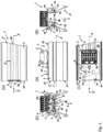
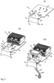
- the figures show different embodiments of an elongated luminaire 1 according to the invention as well as a luminaire system 100 equipped therewith and components thereof.
- luminaires 1 Especially in the Fig. 1 and 2 - but also in the Fig. 18, 19 , 26 and 27 - luminaires 1 according to the present invention are shown.
- the elongated luminaire 1 according to the invention extends along a longitudinal axis X, as is shown in particular in the Fig. 1 , 2 , 19 and 27 shown.
- the lamp 1 has a lamp carrier 2 with a rear side 20 and a front side 21.
- the lamp carrier 2 extends longitudinally with respect to the longitudinal axis X between two axially opposite end faces 22, as can be seen in particular from the Fig. 1 is evident.
- the lamp 1 has an elongated light source 3 for emitting light at least over the front side 21 of the lamp carrier 2; see for example a main light emission direction H in the Fig. 1 , 2 , 18, 19 , 26 and 27 .
- the elongated light source 3 has at least one LED module 3 or forms the same (see Fig. 2E and 26 ).
- the LED module 3 preferably has an elongated circuit board 30 and at least one LED 31 arranged thereon.
- the LEDs 31 are preferably arranged in one or more preferably aligned parallel to the longitudinal axis X rows are provided on the circuit board 30.
- the luminaire 1 further comprises a support plate 4 for fastening current-carrying luminaire components 5.
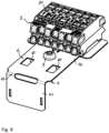
- the support plate 4 is particularly suitable for the Fig. 1 and 2 and 4 to 19 are visible.
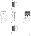
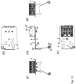
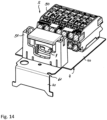
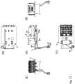
- the current-carrying luminaire components 5 can, for example, be a connection terminal 50 (cf. Fig. 1 , 2 , 5II , 6-19 ) and/or a strain relief 51 (cf. Fig. 5III , 14-17 ) for passing through an electrical cable and/or a status LED 52 (cf. Fig. 5II , 10-13 , 16-19 ) and the like.
- the status LED 52 can be already wired, as shown in the Fig. 5II , 12 , 13 , 16-19
- the above-mentioned current-carrying luminaire components 5 are particularly shown in the Fig. 5II , 16 and 17 shown in combination on the support plate.
- the lamp 1 can therefore preferably have these current-carrying lamp components 5.
- the current-carrying lamp components 5 can be or are attached directly to the support plate 4; this is preferably detachable, as can also be seen from the figures.
- the support plate 4 can have fastening structures 6 for - preferably detachable - fastening of the current-carrying luminaire components 5.
- the fastening structures 6 can have through-openings 60 and/or recesses 61 in the support plate 4, which are preferably formed by separation processes in the support plate 4.
- the current-carrying luminaire components 5 can preferably have structures or elements corresponding to the fastening structures 6 for (releasable) fastening to/on the support plate 4.
- These structures can have locking structures 53, 54.
- these locking structures can have a locking pin 53, as is shown for the connection terminal 50, for example, in Fig. 2E, 7 , 9 , 11 , 13 , 15 and 17
- the locking pin 53 can then, for example, engage or snap into a round through-opening 60 of the support plate 4.
- the locking structures can also have other locking hooks 54, as is the case for the strain relief 51, for example in the Fig. 15 and 17 can be seen.
- the locking structures can then, for example, engage or lock into a rectangular through-opening 60 of the support plate 4 in the embodiments shown here.
- the status LED 52 has, for example, a fastening structure 55 as an element corresponding to the fastening structures 6.
- This fastening structure 55 can have a retaining hook or have a holding wire which holds the light source 56 of the status LED 52 at one end with a positioning section 57 and is fastened to the support plate 4 at the other end.
- the other end has, for example, a hook section 58 with which the fastening structure 55 is hooked into one of the through openings 60 in the support plate 4.
- the fastening structure 55 also has a clamping section 59 between the light source 56 and the hook section 58, with which the fastening structure 55 hooked into the support plate 4 with the hook section 58 can be clamped at another point on the support plate 4 and thus fixed in its position.
- the clamping section 59 is guided into a recess 61, and the fastening structure 55 is thus clamped between the through opening 60 on the one hand and the recess 61 on the other.
- the fastening structure 55 can preferably be hung or clamped into the fastening structures 60, 61 accordingly in order to securely hold the status LED 52 in a defined position - here, for example, directed towards the front 21 of the lamp 1.
- the status LED 52 can be positioned, for example, directly behind a lamp cover 108 in order to be visible from the outside when required (i.e. when the light source 56 is in operation).
- the support plate 4 is preferably made in one piece as a stamped and bent part from a sheet material B, as shown by way of example in the Fig. 3 shown.
- a sheet material B is shown after a punching step in which the structural sections (for example the fastening structures 6) and the basic contour of the support sheet 4 have already been introduced.
- the support sheet is bent into the desired shape, as shown for example in the Fig. 4 shown and described below.
- the support plate 4 can be provided with a note. This can, for example, be printed on the support plate 4, glued on or, as shown here, introduced as an embossing P directly into the support plate 4. In this way, for example, safety instructions or operating instructions (e.g. for the correct connection of conductors or other components) can be provided directly on the support plate 4.
- the support plate 4 can have an L-shape; here in a side view or in a longitudinal section view.
- the lamp carrier 2 has on its front side 21 (in the figures mentioned, the lower side) a holding section 7 for supporting the light source 3.
- the lamp carrier 2 further has on at least one of its End faces 22 have an open insertion region 70 of the holding section 7, via which the lighting means 3 can be guided into the holding section 7 in an insertion direction E oriented parallel to the longitudinal axis X, in order to be received therein in a form-fitting manner perpendicular to the longitudinal axis X.
- the holding section 7 can have a support section 71 which supports the received lighting means 3 on both sides of the longitudinal axis X.
- the holding section 7 or its support section 71 preferably has U-shaped rail sections 72 which are open towards one another on both sides of the longitudinal axis X for receiving the lighting means 3.
- the two rail sections 72 which are directed towards one another here thus delimit a receiving space on both sides for receiving the lighting means 3 between them.
- the lamp 1 can also have an elongated optical element 8 for influencing the light emitted by the lamp 3.
- the optical element 8 can for this purpose have, for example, lenses 80 and/or further optical sections such as diffuser sections and the like.
- the lamp carrier 2 is then preferably further designed such that the optical element 8 can be inserted longitudinally over the insertion region 70 in the insertion direction E in a sliding manner into the holding section 7 in order to be supported therein in a form-fitting manner perpendicular to the longitudinal axis X and to be received in a light path of the light emitted by the lamp 3.
- the holding section 7 can then preferably have a further support section 73 which supports the received optical element 8 on both sides of the longitudinal axis X, wherein the further support section 73 is preferably arranged offset with respect to the support section 71 towards the front side 21, as is particularly shown in Fig. 2E, 26 and 27 can be seen.
- the holding section 7 or its (further) support sections 73 can then also have U-shaped rail sections 74 on both sides of the longitudinal axis X and open towards each other for receiving the optical element 8.
- the two rail sections 74 directed towards each other here thus delimit a further receiving space on both sides for receiving the light source 3 between them.
- the further receiving space can, as shown here, directly adjoin the receiving space delimited by the rail sections 72, so that they preferably form a continuous space in which the light source 3 and the optical element 8 can be arranged; in particular arranged one behind the other with respect to the main light emission direction H.
- the rail sections 72, 74 preferably each extend parallel to the longitudinal axis X and particularly preferably between the two end faces 22. In a preferred embodiment not shown here, it is conceivable that the rail sections 72, 74 each have rail subsections distributed along the longitudinal axis X.
- two parallel longitudinal edges 32 of the circuit board 30 preferably serve for supporting reception in the holding section 7.
- the support plate 4 has a fastening section 40 with which the support plate 4 can be fastened to the rear side 20 of the lamp carrier 2 or is fastened here.
- the support plate 4 can be detachably connected to the lamp body 2, preferably by means of a screw 9 shown here.
- the support plate 4 and with it all its functions and preferably also the current-carrying lamp components 5 can be fastened with just one fastening means (here a central fastening screw 9).
- the support plate 4 and the lamp carrier 2 each have integrally formed fastening structures which make it possible to fasten the support plate 4 to the lamp carrier 2 without separate fastening means. Other known fastening options are also conceivable.
- the fastening section 40 preferably extends in a plane, as can be seen for example from the Fig. 4 is evident.
- the fastening section 40 can have any contour that is suitable for the intended purpose.
- Fig. 6 and 8 Two different contours of the fastening section 40 are shown as examples.
- the fastening section 40 of the support plate 4 in particular has the fastening structures 6.
- the current-carrying luminaire components 5 can preferably be fastened or attached directly to the fastening section 40 - more preferably via its fastening structures 6 - and this is particularly preferably detachable.
- the support plate 4 further comprises a blocking section 41 formed integrally with the fastening section 40.
- the blocking section 41 can also preferably extend in one plane, as can the Fig. 4 Likewise, the blocking section 41 can have any contour that is suitable for the intended purpose is suitable. In the Fig. 6 and 8 Two different contours of the blocking section 41 are shown as examples.
- the blocking section 41 extends at least partially in front of the insertion area 70 such that the light source 3 accommodated in the holding section 7 and possibly also the optical element 8 accommodated in the holding section 7 is/are secured against sliding out of the holding section 7 via the insertion area 70 against the insertion direction E.
- the blocking section 41 can preferably extend in front of the entire insertion area 7 when the support plate 4 is fastened to the rear side 20 of the lamp carrier 2 above the fastening section 40.
- the blocking section preferably extends at least completely in front of the receiving space that accommodates the lamp 3 and also partially in front of the further receiving space that accommodates the optical element 8. In this way, at least the lamp 3 that carries electrical current during operation can be accommodated in the lamp carrier 2 in a way that is safely protected from contact.
- the blocking section 41 and the fastening section 40 can extend away from each other at an angle to each other; here preferably enclose a right angle ⁇ , as is particularly the case with the Fig. 4A can be seen.
- the blocking section 41 can preferably extend from a front edge 42, preferably a narrow side, of the fastening section 40, as is also the case with the Fig. 4 can be seen.
- the blocking section 41 can extend from the fastening section 40 to the front side 21 of the lamp carrier 2.
- the blocking section 41 can preferably have a projection section 43 at an end distal to the fastening section 40, which extends in front of a part of the insertion area 70 when the support plate 4 is fastened to the rear side 20 of the lamp carrier 2 via the fastening section 40, preferably at least partially in front of the further receiving space or the further support section 73 and/or in front of the rail sections 72, 74 or - as shown here - into the rail sections 72, 74.
- the projection sections 43 are laterally flared out in a wing-like manner with respect to the longitudinal axis X, and in the direction of the longitudinal axis X, they only cover the outer, front-side edge regions of the optical element 8 in order to effectively secure the optical element 8 in the holding section 7, while at the same time the light output is impaired as little as possible by the blocking section 41.
- the present invention is further directed to a lighting system 100 which, in addition to the previously described lighting 1, also has an elongated lighting support rail 101 for receiving the lighting 1.
- the elongated lighting support rail 101 is provided as an elongated, U-shaped profile element 101.
- the profile element or the lighting support rail 101 preferably has two lateral side legs 103 and a connecting leg 104 connecting them at the back.
- the lighting support rail 101 defines an interior space I in which the lighting 1 is completely accommodated.
- the lighting support rail 101 can have structural sections 105 directed towards its interior space I or projecting into the interior space I, which can preferably be used to attach the lighting 1 and/or other elements.
- the lamp 1 is preferably provided with its main light emission direction H directed towards the opening 102 defined by the lamp support rail 101 or here its U-profile, in order to emit the light emitted by the lamp 1 for illumination via the opening 102.
- optical lamp elements 108 can be provided, such as here, for example, a simple lamp cover or also a diffuser plate or also a lens or lens plate and the like.
- the light carrier 2 can have light-directing elements 23 on its front side 21, such as a reflector here.
- the light-directing elements 23 are here, for example, formed integrally with the light carrier 2.
- the light-directing elements 23 serve to provide a defined light direction of the light source 3 supported in the holding section 7.
- the lighting system 100 can also have a retaining spring 10 with a fastening leg 11 for fastening to the lighting support 2 and at least one and here two (preferably opposite with respect to the fastening leg 11) locking legs 12 for lockingly receiving the lighting 1 in the lighting support rail 101 - here for example via the structural sections 105.
- the retaining spring 10 can be formed integrally in one piece with the support plate 4. wherein the fastening section 40 then preferably has or forms the fastening leg 11.
- the retaining spring 10 also forms an independent part of the present invention, as described in more detail below.
- the retaining spring 10 is made in one piece from a spring steel.
- the retaining spring 10 can be manufactured in a stamping and bending process.
- the Fig. 20 to 25 show two embodiments of a retaining spring 10 according to the invention (cf. Fig. 20 , 22 , 24, 25 ) or stamped parts S for producing a corresponding retaining spring 10 after a stamping process (and embossing process) and before a corresponding bending process (cf. Fig. 21 and 23 ).
- the retaining spring 10 has the fastening leg 11, which here extends longitudinally along an extension axis Y.
- the retaining spring 10 also has two locking legs 12 that extend axially on both sides of the fastening leg 11 at an angle to the same side with respect to the extension axis Y.
- the locking legs 12 have a locking contour 13, by means of which the retaining spring 10 can be locked in the luminaire support rail 101 or with its structural sections 105, for example, in order to fasten a component fastened via the fastening leg 11 (here the luminaire 1 or its luminaire support 2) in a locking manner. Since the fastening leg 11 can be fastened to the component 1/2 to be fastened, the fastening leg 11 then preferably forms a counter bearing for a resilient pivoting out of the locking legs 12 or their locking contours, which can thus act as detents.
- stabilizing embossings 14 can preferably be provided in order to improve the spring force of the locking legs 12 for securing against the lamp carrier 2.
- the stabilizing embossings 14 act here as a type of stiffening structure.
- the fastening leg 11 can have a through hole 15, which is intended to accommodate a screw shaft 91 of a Fig. 26 and 27 shown fastening screw 90 for fastening the retaining spring 10 - here, for example, to the lamp 1 or its lamp carrier 2.
- the fastening leg 11 further has a slot 16 extending away from the through-opening 15.
- this slot 16 is designed as a cross slot.
- the fastening leg 11 has an embossing 17 in the area of the slot 16, which is provided in such a way that an underside of a screw head 92 of a fastening screw 90 received with its screw shaft 91 in the through hole 15 rests on the slotted embossing 17 when the retaining spring 10 is fastened, as can be seen from the Fig. 26 and 27 can be seen.
- the embossing 17 is preferably provided on a side 18 of the fastening leg 11 facing away from the locking legs 12.
- the fastening leg 11 can have flank sections 19 protruding on both sides with respect to the extension axis Y and in the same direction as the embossing 17, which flank sections 19, together with the fastening leg 11, have a receiving space R for receiving the screw head 92 of the fastening screw 90 received with its screw shaft 91 in the through opening 15.
- the lighting system 100 equipped with the retaining spring 10 or the lamp 1 equipped therewith preferably also has the aforementioned fastening screw 90 for fastening the retaining spring 10 to the lamp body 2, as is particularly the case with Fig. 26 and 27 can be seen.
- the retaining spring 10 can then preferably be designed as described above.
- the fastening leg 11 then has the through-opening for receiving the screw shaft 91 of the fastening screw 90.
- the fastening leg then in turn has the slot 16 extending away from the through-opening 15.
- the fastening leg 11 then in turn has the embossing 17 in the area of the slot 16, which is provided in such a way that the underside of the screw head 92 of the fastening screw 90, which has its screw shaft 91 received in the through-opening 15, rests on the slotted embossing 17 when the retaining spring 10 is attached, as well as the Fig. 26 and 27 can be seen.
- the underside of the screw head 92 can preferably have a lower head toothing (not shown), with which it then rests on the slotted embossing 17, whereby in conjunction with the slotted embossing 17 a particularly high tightening torque of the screw 90 can then be achieved.
Landscapes
- Engineering & Computer Science (AREA)
- General Engineering & Computer Science (AREA)
- Fastening Of Light Sources Or Lamp Holders (AREA)
- Clamps And Clips (AREA)
Applications Claiming Priority (1)
| Application Number | Priority Date | Filing Date | Title |
|---|---|---|---|
| DE102023109448.3A DE102023109448A1 (de) | 2023-04-14 | 2023-04-14 | Leuchte mit Tragblech |
Publications (3)
| Publication Number | Publication Date |
|---|---|
| EP4459178A2 true EP4459178A2 (fr) | 2024-11-06 |
| EP4459178A3 EP4459178A3 (fr) | 2025-01-08 |
| EP4459178B1 EP4459178B1 (fr) | 2025-06-18 |
Family
ID=90545097
Family Applications (1)
| Application Number | Title | Priority Date | Filing Date |
|---|---|---|---|
| EP24167318.5A Active EP4459178B1 (fr) | 2023-04-14 | 2024-03-28 | Lampe avec plaque de support |
Country Status (2)
| Country | Link |
|---|---|
| EP (1) | EP4459178B1 (fr) |
| DE (2) | DE102023109448A1 (fr) |
Families Citing this family (1)
| Publication number | Priority date | Publication date | Assignee | Title |
|---|---|---|---|---|
| DE202024107366U1 (de) * | 2024-12-18 | 2026-05-13 | Zumtobel Lighting Gmbh | Leuchte mit einem Leuchtenträger |
Family Cites Families (4)
| Publication number | Priority date | Publication date | Assignee | Title |
|---|---|---|---|---|
| DE102013226950A1 (de) * | 2013-12-20 | 2015-06-25 | H4X E.U. | Profilleuchtensystem und Montageverfahren dafür |
| US10253956B2 (en) * | 2015-08-26 | 2019-04-09 | Abl Ip Holding Llc | LED luminaire with mounting structure for LED circuit board |
| US10473298B1 (en) * | 2018-05-08 | 2019-11-12 | Nicor, Inc | Architectural linear luminaire |
| DE202019107217U1 (de) * | 2019-12-23 | 2021-03-24 | Zumtobel Lighting Gmbh | Geräteträger sowie Leuchte mit Geräteträger |
-
2023
- 2023-04-14 DE DE102023109448.3A patent/DE102023109448A1/de active Pending
-
2024
- 2024-03-28 EP EP24167318.5A patent/EP4459178B1/fr active Active
- 2024-03-28 DE DE202024107379.7U patent/DE202024107379U1/de active Active
Also Published As
| Publication number | Publication date |
|---|---|
| EP4459178B1 (fr) | 2025-06-18 |
| DE202024107379U1 (de) | 2025-01-22 |
| DE102023109448A1 (de) | 2024-10-17 |
| EP4459178A3 (fr) | 2025-01-08 |
Similar Documents
| Publication | Publication Date | Title |
|---|---|---|
| DE4001389C2 (de) | Fahrzeugscheinwerfer mit universeller Befestigungsmöglichkeit in verschiedenen Fahrzeugen | |
| DE102007004545A1 (de) | Elektrische Anschlussklemme | |
| AT12549U1 (de) | Vorrichtung zum befestigen und kontaktieren eines leuchtmittels und/oder eines leuchtmoduls, sowie leuchte | |
| DE102007038788B4 (de) | Leuchtmodul für eine Halbleiterlichtquellen-Leuchte und Halbleiterlichtquellen-Leuchte | |
| EP4459178B1 (fr) | Lampe avec plaque de support | |
| EP3114400B1 (fr) | Luminaire ou ensemble lumineux comprenant un élément support allongé et un module lumineux fixé de manière libérable | |
| DE102012022082B4 (de) | Scheinwerfer mit Blende für Fahrzeuge | |
| DE102019109676A1 (de) | Haltefeder für Leuchte | |
| EP3608588B1 (fr) | Ressort de maintien pour luminaire | |
| DE102011083993B4 (de) | Lichtband | |
| EP3426975B1 (fr) | Dispositif d'éclairage pour éclairage uniforme | |
| DE102009009496B4 (de) | Betriebsgerät für Leuchtmittel | |
| AT17667U1 (de) | Geräteträger sowie Leuchte mit Geräteträger | |
| EP0947765B1 (fr) | Dispositif de fixation d'une armature lumineuse encastrée | |
| WO2021228627A1 (fr) | Système de ventilateur pour un phare d'un véhicule à moteur, phare et véhicule à moteur | |
| EP4477942B1 (fr) | Lampe suspendue avec élément de sécurité | |
| EP2175188A1 (fr) | Eclairage | |
| DE10234459B4 (de) | Verbindungselement zum Befestigen eines optischen Leuchtenbauteils an einer Leuchte und Leuchte | |
| EP1047574A1 (fr) | Systeme d'eclairage pour vehicules | |
| EP4538592B1 (fr) | Élément de raccordement pour moyen d'éclairage à del | |
| EP3757448B1 (fr) | Ressort de maintien pour boîtiers de luminaire | |
| EP4589195A1 (fr) | Unité de support de luminaire et luminaire équipé de celle-ci | |
| EP4296562A1 (fr) | Unité d'éclairage allongée et système de plafond équipé de celle-ci | |
| EP0981722A1 (fr) | Systeme de mesure | |
| EP2263292A1 (fr) | Dispositif de décharge de traction |
Legal Events
| Date | Code | Title | Description |
|---|---|---|---|
| REG | Reference to a national code |
Ref country code: DE Ref legal event code: R138 Ref document number: 202024107379 Country of ref document: DE Free format text: GERMAN DOCUMENT NUMBER IS 502024000070 |
|
| PUAI | Public reference made under article 153(3) epc to a published international application that has entered the european phase |
Free format text: ORIGINAL CODE: 0009012 |
|
| STAA | Information on the status of an ep patent application or granted ep patent |
Free format text: STATUS: THE APPLICATION HAS BEEN PUBLISHED |
|
| AK | Designated contracting states |
Kind code of ref document: A2 Designated state(s): AL AT BE BG CH CY CZ DE DK EE ES FI FR GB GR HR HU IE IS IT LI LT LU LV MC ME MK MT NL NO PL PT RO RS SE SI SK SM TR |
|
| PUAL | Search report despatched |
Free format text: ORIGINAL CODE: 0009013 |
|
| AK | Designated contracting states |
Kind code of ref document: A3 Designated state(s): AL AT BE BG CH CY CZ DE DK EE ES FI FR GB GR HR HU IE IS IT LI LT LU LV MC ME MK MT NL NO PL PT RO RS SE SI SK SM TR |
|
| RIC1 | Information provided on ipc code assigned before grant |
Ipc: F21Y 103/10 20160101ALN20241202BHEP Ipc: F21Y 115/10 20160101ALN20241202BHEP Ipc: F21V 21/02 20060101ALI20241202BHEP Ipc: F21V 15/01 20060101ALI20241202BHEP Ipc: F21S 4/28 20160101ALI20241202BHEP Ipc: F21V 23/06 20060101ALI20241202BHEP Ipc: F21V 19/00 20060101AFI20241202BHEP |
|
| STAA | Information on the status of an ep patent application or granted ep patent |
Free format text: STATUS: REQUEST FOR EXAMINATION WAS MADE |
|
| 17P | Request for examination filed |
Effective date: 20250116 |
|
| GRAP | Despatch of communication of intention to grant a patent |
Free format text: ORIGINAL CODE: EPIDOSNIGR1 |
|
| STAA | Information on the status of an ep patent application or granted ep patent |
Free format text: STATUS: GRANT OF PATENT IS INTENDED |
|
| INTG | Intention to grant announced |
Effective date: 20250311 |
|
| RIC1 | Information provided on ipc code assigned before grant |
Ipc: F21Y 103/10 20160101ALN20250228BHEP Ipc: F21Y 115/10 20160101ALN20250228BHEP Ipc: F21V 21/02 20060101ALI20250228BHEP Ipc: F21V 15/01 20060101ALI20250228BHEP Ipc: F21S 4/28 20160101ALI20250228BHEP Ipc: F21V 23/06 20060101ALI20250228BHEP Ipc: F21V 19/00 20060101AFI20250228BHEP |
|
| GRAS | Grant fee paid |
Free format text: ORIGINAL CODE: EPIDOSNIGR3 |
|
| GRAA | (expected) grant |
Free format text: ORIGINAL CODE: 0009210 |
|
| STAA | Information on the status of an ep patent application or granted ep patent |
Free format text: STATUS: THE PATENT HAS BEEN GRANTED |
|
| P01 | Opt-out of the competence of the unified patent court (upc) registered |
Free format text: CASE NUMBER: APP_21123/2025 Effective date: 20250505 |
|
| AK | Designated contracting states |
Kind code of ref document: B1 Designated state(s): AL AT BE BG CH CY CZ DE DK EE ES FI FR GB GR HR HU IE IS IT LI LT LU LV MC ME MK MT NL NO PL PT RO RS SE SI SK SM TR |
|
| REG | Reference to a national code |
Ref country code: GB Ref legal event code: FG4D Free format text: NOT ENGLISH |
|
| REG | Reference to a national code |
Ref country code: CH Ref legal event code: EP |
|
| REG | Reference to a national code |
Ref country code: DE Ref legal event code: R096 Ref document number: 502024000070 Country of ref document: DE |
|
| REG | Reference to a national code |
Ref country code: CH Ref legal event code: EP |
|
| REG | Reference to a national code |
Ref country code: IE Ref legal event code: FG4D Free format text: LANGUAGE OF EP DOCUMENT: GERMAN |
|
| PG25 | Lapsed in a contracting state [announced via postgrant information from national office to epo] |
Ref country code: FI Free format text: LAPSE BECAUSE OF FAILURE TO SUBMIT A TRANSLATION OF THE DESCRIPTION OR TO PAY THE FEE WITHIN THE PRESCRIBED TIME-LIMIT Effective date: 20250618 |
|
| REG | Reference to a national code |
Ref country code: LT Ref legal event code: MG9D |
|
| PG25 | Lapsed in a contracting state [announced via postgrant information from national office to epo] |
Ref country code: GR Free format text: LAPSE BECAUSE OF FAILURE TO SUBMIT A TRANSLATION OF THE DESCRIPTION OR TO PAY THE FEE WITHIN THE PRESCRIBED TIME-LIMIT Effective date: 20250919 Ref country code: NO Free format text: LAPSE BECAUSE OF FAILURE TO SUBMIT A TRANSLATION OF THE DESCRIPTION OR TO PAY THE FEE WITHIN THE PRESCRIBED TIME-LIMIT Effective date: 20250918 |
|
| PG25 | Lapsed in a contracting state [announced via postgrant information from national office to epo] |
Ref country code: BG Free format text: LAPSE BECAUSE OF FAILURE TO SUBMIT A TRANSLATION OF THE DESCRIPTION OR TO PAY THE FEE WITHIN THE PRESCRIBED TIME-LIMIT Effective date: 20250618 |
|
| PG25 | Lapsed in a contracting state [announced via postgrant information from national office to epo] |
Ref country code: HR Free format text: LAPSE BECAUSE OF FAILURE TO SUBMIT A TRANSLATION OF THE DESCRIPTION OR TO PAY THE FEE WITHIN THE PRESCRIBED TIME-LIMIT Effective date: 20250618 |
|
| PG25 | Lapsed in a contracting state [announced via postgrant information from national office to epo] |
Ref country code: RS Free format text: LAPSE BECAUSE OF FAILURE TO SUBMIT A TRANSLATION OF THE DESCRIPTION OR TO PAY THE FEE WITHIN THE PRESCRIBED TIME-LIMIT Effective date: 20250918 |
|
| REG | Reference to a national code |
Ref country code: NL Ref legal event code: MP Effective date: 20250618 |
|
| PG25 | Lapsed in a contracting state [announced via postgrant information from national office to epo] |
Ref country code: LV Free format text: LAPSE BECAUSE OF FAILURE TO SUBMIT A TRANSLATION OF THE DESCRIPTION OR TO PAY THE FEE WITHIN THE PRESCRIBED TIME-LIMIT Effective date: 20250618 |
|
| PG25 | Lapsed in a contracting state [announced via postgrant information from national office to epo] |
Ref country code: NL Free format text: LAPSE BECAUSE OF FAILURE TO SUBMIT A TRANSLATION OF THE DESCRIPTION OR TO PAY THE FEE WITHIN THE PRESCRIBED TIME-LIMIT Effective date: 20250618 |
|
| PG25 | Lapsed in a contracting state [announced via postgrant information from national office to epo] |
Ref country code: PT Free format text: LAPSE BECAUSE OF FAILURE TO SUBMIT A TRANSLATION OF THE DESCRIPTION OR TO PAY THE FEE WITHIN THE PRESCRIBED TIME-LIMIT Effective date: 20251020 |
|
| PG25 | Lapsed in a contracting state [announced via postgrant information from national office to epo] |
Ref country code: IS Free format text: LAPSE BECAUSE OF FAILURE TO SUBMIT A TRANSLATION OF THE DESCRIPTION OR TO PAY THE FEE WITHIN THE PRESCRIBED TIME-LIMIT Effective date: 20251018 |
|
| PG25 | Lapsed in a contracting state [announced via postgrant information from national office to epo] |
Ref country code: SM Free format text: LAPSE BECAUSE OF FAILURE TO SUBMIT A TRANSLATION OF THE DESCRIPTION OR TO PAY THE FEE WITHIN THE PRESCRIBED TIME-LIMIT Effective date: 20250618 |
|
| PG25 | Lapsed in a contracting state [announced via postgrant information from national office to epo] |
Ref country code: CZ Free format text: LAPSE BECAUSE OF FAILURE TO SUBMIT A TRANSLATION OF THE DESCRIPTION OR TO PAY THE FEE WITHIN THE PRESCRIBED TIME-LIMIT Effective date: 20250618 |
|
| PG25 | Lapsed in a contracting state [announced via postgrant information from national office to epo] |
Ref country code: PL Free format text: LAPSE BECAUSE OF FAILURE TO SUBMIT A TRANSLATION OF THE DESCRIPTION OR TO PAY THE FEE WITHIN THE PRESCRIBED TIME-LIMIT Effective date: 20250618 |
|
| PG25 | Lapsed in a contracting state [announced via postgrant information from national office to epo] |
Ref country code: EE Free format text: LAPSE BECAUSE OF FAILURE TO SUBMIT A TRANSLATION OF THE DESCRIPTION OR TO PAY THE FEE WITHIN THE PRESCRIBED TIME-LIMIT Effective date: 20250618 |
|
| PG25 | Lapsed in a contracting state [announced via postgrant information from national office to epo] |
Ref country code: SK Free format text: LAPSE BECAUSE OF FAILURE TO SUBMIT A TRANSLATION OF THE DESCRIPTION OR TO PAY THE FEE WITHIN THE PRESCRIBED TIME-LIMIT Effective date: 20250618 |
|
| PG25 | Lapsed in a contracting state [announced via postgrant information from national office to epo] |
Ref country code: ES Free format text: LAPSE BECAUSE OF FAILURE TO SUBMIT A TRANSLATION OF THE DESCRIPTION OR TO PAY THE FEE WITHIN THE PRESCRIBED TIME-LIMIT Effective date: 20250618 |
|
| PG25 | Lapsed in a contracting state [announced via postgrant information from national office to epo] |
Ref country code: DK Free format text: LAPSE BECAUSE OF FAILURE TO SUBMIT A TRANSLATION OF THE DESCRIPTION OR TO PAY THE FEE WITHIN THE PRESCRIBED TIME-LIMIT Effective date: 20250618 |
|
| PGFP | Annual fee paid to national office [announced via postgrant information from national office to epo] |
Ref country code: DE Payment date: 20260320 Year of fee payment: 3 |
|
| PGFP | Annual fee paid to national office [announced via postgrant information from national office to epo] |
Ref country code: AT Payment date: 20260301 Year of fee payment: 3 |
|
| PG25 | Lapsed in a contracting state [announced via postgrant information from national office to epo] |
Ref country code: IT Free format text: LAPSE BECAUSE OF FAILURE TO SUBMIT A TRANSLATION OF THE DESCRIPTION OR TO PAY THE FEE WITHIN THE PRESCRIBED TIME-LIMIT Effective date: 20250618 |
|
| PGFP | Annual fee paid to national office [announced via postgrant information from national office to epo] |
Ref country code: FR Payment date: 20260323 Year of fee payment: 3 |
|
| PLBE | No opposition filed within time limit |
Free format text: ORIGINAL CODE: 0009261 |
|
| STAA | Information on the status of an ep patent application or granted ep patent |
Free format text: STATUS: NO OPPOSITION FILED WITHIN TIME LIMIT |
|
| REG | Reference to a national code |
Ref country code: CH Ref legal event code: L10 Free format text: ST27 STATUS EVENT CODE: U-0-0-L10-L00 (AS PROVIDED BY THE NATIONAL OFFICE) Effective date: 20260430 |