EP4459193A1 - Hydraulikmodul mit wahlweisen platten und heizvorrichtung mit einem hydraulikmodul - Google Patents
Hydraulikmodul mit wahlweisen platten und heizvorrichtung mit einem hydraulikmodul Download PDFInfo
- Publication number
- EP4459193A1 EP4459193A1 EP24173271.8A EP24173271A EP4459193A1 EP 4459193 A1 EP4459193 A1 EP 4459193A1 EP 24173271 A EP24173271 A EP 24173271A EP 4459193 A1 EP4459193 A1 EP 4459193A1
- Authority
- EP
- European Patent Office
- Prior art keywords
- heating device
- connection
- hydraulic module
- heat exchanger
- plate
- Prior art date
- Legal status (The legal status is an assumption and is not a legal conclusion. Google has not performed a legal analysis and makes no representation as to the accuracy of the status listed.)
- Withdrawn
Links
Images




Classifications
-
- F—MECHANICAL ENGINEERING; LIGHTING; HEATING; WEAPONS; BLASTING
- F24—HEATING; RANGES; VENTILATING
- F24D—DOMESTIC- OR SPACE-HEATING SYSTEMS, e.g. CENTRAL HEATING SYSTEMS; DOMESTIC HOT-WATER SUPPLY SYSTEMS; ELEMENTS OR COMPONENTS THEREFOR
- F24D3/00—Hot-water central heating systems
- F24D3/08—Hot-water central heating systems in combination with systems for domestic hot-water supply
-
- F—MECHANICAL ENGINEERING; LIGHTING; HEATING; WEAPONS; BLASTING
- F24—HEATING; RANGES; VENTILATING
- F24H—FLUID HEATERS, e.g. WATER OR AIR HEATERS, HAVING HEAT-GENERATING MEANS, e.g. HEAT PUMPS, IN GENERAL
- F24H9/00—Details
- F24H9/14—Arrangements for connecting different sections, e.g. in water heaters
- F24H9/142—Connecting hydraulic components
-
- F—MECHANICAL ENGINEERING; LIGHTING; HEATING; WEAPONS; BLASTING
- F24—HEATING; RANGES; VENTILATING
- F24D—DOMESTIC- OR SPACE-HEATING SYSTEMS, e.g. CENTRAL HEATING SYSTEMS; DOMESTIC HOT-WATER SUPPLY SYSTEMS; ELEMENTS OR COMPONENTS THEREFOR
- F24D19/00—Details
- F24D19/10—Arrangement or mounting of control or safety devices
- F24D19/1006—Arrangement or mounting of control or safety devices for water heating systems
- F24D19/1066—Arrangement or mounting of control or safety devices for water heating systems for the combination of central heating and domestic hot water
-
- F—MECHANICAL ENGINEERING; LIGHTING; HEATING; WEAPONS; BLASTING
- F24—HEATING; RANGES; VENTILATING
- F24D—DOMESTIC- OR SPACE-HEATING SYSTEMS, e.g. CENTRAL HEATING SYSTEMS; DOMESTIC HOT-WATER SUPPLY SYSTEMS; ELEMENTS OR COMPONENTS THEREFOR
- F24D2220/00—Components of central heating installations excluding heat sources
- F24D2220/02—Fluid distribution means
- F24D2220/0292—Fluid distribution networks
Definitions
- the invention relates to hydraulic modules that are part of heating devices intended for space heating and/or domestic hot water preparation.
- Connectors are used to connect the heating device to individual circuits for space heating and/or domestic hot water preparation and are connected to a hydraulic module inside the heating device.
- Hydraulic modules are manufactured as separate units, they are built into the heating device and are primarily designed to provide circulation of heat transfer fluid through heat exchangers and to direct heated/cold water to/from the individual circuits by means of a circulating pump and a switch valve.
- the hydraulic module can also supply heat for heating to an external domestic hot water storage tank.
- hydraulic modules implement more and more different functions (bypass function, filling loop, pressure, flow, temperature measurement, safety relief valve, etc.), which makes their design more and more complicated.
- the DE102019215021 A1 document describes a hydraulic module for a heating device for arrangement on a base device forming a heating device, with connecting ducts routed through the hydraulic module for hydraulic connection of the base device to a heat source and/or a heat sink.
- the hydraulic module functions as a hydraulic interface between the heat generator and the heat accumulator on one side, and the heat source and the heat sink on the other side.
- the above described hydraulic module can be prepared for installation in the installation space through pre-assembly and can also be further expanded with additional sub-assemblies.
- the hydraulic module is either arranged on the top side of the base unit or alternatively, it can be spatially arranged between the accumulator module and the heat generator module.
- the hydraulic module is designed so that it can alternatively be spatially separated from the base unit and installed on the wall of the installation room. This solution indeed ensures greater variability compared to the one described in the WO2018202436 A1 document, but it requires a large amount of interconnecting accessories for various combinations of functions and devices.
- the task of the invention is to create a hydraulic module design that ensures easy implementation of functions without structural changes to the basic design, while also minimizing the need for excess connections.
- a hydraulic module comprising a basic body and at least one optional plate.
- the basic body and optional plates are separate structural components that comprise means that enable the basic body and the optional plates to be easily and watertightly interconnected, allowing for straightforward assembly and maintenance of the resulting hydraulic module.
- One structural part constitutes the basic body of the hydraulic module, encompassing interconnections and basic functions necessary across all variants within a specific hydraulic module group. This entails at least one circulation pump and a three-way switch valve for heating circuit switching.
- the optional plate encompasses optional functions required only in certain variants within a specific group of hydraulic modules. It includes, for example, a bypass function, filling loop, flow sensor and other required functions.
- the optional functions depend on whether it is a heating device called “system heating device” - such heating devices produce heat to warm the space and possibly supply hot water to the storage tank - or whether it is a heating device called “combined heating device” - such heating devices produce heat to warm the space and, using a secondary plate heat exchanger, supply heat for domestic hot water preparation.
- the proposed invention allows for the use of the same basic body of the hydraulic module for both system heating devices and combined heating devices.
- the optional plates are designed according to the required functions, and there can be several types of them. It is possible to combine several optional plates to form the final hydraulic module.
- the optional plates are hydraulically connectable to the basic body of the hydraulic module and also connectable each to other. They are also stackable, for easy mechanical fixation.
- the integration of functions (components) into different optional plates is innovative.
- Optional plates can be easily and watertightly mounted to the basic body of the hydraulic module. In the case of combined heating devices, the optional plates are mounted between the basic body of the hydraulic module and the plate heat exchanger.
- Hydraulic module with an optional plate 80 for a system heating device
- Fig. 1 and 2 depict a lateral view and a cross-section of an example optional plate 80 for a system heating device which provides the function of bypass in the hydraulic module.
- the optional plate 80 is made of suitable plastic material, it has a cuboid shape, and it integrates interconnecting ducts and connection points.
- the plate is reinforced with ribs 3.
- the bypass valve 13 is inserted into the connection duct on the optional plate 80 and is secured with a clip 4.
- the bypass valve 13 is connected to the bypass duct 7.
- FIG. 7 depicts an exemplary system heating device 100 with a primary heat exchanger 10, a circulation pump 11, a three-way switch valve 12, and a bypass valve 13, wherein the bypass valve 13 is arranged on the optional plate 80, and the circulation pump 11 and three-way switch valve 12 are arranged on the basic body 1 of the hydraulic module.
- the basic body 1 of the hydraulic module is equipped with connectors 17,170 to/from the heating water circuit and 19,190 to/from the external storage tank.
- Connectors 17 for the output of hot water intended for space heating and 170 (return from heating) connect the heating device to the radiator system (or other heat exchangers) in the heated space (not depicted).
- Connectors 19 (to the external tank) and 190 (from the external tank) connect the heating device to the heat exchanger in the external water storage tank (not depicted).
- connectors 19 and 190 can be sealed with a plug 6.
- Connectors 19 and 190 can be advantageously interconnected to provide the bypass function.
- the optional plate 80 can be hydraulically connected to the basic body 1 of the hydraulic module of the heating device and is equipped with connection points A, B, C, D.
- Connection point A is a connection to the duct supplying heated water from the primary heat exchanger 10.
- Connection point B is a connection to the duct supplying return water to the three-way valve 12.
- Connection point C is a connection to the duct supplying heated water to the heat exchanger in the external storage tank via the connector 19.
- Connection point D is a connection to the duct supplying return water from the external storage tank via the connector 190.
- the heat exchanger in the external water storage tank is a coil.
- Hydraulic module with an optional plate 90 for a combined heating device
- Fig. 3 and Fig. 4 depict a lateral view and a cross-section of an example optional plate 90 for a combined heating device, which provides several functions in the hydraulic module.
- the optional plate 90 is made of suitable plastic material, it has a cuboid shape, and it integrates interconnecting ducts and connection points.
- the plate is reinforced with ribs 3.
- the bypass valve 13 is inserted into the connection duct on the optional plate 90 and is secured with a clip 4.
- the optional plate 90 also includes connecting ducts and connectors for the filling loop 14, temperature sensor 15, and flow sensor 16.
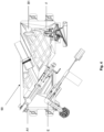
- Fig. 5 depicts the assembly of a hydraulic module consisting of the optional plate 90 for a combined heating device and the basic body 1 of the hydraulic module.
- FIG. 8 depicts the connection of an exemplary combined heating device 200 with a primary heat exchanger 10, a circulation pump 11, a three-way switch valve 12, and a bypass valve 13.
- the bypass valve 13 is connected to the bypass duct 7.
- Connectors 17 (to the heating water circuit) and 170 (return from the heating water circuit) connect the heating device to the radiator system (or other heat exchangers) in the heated space (not depicted).
- Connector 180 (return from the domestic hot water circuit) is connected to the flow sensor 16.
- Connector 18 (hot water outlet to the domestic hot water circuit) is connected to the temperature sensor 15 and to the filling loop 14.
- the optional plate 90 for a combined heating device can be hydraulically connected to the basic body 1 of the hydraulic module of the heating device and is equipped with connection points A1, B1, E, F.
- Connection point A1 is a connection to the duct supplying heated water from the primary heat exchanger 10.
- Connection point B1 is a connection to the duct supplying return water to the three-way switch valve 12.
- Connection point E is a connection to the duct supplying heated domestic water from the plate heat exchanger 5 to the domestic hot water circuit via the connector 18.
- Connection point F is a connection to the duct supplying cold domestic water to the plate heat exchanger 5 via the connector 180.
- Hydraulic module with an optional plate 80 for a system heating device and with an optional plate 90 for a combined heating device
- Fig. 6 shows the connection of two different optional plates (80, 90) on top of each other.
- the optional plates (80, 90) are stacked, hydraulically interconnected and mechanically joined by brackets (2) and screws (not depicted).
- the optional plates (80, 90) allow for integrating various combinations of functions, especially previously unused functions, facilitating the future design change of the hydraulic module.
- Attaining variability simply requires adhering to the dimensions of the optional plates and the placement of the connection points.
- connection points are made as recessed holes to accommodate O-ring seals, but other methods of connection are not limited by this.
- the optional plates enable simple production and assembly of hydraulic modules, particularly offering a high level of variability in functions provided by heating devices equipped with such hydraulic modules.
Landscapes
- Engineering & Computer Science (AREA)
- Physics & Mathematics (AREA)
- Thermal Sciences (AREA)
- Chemical & Material Sciences (AREA)
- Combustion & Propulsion (AREA)
- Mechanical Engineering (AREA)
- General Engineering & Computer Science (AREA)
- Water Supply & Treatment (AREA)
- Fluid-Pressure Circuits (AREA)
- Steam Or Hot-Water Central Heating Systems (AREA)
Applications Claiming Priority (1)
| Application Number | Priority Date | Filing Date | Title |
|---|---|---|---|
| SK66-2023U SK9983Y1 (sk) | 2023-05-02 | 2023-05-02 | Hydraulický modul s voliteľnými doskami a vykurovacie zariadenie vybavené hydraulickým modulom |
Publications (1)
| Publication Number | Publication Date |
|---|---|
| EP4459193A1 true EP4459193A1 (de) | 2024-11-06 |
Family
ID=88649270
Family Applications (1)
| Application Number | Title | Priority Date | Filing Date |
|---|---|---|---|
| EP24173271.8A Withdrawn EP4459193A1 (de) | 2023-05-02 | 2024-04-30 | Hydraulikmodul mit wahlweisen platten und heizvorrichtung mit einem hydraulikmodul |
Country Status (2)
| Country | Link |
|---|---|
| EP (1) | EP4459193A1 (de) |
| SK (1) | SK9983Y1 (de) |
Citations (4)
| Publication number | Priority date | Publication date | Assignee | Title |
|---|---|---|---|---|
| EP1408292A1 (de) * | 2002-10-07 | 2004-04-14 | Nefit Buderus B.V. | Heizgerät |
| EP2148149B1 (de) * | 2008-07-21 | 2018-10-24 | O.T.M.A. S.N.C. di Spaggiari & C. | Hydraulikventilanordnung für wandmontierte Boiler |
| WO2018202436A1 (de) | 2017-05-03 | 2018-11-08 | Vaillant Gmbh | Konstruktionseinheit für das hydraulikmodul |
| DE102019215021A1 (de) | 2019-09-30 | 2021-04-01 | Robert Bosch Gmbh | Heizgerät und Hydraulikmodul |
-
2023
- 2023-05-02 SK SK66-2023U patent/SK9983Y1/sk unknown
-
2024
- 2024-04-30 EP EP24173271.8A patent/EP4459193A1/de not_active Withdrawn
Patent Citations (4)
| Publication number | Priority date | Publication date | Assignee | Title |
|---|---|---|---|---|
| EP1408292A1 (de) * | 2002-10-07 | 2004-04-14 | Nefit Buderus B.V. | Heizgerät |
| EP2148149B1 (de) * | 2008-07-21 | 2018-10-24 | O.T.M.A. S.N.C. di Spaggiari & C. | Hydraulikventilanordnung für wandmontierte Boiler |
| WO2018202436A1 (de) | 2017-05-03 | 2018-11-08 | Vaillant Gmbh | Konstruktionseinheit für das hydraulikmodul |
| DE102019215021A1 (de) | 2019-09-30 | 2021-04-01 | Robert Bosch Gmbh | Heizgerät und Hydraulikmodul |
Also Published As
| Publication number | Publication date |
|---|---|
| SK9983Y1 (sk) | 2024-02-28 |
| SK662023U1 (sk) | 2023-11-08 |
Similar Documents
| Publication | Publication Date | Title |
|---|---|---|
| US20090020270A1 (en) | Apparatus for distributing and controlling a heat carrier | |
| CN113733841B (zh) | 集成式水壶组件及热管理系统 | |
| CN105972260B (zh) | 液压阀 | |
| CN109792228A (zh) | 具有集成电路的用于发电的系统和设备 | |
| GB2480669A (en) | Manifold for a heating or refrigeration system | |
| EP4459193A1 (de) | Hydraulikmodul mit wahlweisen platten und heizvorrichtung mit einem hydraulikmodul | |
| US9726382B2 (en) | Heat exchanger unit having connectors with identical base elements | |
| EP4108998B1 (de) | Monolithische heizstation mit bypass | |
| SK1062017U1 (sk) | Konštrukčná jednotka pre hydraulický modul | |
| KR20150029444A (ko) | 분산형 축열조 및 축열 시스템 | |
| EP1944554A2 (de) | Einheit und Verfahren zur Verteilung von Flüssigkeiten | |
| JP6458541B2 (ja) | 加熱循環回路用熱分配ユニット | |
| JP2014115061A (ja) | 給湯機および弁ユニット | |
| US9366447B2 (en) | Service water heating unit | |
| EP4108997A1 (de) | Verbindungsvorrichtung für eine wärmestation | |
| EP4538612A1 (de) | Verbrennungsgeräteeinheit für ein hybridsystem | |
| EP3084316B1 (de) | Wärmetauschervorrichtung | |
| EP4636321A1 (de) | Verbindungsanordnung für ein wärmesteuerungssystem | |
| LU505389B1 (en) | Method for commissioning a hybrid system | |
| RU2815997C1 (ru) | Универсальная гидрогруппа для настенного котла и способ его переоборудования | |
| CN216203656U (zh) | 供热设备的水路模块、供热设备和连接件 | |
| EP1544551B1 (de) | Wärmetauscher für Heizungsanlagen | |
| CN208983451U (zh) | 组合式壁挂炉采暖热水系统 | |
| EP1965139A2 (de) | Hydraulikaggregat mit zwei sekundären Wärmetauschern für Gasboilersysteme | |
| SK1452016U1 (sk) | Blok pripojovacieho rozhrania |
Legal Events
| Date | Code | Title | Description |
|---|---|---|---|
| PUAI | Public reference made under article 153(3) epc to a published international application that has entered the european phase |
Free format text: ORIGINAL CODE: 0009012 |
|
| STAA | Information on the status of an ep patent application or granted ep patent |
Free format text: STATUS: THE APPLICATION HAS BEEN PUBLISHED |
|
| AK | Designated contracting states |
Kind code of ref document: A1 Designated state(s): AL AT BE BG CH CY CZ DE DK EE ES FI FR GB GR HR HU IE IS IT LI LT LU LV MC ME MK MT NL NO PL PT RO RS SE SI SK SM TR |
|
| STAA | Information on the status of an ep patent application or granted ep patent |
Free format text: STATUS: THE APPLICATION IS DEEMED TO BE WITHDRAWN |
|
| 18D | Application deemed to be withdrawn |
Effective date: 20250507 |