EP4459253A1 - Capteur tactile optique - Google Patents
Capteur tactile optique Download PDFInfo
- Publication number
- EP4459253A1 EP4459253A1 EP23740420.7A EP23740420A EP4459253A1 EP 4459253 A1 EP4459253 A1 EP 4459253A1 EP 23740420 A EP23740420 A EP 23740420A EP 4459253 A1 EP4459253 A1 EP 4459253A1
- Authority
- EP
- European Patent Office
- Prior art keywords
- marker
- tactile sensor
- sensor module
- color
- markers
- Prior art date
- Legal status (The legal status is an assumption and is not a legal conclusion. Google has not performed a legal analysis and makes no representation as to the accuracy of the status listed.)
- Pending
Links
Images


Classifications
-
- G—PHYSICS
- G06—COMPUTING OR CALCULATING; COUNTING
- G06T—IMAGE DATA PROCESSING OR GENERATION, IN GENERAL
- G06T7/00—Image analysis
- G06T7/20—Analysis of motion
- G06T7/246—Analysis of motion using feature-based methods, e.g. the tracking of corners or segments
-
- B—PERFORMING OPERATIONS; TRANSPORTING
- B25—HAND TOOLS; PORTABLE POWER-DRIVEN TOOLS; MANIPULATORS
- B25J—MANIPULATORS; CHAMBERS PROVIDED WITH MANIPULATION DEVICES
- B25J9/00—Program-controlled manipulators
- B25J9/16—Program controls
- B25J9/1694—Program controls characterised by use of sensors other than normal servo-feedback from position, speed or acceleration sensors, perception control, multi-sensor controlled systems, sensor fusion
- B25J9/1697—Vision controlled systems
-
- G—PHYSICS
- G01—MEASURING; TESTING
- G01L—MEASURING FORCE, STRESS, TORQUE, WORK, MECHANICAL POWER, MECHANICAL EFFICIENCY, OR FLUID PRESSURE
- G01L1/00—Measuring force or stress, in general
- G01L1/24—Measuring force or stress, in general by measuring variations of optical properties of material when it is stressed, e.g. by photoelastic stress analysis using infrared, visible light, ultraviolet
-
- G—PHYSICS
- G01—MEASURING; TESTING
- G01L—MEASURING FORCE, STRESS, TORQUE, WORK, MECHANICAL POWER, MECHANICAL EFFICIENCY, OR FLUID PRESSURE
- G01L1/00—Measuring force or stress, in general
- G01L1/24—Measuring force or stress, in general by measuring variations of optical properties of material when it is stressed, e.g. by photoelastic stress analysis using infrared, visible light, ultraviolet
- G01L1/247—Measuring force or stress, in general by measuring variations of optical properties of material when it is stressed, e.g. by photoelastic stress analysis using infrared, visible light, ultraviolet using distributed sensing elements, e.g. microcapsules
-
- G—PHYSICS
- G01—MEASURING; TESTING
- G01L—MEASURING FORCE, STRESS, TORQUE, WORK, MECHANICAL POWER, MECHANICAL EFFICIENCY, OR FLUID PRESSURE
- G01L5/00—Apparatus for, or methods of, measuring force, work, mechanical power, or torque, specially adapted for specific purposes
- G01L5/16—Apparatus for, or methods of, measuring force, work, mechanical power, or torque, specially adapted for specific purposes for measuring several components of force
- G01L5/166—Apparatus for, or methods of, measuring force, work, mechanical power, or torque, specially adapted for specific purposes for measuring several components of force using photoelectric means
-
- G—PHYSICS
- G01—MEASURING; TESTING
- G01L—MEASURING FORCE, STRESS, TORQUE, WORK, MECHANICAL POWER, MECHANICAL EFFICIENCY, OR FLUID PRESSURE
- G01L5/00—Apparatus for, or methods of, measuring force, work, mechanical power, or torque, specially adapted for specific purposes
- G01L5/22—Apparatus for, or methods of, measuring force, work, mechanical power, or torque, specially adapted for specific purposes for measuring the force applied to control members, e.g. control members of vehicles, triggers
-
- G—PHYSICS
- G01—MEASURING; TESTING
- G01L—MEASURING FORCE, STRESS, TORQUE, WORK, MECHANICAL POWER, MECHANICAL EFFICIENCY, OR FLUID PRESSURE
- G01L5/00—Apparatus for, or methods of, measuring force, work, mechanical power, or torque, specially adapted for specific purposes
- G01L5/22—Apparatus for, or methods of, measuring force, work, mechanical power, or torque, specially adapted for specific purposes for measuring the force applied to control members, e.g. control members of vehicles, triggers
- G01L5/226—Apparatus for, or methods of, measuring force, work, mechanical power, or torque, specially adapted for specific purposes for measuring the force applied to control members, e.g. control members of vehicles, triggers to manipulators, e.g. the force due to gripping
- G01L5/228—Apparatus for, or methods of, measuring force, work, mechanical power, or torque, specially adapted for specific purposes for measuring the force applied to control members, e.g. control members of vehicles, triggers to manipulators, e.g. the force due to gripping using tactile array force sensors
-
- G—PHYSICS
- G06—COMPUTING OR CALCULATING; COUNTING
- G06T—IMAGE DATA PROCESSING OR GENERATION, IN GENERAL
- G06T1/00—General purpose image data processing
- G06T1/0014—Image feed-back for automatic industrial control, e.g. robot with camera
-
- G—PHYSICS
- G06—COMPUTING OR CALCULATING; COUNTING
- G06T—IMAGE DATA PROCESSING OR GENERATION, IN GENERAL
- G06T2207/00—Indexing scheme for image analysis or image enhancement
- G06T2207/30—Subject of image; Context of image processing
- G06T2207/30108—Industrial image inspection
-
- G—PHYSICS
- G06—COMPUTING OR CALCULATING; COUNTING
- G06T—IMAGE DATA PROCESSING OR GENERATION, IN GENERAL
- G06T2207/00—Indexing scheme for image analysis or image enhancement
- G06T2207/30—Subject of image; Context of image processing
- G06T2207/30204—Marker
Definitions
- Various embodiments of the disclosure relate to an optical tactile sensor, preferably, to a tactile sensor used in a robot hand.
- a tactile sensor is useful for detecting, recognizing, and/or manipulating objects and is based on contact between the object and the sensor.
- An optical tactile sensor is a tactile sensor that uses a camera to capture the type of contact and slippage between an object and the sensor.
- a camera-based optical tactile sensor may measure the displacement of an elastic part (e.g., gel) and a plurality of markers due to contact with an object using a camera, thereby measuring the force applied to the elastic part.
- Camera-based optical tactile sensors may include a function of capturing external images using a camera in addition to the force measurement.
- OTS optical tactile sensor
- the optical tactile sensor is configured as markers including a plurality of colors and is able to accurately measure the displacement of the marker when capturing an external image.
- An optical tactile sensor module may include a housing, a circuit board disposed inside the housing, an elastic part including a first surface to come into contact with an object, a plurality of markers disposed on the first surface of the elastic part, and a camera unit electrically connected to the circuit board and capturing movements of the markers when the object approaches the first surface of the elastic part, wherein the markers may include a first marker including a first color, and a second marker including a second color different from the first color.
- An electronic device may include an optical tactile sensor module, and a circuit board electrically connected to the optical tactile sensor module, wherein the optical tactile sensor module may include a housing, a circuit board disposed inside the housing, an elastic part including a first surface to come into contact with an object, a plurality of markers disposed on the first surface of the elastic part, and a camera unit electrically connected to the circuit board and capturing movements of the markers when the object approaches the first surface of the elastic part, wherein the markers may include a first marker including a first color, and a second marker including a second color different from the first color.
- the marker may include a plurality of markers having a plurality of colors.
- the markers of the optical tactile sensor may use thermosensitive pigments. Therefore, the colors of the markers using thermosensitive pigments may change into a plurality of colors depending on a plurality of measurable temperature ranges.
- the optical tactile sensor may measure the temperature of an external object when it approaches, and identify whether or not it is in contact with the external object and the contact area thereof.
- the electronic device may be one of various types of electronic devices.
- the electronic devices may include, for example, a portable communication device (e.g., a smartphone), a computer device, a portable multimedia device, a portable medical device, a camera, a wearable device, or a home appliance. According to an embodiment of the disclosure, the electronic devices are not limited to those described above.
- each of such phrases as “A or B,” “at least one of A and B,” “at least one of A or B,” “A, B, or C,” “at least one of A, B, and C,” and “at least one of A, B, or C,” may include any one of, or all possible combinations of the items enumerated together in a corresponding one of the phrases.
- such terms as “1st” and “2nd,” or “first” and “second” may be used to simply distinguish a corresponding component from another, and does not limit the components in other aspect (e.g., importance or order).
- an element e.g., a first element
- the element may be coupled with the other element directly (e.g., wiredly), wirelessly, or via a third element.
- module may include a unit implemented in hardware, software, or firmware, and may interchangeably be used with other terms, for example, “logic,” “logic block,” “part,” or “circuitry”.
- a module may be a single integral component, or a minimum unit or part thereof, adapted to perform one or more functions.
- the module may be implemented in a form of an application-specific integrated circuit (ASIC).
- ASIC application-specific integrated circuit
- Various embodiments as set forth herein may be implemented as software (e.g., the program) including one or more instructions that are stored in a storage medium (e.g., internal memory or external memory) that is readable by a machine (e.g., the electronic device).
- a processor e.g., the processor
- the machine e.g., the electronic device 101
- the one or more instructions may include a code generated by a complier or a code executable by an interpreter.
- the machine-readable storage medium may be provided in the form of a non-transitory storage medium.
- non-transitory simply means that the storage medium is a tangible device, and does not include a signal (e.g., an electromagnetic wave), but this term does not differentiate between where data is semi-permanently stored in the storage medium and where the data is temporarily stored in the storage medium.
- a method may be included and provided in a computer program product.
- the computer program product may be traded as a product between a seller and a buyer.
- the computer program product may be distributed in the form of a machine-readable storage medium (e.g., compact disc read only memory (CD-ROM)), or be distributed (e.g., downloaded or uploaded) online via an application store (e.g., PlayStore TM ), or between two user devices (e.g., smart phones) directly. If distributed online, at least part of the computer program product may be temporarily generated or at least temporarily stored in the machine-readable storage medium, such as memory of the manufacturer's server, a server of the application store, or a relay server.
- CD-ROM compact disc read only memory
- an application store e.g., PlayStore TM
- two user devices e.g., smart phones
- each component e.g., a module or a program of the above-described components may include a single entity or multiple entities, and some of the multiple entities may be separately disposed in different components. According to various embodiments, one or more of the above-described components may be omitted, or one or more other components may be added. Alternatively or additionally, a plurality of components (e.g., modules or programs) may be integrated into a single component. In such a case, according to various embodiments, the integrated component may still perform one or more functions of each of the plurality of components in the same or similar manner as they are performed by a corresponding one of the plurality of components before the integration.
- operations performed by the module, the program, or another component may be carried out sequentially, in parallel, repeatedly, or heuristically, or one or more of the operations may be executed in a different order or omitted, or one or more other operations may be added.
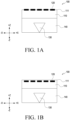
- FIG. 1A and 1B are side views schematically illustrating an optical tactile sensor module 100 according to an embodiment of the disclosure.
- FIG. 2 is a side view schematically illustrating an optical tactile sensor module 100 according to another embodiment of the disclosure.
- FIG. 3 is a diagram illustrating an elastic part 110 viewed from a camera unit 130 and general markers 120 arranged at the elastic part 110 according to a general optical tactile sensor module.
- FIG. 4A is a diagram illustrating an elastic part 110, which does not include a general marker 120, viewed from a camera unit 130 according to a general optical tactile sensor module.
- FIG. 4B is a diagram illustrating a screen captured by a camera unit 130 in the case of FIG. 4A .
- FIG. 5A is a diagram illustrating an elastic part 110 viewed from a camera unit 130 and markers 120 according to various embodiments of the disclosure.
- FIG. 5B is a diagram illustrating a screen captured by a camera unit 130 in the case of FIG. 5A .
- the optical tactile sensor module 100 may include an elastic part 110, general markers 120, a camera unit 130, and a housing 140.
- "X” may indicate the longitudinal direction of the optical tactile sensor module 100.
- “Y” may indicate the width direction of the optical tactile sensor module 100.
- “Z” may indicate the thickness direction of the optical tactile sensor module 100.
- “+X” may indicate the right direction of the optical tactile sensor module 100, and “-X” may indicate the left direction of the optical tactile sensor module 100.
- “+Y” may indicate the forward direction of the optical tactile sensor module 100, and “-Y” may indicate the backward direction of the optical tactile sensor module 100.
- “+Z” may indicate the upward direction of the optical tactile sensor module 100, and “-Z” may indicate the downward direction of the optical tactile sensor module 100.
- the optical tactile sensor module 100 may identify an external object (e.g., the external object P1 in FIG. 4B ) near the optical tactile sensor module 100, measure the temperature of the external object, and obtain tactile information of the external object (e.g., the external object P1 in FIG. 4B ).
- an external object e.g., the external object P1 in FIG. 4B
- the optical tactile sensor module 100 may identify an external object (e.g., the external object P1 in FIG. 4B ) near the optical tactile sensor module 100, measure the temperature of the external object, and obtain tactile information of the external object (e.g., the external object P1 in FIG. 4B ).
- the optical tactile sensor module 100 may be electrically and/or physically connected to another external device (e.g., an industrial robot) through a connection part (not shown).
- the optical tactile sensor module 100 may be controlled by a connected external electronic device (e.g., an industrial robot).
- a connected external electronic device e.g., an industrial robot
- the positional movement of the optical tactile sensor module 100 or the internal operation of the optical tactile sensor module 100 may be controlled by an electrical signal from the connected external electronic device.
- the optical tactile sensor module 100 may obtain tactile information when an industrial robot grasps an object using a hand mounted to the industrial robot.
- the industrial robot may identify an external object approaching the optical tactile sensor module 100 and measure the temperature thereof using the optical tactile sensor module 100, and may grab the object, thereby obtaining tactile information about the object.
- a circuit board may be electrically connected to the camera unit 130.
- a processor may be programmed to process image information obtained by the camera unit 130.
- the optical tactile sensor module 100 may be connected to a power source provided in the external electronic device or a processor of the external electronic device.
- the optical tactile sensor module 100 may include an internal power source or may be operated by being connected to an external power source.
- the external electronic device is not limited to the industrial robot and may have various design changes.
- the elastic part 110 may be formed of an elastic material.
- the optical tactile sensor module 100 may come into contact with an external object (e.g., the external object P1 in FIG. 4B ) through the elastic part 110 and obtain tactile information of the object.
- the elastic part 110 may be formed of an optically transparent elastic material (e.g., gel).
- an optically transparent elastic material e.g., gel
- the elastic body may be made of any optically transparent material suitable therefor, such as other types of rubber and elastomers.
- a first surface 111 of the elastic part 110 may be optically translucent.
- the general markers 120 may be disposed adjacent to the first surface 111 of the elastic part 110. According to an embodiment, the general markers 120 may be disposed on the first surface 111 of the elastic part 110. For example, they may be printed on the elastic part 110. According to another embodiment, the general markers 120 may be disposed inside the elastic part 110. However, the position of the elastic part 110 is not limited to the above embodiment, and may be designed in various ways. Referring to FIG. 3 , the general markers 120 may include a plurality of markers arranged at regular intervals. The plurality of markers may be arranged side by side on the same plane (e.g., the XY plane in FIG. 3 ).
- the markers 120 including a plurality of markers be arranged at regular intervals inside the elastic part 110 along the X and Y axes.
- the markers 120 may include circular markers.
- the arrangement of the plurality of markers 120 may not be regular.
- the arrangement of the plurality of markers 120 may be designed in various ways.
- the camera unit 130 may photograph the elastic part 110 and the movement of the general marker 120 according to contact with an external object.
- the movement of the marker may include at least one of displacement, deformation, and tilt of the marker.
- the external object P1 in the case where the elastic part 110 is transparent or translucent, the external object P1, as well as the markers 120, may be shown on the captured screen of the camera unit 130.
- the camera unit 130 may be disposed to face in the upward direction (e.g., the +Z direction in FIG. 1 ), spaced a predetermined distance apart from the elastic part 110, and positioned on the opposite side of the side of the elastic part 110 to which external pressure is applied.
- the camera unit 130 may be located at the center of the elastic part 110, based on the XY plane.
- the camera unit 130 may be located on one side of the elastic part, based on the XY plane.
- the position of the camera unit 130 is not limited to the above embodiment and may be designed in various ways depending on the sizes or arrangement relationship of surrounding structures.
- the camera unit 130 may be a digital camera, that is, a camera for outputting image data as an electrical signal.
- it may be a CCD camera.
- the camera unit 130 of the disclosure is not limited to the CCD camera, and for example, a digital camera using a C-MOS-type image sensor may be used.
- the housing 140 may constitute at least a portion of the exterior of the optical tactile sensor module 100 and fix the positions of the elastic part 110 and the camera unit 130. At least a portion of the housing 140 may be in contact with at least a portion of the elastic part 110. For example, at least a portion of the housing 140 may be in contact with one surface facing in a direction (e.g., the -Z direction in FIG. 1 ) opposite the direction in which the first surface 111 of the elastic part 110 faces. According to an embodiment, referring to FIG. 1 , the housing 140 may be configured as one surface perpendicular and/or horizontal to the first surface 111 of the elastic part 110. According to another embodiment, referring to FIG.
- the housing 140 may include one surface inclined at a specified angle with the first surface 111 of the elastic part 110.
- the shape of the housing 140 is not limited to the above embodiment and may be designed in various ways depending on the sizes or arrangement relationship of surrounding structures.
- the external object P1 if the external object P1 approaches the first surface of the elastic part 110, the external object may be displayed on the screen captured by the camera unit 130.
- the general optical tactile sensor module 100 including the general markers 120 and the elastic part 110, the external object and the general markers 120 may be displayed to overlap each other on the screen captured by the camera unit 130.
- the general markers 120 are black, if at least a portion of the captured screen has a dark color similar to the color of the general marker 120, it may be difficult to measure the displacement of the marker.
- the general markers 120 are black, if the external object P1 and/or at least a portion of the scene displayed on the captured screen of the camera unit 130 has a dark color similar to the color of the marker 120, it may be difficult to measure the displacement of the marker.
- FIG. 6 is a diagram illustrating an elastic part 110 viewed from a camera unit 130 and markers 220 disposed on the elastic part 110 according to various embodiments of the disclosure.
- FIG. 7A is a diagram illustrating an elastic part 110 viewed from a camera unit 130 and markers 220 according to various embodiments of the disclosure.
- FIG. 7B is a diagram illustrating a screen captured by a camera unit 130 in the case of FIG. 7A .
- the optical tactile sensor module 100 may include an elastic part 110, markers 220, a camera unit 130, and a housing 140.
- the configurations of the elastic part 110, markers 220, camera unit 130, and housing 140 in FIGS. 6 to 7B are the same as those of the elastic part 110, markers 120, camera unit 130, and housing 140 in FIGS. 1 to 4B .
- X may indicate the longitudinal direction of the optical tactile sensor module 100.
- Y may indicate the width direction of the optical tactile sensor module 100.
- Z may indicate the thickness direction of the optical tactile sensor module 100.
- “+X” may indicate the right direction of the optical tactile sensor module 100, and “-X” may indicate the left direction of the optical tactile sensor module 100.
- “+Y” may indicate the forward direction of the optical tactile sensor module 100, and “-Y” may indicate the backward direction of the optical tactile sensor module 100.
- “+Z” may indicate the upward direction of the optical tactile sensor module 100, and “-Z” may indicate the downward direction of the optical tactile sensor module 100.
- the marker 220 may include a plurality of areas having different colors to clearly distinguish the same from external objects.
- the markers constituting the markers 220 may include a first marker 221 including a first color, and a second marker 222 including a second color different from the first color.
- the first marker 221 may be black.
- the second marker 222 may be white.
- the first marker 221 may be a circular marker having a radius of a first length r1.
- the second marker 222 may be circular and may be shaped to exclude a portion that overlaps with the first marker 221, and may have the same center as the first circular marker 221 and a radius of a second length r2.
- the radius of the second length r2 of the second marker 222 may be greater than the radius of the first length r1 of the first marker 221.
- the second marker 222 may be a donut-shaped marker, which surrounds the first marker 221, having a predetermined thickness of "second length r2 - first length r1".
- the shapes of the first marker 221 and/or second marker 222 are not limited to the above embodiment and may be designed in various ways.
- an external object e.g., the external object P1 in FIG. 7B
- the external object and the plurality of markers 220 may be displayed to overlap each other on the screen captured by the camera unit 130.
- the external object e.g., the external object P1 in FIG. 7B
- the marker 220 may be easily distinguish, and the displacement and movement of the marker 220 may be easily measured.
- the external object e.g., the external object P1 in FIG. 7B
- the marker 220 may be easily distinguish, and the displacement and movement of the marker 220 may be easily measured.
- FIG. 8A is a diagram illustrating an elastic part 110 viewed from a camera unit 130 and markers 220 in which the color of a first marker 221 changes to the 1a th color if the measured temperature falls within a first range according to an embodiment of the disclosure.
- FIG. 8B is a diagram illustrating an elastic part 110 viewed from a camera unit 130 and markers 220 in which the color of a first marker 221 changes to the 1b th color if the measured temperature falls within a second range according to an embodiment of the disclosure.
- FIG. 8C is a diagram illustrating an elastic part 110 viewed from a camera unit 130 and markers 220 in which the color of a first marker 221 changes to the 1c th color if the measured temperature falls within a third range according to an embodiment of the disclosure.
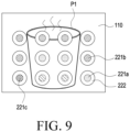
- FIG. 9 is a diagram illustrating an elastic part 110 viewed from a camera unit 130 and a plurality of markers 220 having different temperatures depending on locations according to embodiments of the disclosure.
- the optical tactile sensor module 100 may include an elastic part 110 and a marker 220. All or some of the configurations of the elastic part 110 and the marker 220 in FIGS. 7A to 8 may be the same as the configurations of the elastic part 110 and the marker 220 in FIG. 5 .
- "X” may indicate the longitudinal direction of the optical tactile sensor module 100.
- “Y” may indicate the width direction of the optical tactile sensor module 100.
- “+X” may indicate the right direction of the optical tactile sensor module 100, and “-X” may indicate the left direction of the optical tactile sensor module 100.
- “+Y” may indicate the forward direction of the optical tactile sensor module 100, and “-Y” may indicate the backward direction of the optical tactile sensor module 100.
- the first color of the first marker 221 may include a thermosensitive pigment whose color changes depending on temperature.
- measurable temperature may be divided into a plurality of ranges, and a plurality of colors may be specified according to the ranges.
- Thermosensitive pigments are pigments that change their colors depending on temperature, and the color begins to disappear as the temperature rises and returns back to its original color when the temperature falls again.
- Thermosensitive pigments change colors at intervals of 2 to 10 degrees C between -15 degrees C and 70 degrees C, and there are various grades of pigments, such as pigments that change colors when the temperature rises by 2 degrees C from 20 degrees C, pigments that change colors at 31 degrees C, 43 degrees C, and 65 degrees C, or the like.
- thermosensitive pigment which changes at 20 degrees C, appears blue at 20 degrees C or less, and the color disappears at 22 degrees C.
- the orange thermosensitive pigment which changes at 31 degrees C, appears orange at 31 degrees C, and the color completely disappears at 35 degrees C when heated.
- the red thermosensitive pigment which changes at 43 degrees C, appears red at 43 degrees C, and the color completely disappears at 47 degrees C when heated.
- thermosensitive pigments there are various colors of thermosensitive pigments, and different colors may be obtained through a combination of two types of thermosensitive pigments or a combination of thermosensitive pigments and regular pigments, and different products may be obtained through a combination of three or more thermosensitive pigments with different temperatures, which may meet various requirements of products depending on the development.
- a combination of a 20 degrees C-thermosensitive pigment, a 31 degrees C- thermosensitive pigment, and a 43 degrees C- thermosensitive pigment may be configured such that the color changes at 25 degrees C, changes to another color at 35 degrees C, and then changes to another color when the temperature rises 45 degrees C or above.
- thermosensitive pigments are merely illustrative, and the disclosure is not limited thereto, and it is obvious to persons who are skilled in the art (hereinafter referred to as “those skilled in the art") that various commercially available thermosensitive pigments may be appropriately selected and used.
- thermosensitive pigment is selected in the temperature range of -15 to 70 degrees C, it is obvious to those skilled in the art that thermosensitive pigments may be selected in a temperature range that does not affect other elements of the optical tactile sensor module 100, considering that the first marker 221 of the marker 120 is used in the optical tactile sensor module 100.
- the first marker 221 having the first color may change to the 1a th marker 221a having the 1a th color.
- the first marker 221 having the first color may change to the 1b th marker 221b having the 1b th color.
- the first marker 221 having the first color may change to the 1c th marker 221c having the 1c th color.
- the temperature range in which the color changes is not limited to the above embodiment and may be designed in various ways depending on the intended use.
- the measured temperature may vary depending on the location of the marker 220.
- a specified portion includes an external object (e.g., the external object P1 in FIG. 8 ) having a specific temperature
- the temperature measured in the marker 220 close to the portion may be different from the temperature measured in the marker 220 far from the portion. Therefore, by measuring the temperature depending on the location, it is possible to identify the contact of the external object (e.g., the external object P1 in FIG. 8 ) and the contact area thereof.
- An optical tactile sensor module (e.g., the optical tactile sensor module 100 in FIG. 1 ) may include a housing (e.g., the housing 140 in FIG. 1 ), a circuit board disposed inside the housing, an elastic part (e.g., the elastic part 110 in FIG. 1 ) including a first surface (e.g., the first surface 111 in FIG. 1 ) to come into contact with an object, a plurality of markers (e.g., the plurality of markers 120 in FIG. 1 ) disposed on the first surface of the elastic part, and a camera unit (e.g., the camera unit 130 in FIG.
- a housing e.g., the housing 140 in FIG. 1
- an elastic part e.g., the elastic part 110 in FIG. 1
- a plurality of markers e.g., the plurality of markers 120 in FIG. 1
- a camera unit e.g., the camera unit 130 in FIG.
- the markers may include a first marker (e.g., the first marker 221 in FIG. 6 ) including a first color, and a second marker (e.g., the second marker 222 in FIG. 6 ) including a second color different from the first color.
- a first marker e.g., the first marker 221 in FIG. 6
- a second marker e.g., the second marker 222 in FIG. 6
- the first marker may be a circular marker having a radius with a first length (e.g., the first length r1 in FIG. 6 ).
- the second marker may be formed to surround the edge of the first marker, and the outer perimeter of the second marker may form a circle having a radius with a second length (e.g., the second length r2 in FIG. 6 ) longer than the first length.
- the first marker may include a thermosensitive pigment.
- the first color of the first marker may change to a 1a th color if a temperature within a first range is measured, change to a 1b th color if a temperature within a second range higher than the temperature in the first range is measured, and change to a 1c th color if a temperature within a third range higher than the temperature in the second range is measured.
- the plurality of markers may be arranged at regular intervals.
- the elastic part may include an optically transparent material such as at least one of a silicone resin and an elastomer.
- the elastic part may include an optically translucent material.
- the markers and the object may be displayed on a screen captured by the camera unit.
- the movement of the marker may include at least one of displacement, deformation, or tilt of the marker.
- connection part to be connected to an external electronic device may be further included.
- the external electronic device may be an industrial robot.
- An electronic device may include an optical tactile sensor module and a circuit board electrically connected to the optical tactile sensor module, wherein the optical tactile sensor module may include a housing, an elastic part including a first surface to come into contact with an object, a plurality of markers disposed on the first surface of the elastic part, and a camera unit configured to capture movements of at least some of the markers when the object approaches the first surface of the elastic part, wherein the markers may include a first marker including a first color, and a second marker including a second color different from the first color.
- the first marker may be a circular marker having a radius with a first length.
- the second marker may be formed to surround the edge of the first marker, and the outer perimeter of the second marker may form a circle having a radius with a second length greater than the first radius.
- the first marker may include a thermosensitive pigment.
- the first color of the first marker may change to a 1a th color if a temperature in a first range is measured, change to a 1b th color if a temperature in a second range higher than the temperature in the first range is measured, and change to a 1c th color if a temperature in a third range higher than the temperature in the second range is measured.
- the plurality of markers may be arranged at regular intervals.
- the elastic part may include an optically transparent material such as at least one of a silicone resin and an elastomer.
- the elastic part may include an optically translucent material.
- optical tactile sensor e.g., the optical tactile sensor module 100 in FIG. 1
- optical tactile sensor e.g., the optical tactile sensor module 100 in FIG. 1
- the optical tactile sensor is not limited to the above-described embodiments and drawings, and it will be obvious to those skilled in the art to which the disclosure pertains that various modifications, substitutions, and changes are possible within the scope of the disclosure.
Landscapes
- Engineering & Computer Science (AREA)
- Physics & Mathematics (AREA)
- General Physics & Mathematics (AREA)
- Robotics (AREA)
- Theoretical Computer Science (AREA)
- Mechanical Engineering (AREA)
- Multimedia (AREA)
- Computer Vision & Pattern Recognition (AREA)
- Chemical & Material Sciences (AREA)
- Analytical Chemistry (AREA)
- Force Measurement Appropriate To Specific Purposes (AREA)
Applications Claiming Priority (2)
| Application Number | Priority Date | Filing Date | Title |
|---|---|---|---|
| KR1020220005109A KR20230109303A (ko) | 2022-01-13 | 2022-01-13 | 광학식 촉각 센서 |
| PCT/KR2023/000405 WO2023136576A1 (fr) | 2022-01-13 | 2023-01-10 | Capteur tactile optique |
Publications (2)
| Publication Number | Publication Date |
|---|---|
| EP4459253A1 true EP4459253A1 (fr) | 2024-11-06 |
| EP4459253A4 EP4459253A4 (fr) | 2025-04-09 |
Family
ID=87279502
Family Applications (1)
| Application Number | Title | Priority Date | Filing Date |
|---|---|---|---|
| EP23740420.7A Pending EP4459253A4 (fr) | 2022-01-13 | 2023-01-10 | Capteur tactile optique |
Country Status (4)
| Country | Link |
|---|---|
| US (1) | US20240362801A1 (fr) |
| EP (1) | EP4459253A4 (fr) |
| KR (1) | KR20230109303A (fr) |
| WO (1) | WO2023136576A1 (fr) |
Families Citing this family (2)
| Publication number | Priority date | Publication date | Assignee | Title |
|---|---|---|---|---|
| KR102767057B1 (ko) | 2023-11-23 | 2025-02-14 | 한국생산기술연구원 | 광학식 촉각센서 |
| JP2025150184A (ja) * | 2024-03-27 | 2025-10-09 | 三星電子株式会社 | 保持装置 |
Family Cites Families (13)
| Publication number | Priority date | Publication date | Assignee | Title |
|---|---|---|---|---|
| EP1321753B1 (fr) * | 2000-08-31 | 2008-09-17 | TOUDAI TLO, Ltd. | Detecteur tactile optique |
| JP2003034005A (ja) * | 2001-07-24 | 2003-02-04 | Pilot Ink Co Ltd | 金属光沢調可逆感温多色変色性積層体 |
| JP4106611B2 (ja) * | 2003-01-31 | 2008-06-25 | 学校法人日本大学 | 触覚測定方法および触覚センサ |
| JP4206057B2 (ja) * | 2003-09-16 | 2009-01-07 | 株式会社東京大学Tlo | 光学式触覚センサを用いた力ベクトル再構成法 |
| CA2538008A1 (fr) * | 2003-09-16 | 2005-03-31 | Toudai Tlo, Ltd. | Capteur tactile optique et procede de restitution de la repartition d'un vecteur de force au moyen du capteur |
| JP4621827B2 (ja) * | 2004-03-09 | 2011-01-26 | 財団法人名古屋産業科学研究所 | 光学式触覚センサ、光学式触覚センサを利用したセンシング方法、センシングシステム、物体操作力制御方法、物体操作力制御装置、物体把持力制御装置及びロボットハンド |
| JP2006003137A (ja) * | 2004-06-16 | 2006-01-05 | Toudai Tlo Ltd | 光学式触覚センサ及び該センサにおける情報取得方法 |
| JP2018115923A (ja) * | 2017-01-17 | 2018-07-26 | 株式会社エンプラス | マーカ |
| CN110446912B (zh) * | 2017-03-23 | 2021-07-20 | 松下知识产权经营株式会社 | 触觉传感器以及构成该触觉传感器的触觉传感器单元 |
| CN109015763A (zh) * | 2018-08-30 | 2018-12-18 | 清华大学 | 一种基于感温变色油墨材料的多模态触觉感知装置 |
| EP3693139A1 (fr) * | 2019-02-11 | 2020-08-12 | Université d'Aix-Marseille | Capteur tactile optique |
| JP2021154412A (ja) * | 2020-03-25 | 2021-10-07 | 株式会社Preferred Networks | 触覚センサシステム、把持システム、制御方法及び制御プログラム |
| US11656759B2 (en) * | 2020-06-10 | 2023-05-23 | Samsung Electronics Co., Ltd. | Semitransparent tactile surface sensor and a method of sensing an interaction with an object using the semitransparent tactile surface sensor |
-
2022
- 2022-01-13 KR KR1020220005109A patent/KR20230109303A/ko active Pending
-
2023
- 2023-01-10 WO PCT/KR2023/000405 patent/WO2023136576A1/fr not_active Ceased
- 2023-01-10 EP EP23740420.7A patent/EP4459253A4/fr active Pending
-
2024
- 2024-07-09 US US18/767,431 patent/US20240362801A1/en active Pending
Also Published As
| Publication number | Publication date |
|---|---|
| WO2023136576A1 (fr) | 2023-07-20 |
| KR20230109303A (ko) | 2023-07-20 |
| US20240362801A1 (en) | 2024-10-31 |
| EP4459253A4 (fr) | 2025-04-09 |
Similar Documents
| Publication | Publication Date | Title |
|---|---|---|
| US11488366B2 (en) | Augmented reality lighting effects | |
| Padmanabha et al. | Omnitact: A multi-directional high-resolution touch sensor | |
| EP4459253A1 (fr) | Capteur tactile optique | |
| US10897940B2 (en) | Gloves having measuring, scanning, and displaying capabilities | |
| US11806864B2 (en) | Robot arm assemblies including fingers having deformable sensors | |
| US10249030B2 (en) | Image transformation for indicia reading | |
| KR102716043B1 (ko) | 전자 장치 및 전자 장치의 오브젝트 측정 방법 | |
| CN111758188B (zh) | 包括金属板的连接器和包括该连接器的电子装置 | |
| US10509512B2 (en) | Operation input device and image processing system | |
| JP6016760B2 (ja) | 作業確認システム | |
| JP2005275439A (ja) | Ui設計評価方法及び装置 | |
| KR102616417B1 (ko) | 디스플레이를 구비한 전자 장치 | |
| TWI482050B (zh) | 可攜式電子裝置、容置裝置、容置裝置識別之方法以及其識別系統 | |
| US12041336B2 (en) | Sensor assembly including light control member and electronic device including the same | |
| KR20130122151A (ko) | 인터랙티브 디스플레이 디바이스 및 그 제어 방법 | |
| KR102600509B1 (ko) | 전자 장치 및 그 촬영 관련 정보 안내 방법 | |
| KR20230096431A (ko) | 광학식 촉각 센서 | |
| KR20200138551A (ko) | 캘리브레이션 장치 및 이를 포함하는 캘리브레이션 시스템 | |
| US20250362173A1 (en) | Light altering devices for light sensors | |
| JP2025177596A (ja) | 視触覚センサ | |
| CN120907698A (zh) | 触觉传感器、电子皮肤和智能体 | |
| KR101387403B1 (ko) | 회전 각도를 감지하는 카메라 | |
| TWM492009U (zh) | 可提升精準度的溫度量測裝置 | |
| Hirooka et al. | 3D camera calibration using gray code patterns | |
| EP3136048A1 (fr) | Gants ayant des capacités de mesure, balayage et d'affichage |
Legal Events
| Date | Code | Title | Description |
|---|---|---|---|
| STAA | Information on the status of an ep patent application or granted ep patent |
Free format text: STATUS: THE INTERNATIONAL PUBLICATION HAS BEEN MADE |
|
| PUAI | Public reference made under article 153(3) epc to a published international application that has entered the european phase |
Free format text: ORIGINAL CODE: 0009012 |
|
| STAA | Information on the status of an ep patent application or granted ep patent |
Free format text: STATUS: REQUEST FOR EXAMINATION WAS MADE |
|
| 17P | Request for examination filed |
Effective date: 20240801 |
|
| AK | Designated contracting states |
Kind code of ref document: A1 Designated state(s): AL AT BE BG CH CY CZ DE DK EE ES FI FR GB GR HR HU IE IS IT LI LT LU LV MC ME MK MT NL NO PL PT RO RS SE SI SK SM TR |
|
| REG | Reference to a national code |
Ref country code: DE Ref legal event code: R079 Free format text: PREVIOUS MAIN CLASS: G01L0001240000 Ipc: B25J0009160000 |
|
| A4 | Supplementary search report drawn up and despatched |
Effective date: 20250310 |
|
| RIC1 | Information provided on ipc code assigned before grant |
Ipc: G06T 1/00 20060101ALI20250305BHEP Ipc: G06T 7/246 20170101ALI20250305BHEP Ipc: G01L 5/22 20060101ALI20250305BHEP Ipc: G01L 1/24 20060101ALI20250305BHEP Ipc: B25J 9/16 20060101AFI20250305BHEP |
|
| DAV | Request for validation of the european patent (deleted) | ||
| DAX | Request for extension of the european patent (deleted) |