EP4459382A1 - Dekorationsgegenstand - Google Patents
Dekorationsgegenstand Download PDFInfo
- Publication number
- EP4459382A1 EP4459382A1 EP23171235.7A EP23171235A EP4459382A1 EP 4459382 A1 EP4459382 A1 EP 4459382A1 EP 23171235 A EP23171235 A EP 23171235A EP 4459382 A1 EP4459382 A1 EP 4459382A1
- Authority
- EP
- European Patent Office
- Prior art keywords
- plate
- decorative object
- pockets
- plates
- Prior art date
- Legal status (The legal status is an assumption and is not a legal conclusion. Google has not performed a legal analysis and makes no representation as to the accuracy of the status listed.)
- Pending
Links
Images


Classifications
-
- G—PHYSICS
- G04—HOROLOGY
- G04B—MECHANICALLY-DRIVEN CLOCKS OR WATCHES; MECHANICAL PARTS OF CLOCKS OR WATCHES IN GENERAL; TIME PIECES USING THE POSITION OF THE SUN, MOON OR STARS
- G04B45/00—Time pieces of which the indicating means or cases provoke special effects, e.g. aesthetic effects
- G04B45/0015—Light-, colour-, line- or spot-effects caused by or on stationary parts
-
- A—HUMAN NECESSITIES
- A44—HABERDASHERY; JEWELLERY
- A44C—PERSONAL ADORNMENTS, e.g. JEWELLERY; COINS
- A44C17/00—Gems or the like
- A44C17/02—Settings for holding gems or the like, e.g. for ornaments or decorations
- A44C17/0283—Settings for holding gems or the like, e.g. for ornaments or decorations moving freely inside a setting
- A44C17/0291—Settings for holding gems or the like, e.g. for ornaments or decorations moving freely inside a setting in the same plane
-
- A—HUMAN NECESSITIES
- A44—HABERDASHERY; JEWELLERY
- A44C—PERSONAL ADORNMENTS, e.g. JEWELLERY; COINS
- A44C25/00—Miscellaneous fancy ware for personal wear, e.g. pendants, crosses, crucifixes, charms
-
- G—PHYSICS
- G04—HOROLOGY
- G04B—MECHANICALLY-DRIVEN CLOCKS OR WATCHES; MECHANICAL PARTS OF CLOCKS OR WATCHES IN GENERAL; TIME PIECES USING THE POSITION OF THE SUN, MOON OR STARS
- G04B45/00—Time pieces of which the indicating means or cases provoke special effects, e.g. aesthetic effects
- G04B45/0007—Light-, colour-, line-, or spot-effects caused by parts or pictures moved by the clockwork
-
- G—PHYSICS
- G04—HOROLOGY
- G04B—MECHANICALLY-DRIVEN CLOCKS OR WATCHES; MECHANICAL PARTS OF CLOCKS OR WATCHES IN GENERAL; TIME PIECES USING THE POSITION OF THE SUN, MOON OR STARS
- G04B47/00—Time-pieces combined with other articles which do not interfere with the running or the time-keeping of the time-piece
- G04B47/04—Time-pieces combined with other articles which do not interfere with the running or the time-keeping of the time-piece with attached ornaments or amusement apparatus
- G04B47/044—Movable decorations and parts thereof
Definitions
- the present invention relates to the field of watchmaking and jewelry. It concerns, more particularly, a decorative object such as a watch glass, a watch dial or a piece of jewelry.
- the document EP3414108 describes a decorative object, in particular a watch glass, consisting of two glass panes secured to each other.
- a hollow pattern is formed in the lower glass pane opposite the upper glass pane and is filled with a liquid and a quantity of balls suspended in the liquid.
- the balls can move under the effect of gravity in the hollow, to follow its shape and show its geometry.
- the aim of the invention is to provide decorative objects with a variable, unexpected, particular and attractive appearance.
- At least some of said pockets have two interior corners, rounded or pointed, providing at least two stable positions for a corresponding movable element located in said corresponding pocket, said stable positions being defined for at least two orientations of said decorative object when the latter is oriented with respect to the gravity vector such that said corresponding movable element is located in one of said corners.
- the visual appearance of the decorative object varies accordingly depending on its orientation relative to the gravity vector, the positions of at least some of the moving elements being constant for certain orientations.
- At least some of said stable positions are substantially the same for at least some of said pockets, such that the corresponding movable elements adopt a stable position simultaneously, depending on the orientation of the object relative to the gravity vector.
- said corners may have similar orientations in the plane of the object for the pockets concerned.
- the orientations may alternatively be different.
- said moving elements are balls.
- said gap is filled with a liquid, preferably of a dark color or having a refractive index which is substantially the same as at least said second plate.
- the arrangement of the movable elements in said pocket can be varied, thus modifying the appearance of said decorative object.
- said second plate comprises a hollow which is located opposite said second plate and defines a face of said pocket.
- This hollow will be filled with mobile elements when said actuator system is in its second state, and their distribution can be predetermined by the shape chosen for said hollow.
- said mechanical actuator comprises a plurality of pivotally mounted arms arranged to move between predetermined positions to define said first state and said second state.
- These arms may, for example, define a clamp or an iris mechanism, may have any number of stable positions, the transition between states may be discrete (i.e. by jumps) or continuous.
- said actuator system may comprise a hydraulic membrane or a piston.
- said gap is filled with a dark-colored liquid, and/or having substantially the same refractive index as at least said second plate, as well as, where appropriate, said levers if they are made at least partially of transparent material.
- the movable elements can be hidden when the actuator system is in its first state and the second plate is oriented upwards, i.e. opposite the gravity vector.
- Each movable element comprises a first plate superimposed on a second plate and connected to the latter via a plurality (typically at least three) of elongated connecting elements, which may be substantially rigid or flexible.
- the appearance of the decorative object can be varied via the actuators.
- each movable element is linked to a corresponding cooperation element, linked to an adjacent movable element by interlacing adjacent connecting elements comprised by said adjacent movable elements, but the use of links or other additional links is also possible.
- each of said elongated connecting elements is of helical shape.
- each moving element is a single piece.
- Figures 1 ad And 2 ac illustrate a first embodiment of a decorative object 1 according to the invention.
- the decorative object is formed of a first plate 3 secured to a second plate 5, which is at least partially transparent and is intended to be located opposite a user, a plurality of pockets 7 being provided between the two plates 3, 5.
- These pockets 7 can be formed in several ways.
- the pockets 7 are formed by hollows 7b in the face of the second plate 5 which are located opposite the first plate 3.
- each plate 3, 5 is hollowed out on its face which is opposite the other so that the hollows 7b in each plate 3, 5 form the pockets 7.
- it is the first plate 3 which is hollowed out on its face which is opposite the second plate 5.
- none of the plates 3, 5 are hollowed out, the pockets 7 being defined by through openings provided in an intermediate plate 9 located between the plates 3, 5.
- each pocket 7 houses a mobile element 11, here a ball 11, but it is possible that only some of the latter house one and/or house several.
- Each of the plates 3, 5 may, for example, be made of borosilicate glass, crystalline glass, fused silica, crown glass, flint glass, quartz, transparent ceramic, sapphire, polymethyl methacrylate, polycarbonate, polyurethane.
- the first plate 3, which is intended to be located further away from the observer, may also be made of opaque material, such as a metal, polymer or the like.
- the pockets 7 may be filled with a fluid, for example having a refractive index that is similar to that of one or the other (or both) of the plates 3, 5.
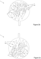
- FIGS. 2a-c illustrate such a decorative object 1 in plan views, held vertically, that is to say with the plane of the object 1 substantially parallel to the gravity vector, which is directed towards the bottom of the page, in three different angular orientations around an axis perpendicular to the plane of the decorative object 1.
- stable position it is understood that the ball remains substantially immobile during a rotation of at least ⁇ 10°, preferably at least ⁇ 20°, about an axis perpendicular to the plane of the object 1 when the latter is pivoted.
- polygonal shapes, shapes having lobes, corners or the like, shapes which define sharp or rounded interior corners (for example those indicated with the reference signs 7a1, 7a2 and 7a3) in which the balls can be positioned under the effect of gravity.
- the other pockets 7 can take any shape.
- the decorative object 1 may be part of a piece of jewelry or jewelry, or a timepiece.
- the decorative object 1 may act as a glass or a dial, and may be fixed relative to the caseband or be pivotally mounted relative to the latter under the effect of gravity, a drive source integrated into the piece, an operating member (crown, rotating bezel, rotating back), an oscillating weight or the like.
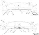
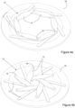
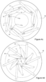
- FIGS. 3a, 3b , 4a, 4b , 4c and 4d illustrate a second embodiment of a decorative object 1 according to the invention. Characteristics which are equivalent to those of the Figures 1a to 2c have the same reference signs to facilitate reading.
- This embodiment comprises a first plate 3 and a second plate 5, which is at least partially transparent and is intended to be located opposite a user. These two plates 3, 5 are arranged parallel to each other, so as to define between them a gap comprising a pocket 7 of variable volume.
- the second plate 5 has a hollow 7b on its face which is opposite the first plate 3, which is centered on the plates 3, 5, but this is not obligatory.
- the volume of the pocket 7 is varied by means of an actuator system 13, which takes the form of an “iris” or “diaphragm” type mechanism located in the gap between the two plates 3, 5.
- This actuator system comprises a plurality of levers 15 pivotally mounted on the plate 3 by means of studs 16, which take place in holes provided for this purpose, according to an arrangement which is rotationally symmetrical, the levers 15 being adapted to occupy substantially the entire thickness between the plates 3, 5, and thus to vary the volume of the pocket 7 when they evolve between a first state, open (as illustrated in the Figures 3a , 4a And 4c ) and a second closed state (as illustrated in the Figures 3b , 4b And 4d ).
- This evolution is controlled by a relative rotation between the plate 3 and an outer ring 18, on which first ends of support rockers 17 are pivoted, the second ends of the latter being pivotally connected near the distal ends of the levers 15 by means of connecting pins 17a.
- This relative rotation can, for example, be obtained by means of a rotating bezel, a rotating back, a crown, a pusher, a target or any other suitable operating member which is kinematically connected to the plate 3 or to the outer ring 18, the other being fixed.
- the variable volume pocket 7 houses a plurality of movable elements 11, again balls 11, the quantity being chosen such that, in the first state of the actuator system 13, the balls 11 do not fill the pocket 7, while in the second state, the pocket 7 is filled and the balls 11 are forced into the recess 7b, the configuration of the latter and of the levers 15 being chosen such that the balls 11 cannot escape from the pocket 7, and the shape of the recess 7b being chosen to obtain the desired distribution of movable elements 11.
- the pocket 7, as well as the entire gap between the two plates 3, 5, may be filled with liquid, in the same way as mentioned for the pockets of the first embodiment.
- This liquid may also, for example, be dark in color in order to hide the balls 11 in the first state of the actuator system 13, such that they are only visible when the latter is in its second state, in which the balls 11 are forced against the inner surface of the recess 7b.
- the liquid may have a refractive index that is substantially the same as that of the plate 5 and/or the arms 15 and/or flip-flops 17, these elements thus being at least partially constructed of transparent material.
- the decorative object 1 may be part of a piece of jewelry or jewelry, or a timepiece.
- the decorative object 1 may act as a dial, and may be fixed relative to the caseband, an operating member (crown, rotating bezel, rotating back) being provided to control the actuator system 13.
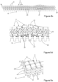
- FIGS. 5a to 5e illustrate a third embodiment of a part of a decorative element 1 according to the invention.
- the movable elements 11 each comprise a first plate 12 superimposed on a second plate 23, four connecting elements 19 connecting them to each other.
- the connecting elements 19 each have a helical shape, but this is not obligatory, and rectilinear, bent or similar shapes are also possible.
- the movable elements 11 are arranged so as to form a matrix or a network and are connected to each other in an articulated manner, so as to allow relative movement with respect to each other under the effect of an actuator system 13 comprising a plurality of actuators 21 associated with at least some of the movable elements 11.
- the articulated connection between the movable elements 11 can be carried out in any suitable manner, for example by means of flexible blades (flexures), additional links connecting one connecting element 19 to another movable element 11 of the adjacent connecting element 19 or the like.
- each second plate 23 is arranged to cooperate with a corresponding actuator 21, here an actuation cam 21 a plurality of which are mounted on axes 25 which can be rotated by an electric motor, a watch mechanism or manually by manipulating an operating member such as a crown, a rotating bezel or back, a target or the like.
- actuation cam 21 a plurality of which are mounted on axes 25 which can be rotated by an electric motor, a watch mechanism or manually by manipulating an operating member such as a crown, a rotating bezel or back, a target or the like.
- a restoring force may be provided in an ad hoc manner, such as by gravity, by elastic elements or by making the connections between the movable elements 11 elastic.
- the connecting elements 19 each have a helical shape, and are distributed equally around each first plate 12 and each second plate 23 such that a connecting element 19 of a movable element 11 is intertwined with a connecting element 19 of an adjacent movable element 11 (if present).
- the connecting elements 19 are thus “linked arms”, and this cooperation between connecting elements 19 ensures the articulation between the movable elements 11 to form the matrix and, in the case where they are elastic, provide a restoring force serving to hold the second plates 23 against their respective cams.
- actuators 21 are also possible, such as for example a plurality of independent pistons, one or more objects (plates, balls, sculptures, etc.) arranged to be moved according to a direction parallel or perpendicular to the plane of the die to move the movable elements, etc.
- the movable elements 11 are advantageously monobloc, that is to say each made of a single tenon, without discontinuity of material, and can be manufactured by additive manufacturing (3D printing). Depending on the material chosen as well as the dimensions of the connecting elements 19, the latter can be substantially rigid or flexible.
- the matrix of movable elements 11 is square in the embodiment of the figures. However, it is also possible to arrange them in a triangular or hexagonal matrix, the number of flexible elements 19 being adapted accordingly (i.e. three in the case of a triangular matrix or six in the case of a hexagonal matrix). Furthermore, the matrix may have interstices instead of being complete, and the first plates 12 may be arranged to have a relief topography, whether positive or negative, bump or hollow.
- the assembly of plates 11, flexures 19 and cooperating elements is connected to a frame (not shown) in any suitable manner and protected by glass (not shown) so that this assembly acts as a dial of a watch or forms part of a piece of jewelry.
Landscapes
- Physics & Mathematics (AREA)
- General Physics & Mathematics (AREA)
- Adornments (AREA)
Priority Applications (1)
| Application Number | Priority Date | Filing Date | Title |
|---|---|---|---|
| EP23171235.7A EP4459382A1 (de) | 2023-05-03 | 2023-05-03 | Dekorationsgegenstand |
Applications Claiming Priority (1)
| Application Number | Priority Date | Filing Date | Title |
|---|---|---|---|
| EP23171235.7A EP4459382A1 (de) | 2023-05-03 | 2023-05-03 | Dekorationsgegenstand |
Publications (1)
| Publication Number | Publication Date |
|---|---|
| EP4459382A1 true EP4459382A1 (de) | 2024-11-06 |
Family
ID=86328914
Family Applications (1)
| Application Number | Title | Priority Date | Filing Date |
|---|---|---|---|
| EP23171235.7A Pending EP4459382A1 (de) | 2023-05-03 | 2023-05-03 | Dekorationsgegenstand |
Country Status (1)
| Country | Link |
|---|---|
| EP (1) | EP4459382A1 (de) |
Citations (16)
| Publication number | Priority date | Publication date | Assignee | Title |
|---|---|---|---|---|
| US5305292A (en) * | 1992-12-18 | 1994-04-19 | Daniel Reynoso | Fluid filled watch apparatus |
| EP0869409A2 (de) * | 1997-04-02 | 1998-10-07 | Vincenzo Testa | Analogarmbanduhr mit übereinander angeordneten Zifferblättern |
| US20030115903A1 (en) * | 2001-04-17 | 2003-06-26 | Giuseppe Scharf | Segmented jewelry item |
| FR2862353A1 (fr) * | 2003-11-17 | 2005-05-20 | Commissariat Energie Atomique | Actionneur multi-stable a base d'alliage a memoire de forme, et interface tactile le mettant en oeuvre |
| WO2015150910A2 (en) * | 2014-04-03 | 2015-10-08 | Preciflex Sa | Systems and methods for absorption/expansion/contraction/movement of a liquid in a transparent cavity |
| CH712113A1 (fr) * | 2016-02-12 | 2017-08-15 | Cartier Int Ag | Objet décoratif, en particulier glace de montre, à effet optique. |
| CH711228B1 (fr) * | 2015-06-19 | 2019-01-31 | Vaucher Mft Fleurier S A | Dispositif d'affichage pour pièce d'horlogerie. |
| US20190216185A1 (en) * | 2016-09-20 | 2019-07-18 | Preciflex Sa | Dynamic fluidic jewelry |
| WO2020070667A1 (en) | 2018-10-02 | 2020-04-09 | Preciflex Sa | Device comprising decorative objects having restrained freedom to move and suspended in fluid |
| EP3435362B1 (de) * | 2017-07-24 | 2020-09-09 | CSEM Centre Suisse D'electronique Et De Microtechnique SA | Anzeigesystem, das ein anzeigemodul über mobile elemente um flexible verbindungen umfasst, und uhr, die ein solches anzeigesystem umfasst |
| JP6863783B2 (ja) * | 2017-03-16 | 2021-04-21 | セイコーインスツル株式会社 | 時計 |
| CN213045706U (zh) * | 2020-08-21 | 2021-04-27 | 广州二元科技有限公司 | 一种香水浓度可以调节的香水耳环 |
| US10996632B2 (en) * | 2015-12-09 | 2021-05-04 | The Swatch Group Research And Development Ltd | Variable colour exterior element |
| CH717628A1 (fr) * | 2020-07-14 | 2022-01-14 | Chopard Tech Sa | Article de joaillerie. |
| WO2022089793A1 (fr) * | 2020-11-02 | 2022-05-05 | Cartier International Ag | Boite de montre deformable |
| US20220248816A1 (en) * | 2019-06-05 | 2022-08-11 | Preciflex Sa | Thermal compensation system for fluidic decoration capsule |
-
2023
- 2023-05-03 EP EP23171235.7A patent/EP4459382A1/de active Pending
Patent Citations (18)
| Publication number | Priority date | Publication date | Assignee | Title |
|---|---|---|---|---|
| US5305292A (en) * | 1992-12-18 | 1994-04-19 | Daniel Reynoso | Fluid filled watch apparatus |
| EP0869409A2 (de) * | 1997-04-02 | 1998-10-07 | Vincenzo Testa | Analogarmbanduhr mit übereinander angeordneten Zifferblättern |
| US20030115903A1 (en) * | 2001-04-17 | 2003-06-26 | Giuseppe Scharf | Segmented jewelry item |
| FR2862353A1 (fr) * | 2003-11-17 | 2005-05-20 | Commissariat Energie Atomique | Actionneur multi-stable a base d'alliage a memoire de forme, et interface tactile le mettant en oeuvre |
| WO2015150910A2 (en) * | 2014-04-03 | 2015-10-08 | Preciflex Sa | Systems and methods for absorption/expansion/contraction/movement of a liquid in a transparent cavity |
| CH711228B1 (fr) * | 2015-06-19 | 2019-01-31 | Vaucher Mft Fleurier S A | Dispositif d'affichage pour pièce d'horlogerie. |
| US10996632B2 (en) * | 2015-12-09 | 2021-05-04 | The Swatch Group Research And Development Ltd | Variable colour exterior element |
| CH712113A1 (fr) * | 2016-02-12 | 2017-08-15 | Cartier Int Ag | Objet décoratif, en particulier glace de montre, à effet optique. |
| EP3414108A1 (de) | 2016-02-12 | 2018-12-19 | Cartier International AG | Dekoratives objekt, insbesondere ein uhrenglas mit optischem effekt |
| US20190216185A1 (en) * | 2016-09-20 | 2019-07-18 | Preciflex Sa | Dynamic fluidic jewelry |
| JP6863783B2 (ja) * | 2017-03-16 | 2021-04-21 | セイコーインスツル株式会社 | 時計 |
| EP3435362B1 (de) * | 2017-07-24 | 2020-09-09 | CSEM Centre Suisse D'electronique Et De Microtechnique SA | Anzeigesystem, das ein anzeigemodul über mobile elemente um flexible verbindungen umfasst, und uhr, die ein solches anzeigesystem umfasst |
| WO2020070667A1 (en) | 2018-10-02 | 2020-04-09 | Preciflex Sa | Device comprising decorative objects having restrained freedom to move and suspended in fluid |
| US20210386165A1 (en) * | 2018-10-02 | 2021-12-16 | Preciflex Sa | Device comprising decorative objects having restrained freedom to move and suspended in fluid |
| US20220248816A1 (en) * | 2019-06-05 | 2022-08-11 | Preciflex Sa | Thermal compensation system for fluidic decoration capsule |
| CH717628A1 (fr) * | 2020-07-14 | 2022-01-14 | Chopard Tech Sa | Article de joaillerie. |
| CN213045706U (zh) * | 2020-08-21 | 2021-04-27 | 广州二元科技有限公司 | 一种香水浓度可以调节的香水耳环 |
| WO2022089793A1 (fr) * | 2020-11-02 | 2022-05-05 | Cartier International Ag | Boite de montre deformable |
Similar Documents
| Publication | Publication Date | Title |
|---|---|---|
| EP2259157B1 (de) | Uhrwerk für armbanduhr | |
| EP3114534B1 (de) | Armbanduhr mit dekorelement | |
| EP3414108B1 (de) | Dekoratives objekt, insbesondere ein uhrenglas mit optischem effekt | |
| EP2593839B1 (de) | Uhr | |
| EP1666992A1 (de) | Uhr mit einer leuchtenden Dekoration | |
| EP2802940A1 (de) | Wickelmasse | |
| EP4182759B1 (de) | Schmuckstück | |
| FR2492998A1 (fr) | Montre a remontage automatique | |
| EP4459382A1 (de) | Dekorationsgegenstand | |
| EP3671363B1 (de) | Uhrwerk und uhr, die ein solches uhrwerk umfasst | |
| EP1840678B1 (de) | Umkehrbare Uhr | |
| WO2021037967A1 (fr) | Mecanisme d'animation d'un objet pour piece de joaillerie ou de bijouterie | |
| CH716453B1 (fr) | Dispositif comprenant des objets décoratifs ayant une liberté de déplacement limitée, suspendus dans un fluide. | |
| EP4012508B1 (de) | Anzeigevorrichtung einer uhr auf mehreren ebenen | |
| CH706350B1 (fr) | Mouvement horloger comprenant un mécanisme de remontage automatique. | |
| EP3940462B1 (de) | Dekorationsobjekt | |
| HK40115816A (en) | Decorative object | |
| EP4202573B1 (de) | Mechanismus zur animation eines objekts für uhr | |
| CH714643A1 (fr) | Composant horloger intégrant au moins un élément d'ornement. | |
| EP3346343B1 (de) | Ausstattungselement für uhr | |
| CH718929B1 (fr) | Mécanisme horloger à effet optique décoratif. | |
| EP0509222A1 (de) | Gliederarmband, insbesonders für Uhren | |
| CH718141A2 (fr) | Dispositif d'affichage d'horlogerie sur plusieurs niveaux. | |
| CH715518A2 (fr) | Méthode de fabrication d'un mécanisme fonctionnel d'horlogerie notamment d'un poussoir ajouré. | |
| WO2017182940A1 (fr) | Article décoratif comportant un élément support |
Legal Events
| Date | Code | Title | Description |
|---|---|---|---|
| PUAI | Public reference made under article 153(3) epc to a published international application that has entered the european phase |
Free format text: ORIGINAL CODE: 0009012 |
|
| STAA | Information on the status of an ep patent application or granted ep patent |
Free format text: STATUS: THE APPLICATION HAS BEEN PUBLISHED |
|
| AK | Designated contracting states |
Kind code of ref document: A1 Designated state(s): AL AT BE BG CH CY CZ DE DK EE ES FI FR GB GR HR HU IE IS IT LI LT LU LV MC ME MK MT NL NO PL PT RO RS SE SI SK SM TR |
|
| RAP1 | Party data changed (applicant data changed or rights of an application transferred) |
Owner name: RICHEMONT INTERNATIONAL SA |
|
| STAA | Information on the status of an ep patent application or granted ep patent |
Free format text: STATUS: REQUEST FOR EXAMINATION WAS MADE |
|
| 17P | Request for examination filed |
Effective date: 20250225 |
|
| REG | Reference to a national code |
Ref country code: HK Ref legal event code: DE Ref document number: 40115816 Country of ref document: HK |
|
| GRAP | Despatch of communication of intention to grant a patent |
Free format text: ORIGINAL CODE: EPIDOSNIGR1 |
|
| STAA | Information on the status of an ep patent application or granted ep patent |
Free format text: STATUS: GRANT OF PATENT IS INTENDED |