EP4459384A1 - Akustische messung der durchdringung einer palette durch die zähne eines hemmungsrad - Google Patents
Akustische messung der durchdringung einer palette durch die zähne eines hemmungsrad Download PDFInfo
- Publication number
- EP4459384A1 EP4459384A1 EP23170978.3A EP23170978A EP4459384A1 EP 4459384 A1 EP4459384 A1 EP 4459384A1 EP 23170978 A EP23170978 A EP 23170978A EP 4459384 A1 EP4459384 A1 EP 4459384A1
- Authority
- EP
- European Patent Office
- Prior art keywords
- pallet
- tooth
- penetration
- teeth
- anchor
- Prior art date
- Legal status (The legal status is an assumption and is not a legal conclusion. Google has not performed a legal analysis and makes no representation as to the accuracy of the status listed.)
- Pending
Links
Images

Classifications
-
- G—PHYSICS
- G04—HOROLOGY
- G04D—APPARATUS OR TOOLS SPECIALLY DESIGNED FOR MAKING OR MAINTAINING CLOCKS OR WATCHES
- G04D7/00—Measuring, counting, calibrating, testing or regulating apparatus
- G04D7/002—Electrical measuring and testing apparatus
-
- G—PHYSICS
- G04—HOROLOGY
- G04D—APPARATUS OR TOOLS SPECIALLY DESIGNED FOR MAKING OR MAINTAINING CLOCKS OR WATCHES
- G04D7/00—Measuring, counting, calibrating, testing or regulating apparatus
- G04D7/06—Measuring, counting, calibrating, testing or regulating apparatus for escapements
-
- G—PHYSICS
- G04—HOROLOGY
- G04D—APPARATUS OR TOOLS SPECIALLY DESIGNED FOR MAKING OR MAINTAINING CLOCKS OR WATCHES
- G04D7/00—Measuring, counting, calibrating, testing or regulating apparatus
- G04D7/12—Timing devices for clocks or watches for comparing the rate of the oscillating member with a standard
- G04D7/1257—Timing devices for clocks or watches for comparing the rate of the oscillating member with a standard wherein further adjustment devices are present
- G04D7/1271—Timing devices for clocks or watches for comparing the rate of the oscillating member with a standard wherein further adjustment devices are present for the control mechanism only (from outside the clockwork)
Definitions
- the present invention relates generally to the field of watchmaking, more particularly to the field of fault detection on components and assemblies.
- the aim of the present invention is to propose a new way of detecting a fault in the adjustment of watch components and of proposing an adjustment of these in order to make them compliant.
- the document CH691992 discloses a measurement of balance amplitude by optical measurement, a measurement of balance travel time by analysis of emitted sounds, and a determination of a travel angle based on the amplitude and travel time.
- an existing method is based on direct optical measurements by image processing (e.g. Divalog or LecControl). These measurements require a movement without a balance and optical access to the tooth contact on the pallet.
- image processing e.g. Divalog or LecControl.
- the accuracy and repeatability of optical measurements is a point of attention. On a repetition of measurements on several movements, the measurement precision is not satisfactory compared to the required objective, even in the case where the measurements are consistent in relative terms (e.g. relative order and delta).
- the optical measurement e.g. Divalog
- the play adjustments and the dynamic components modify the real penetrations by an unknown and unmeasurable value.
- the prior art does not allow to diagnose, in a reliable manner and in operation, a pallet penetration distance on escape wheel teeth in operation nor to propose an adjustment in order to arrive at a desired position.
- multimode piezoacoustic detection or, more advantageously, acoustic and ultrasonic stethoscopic detection make it possible to achieve sufficient fidelity in terms of accuracy and precision for such a diagnosis, as well as its ease of implementation.
- Penetration means a distance of engagement of the pallet with the tooth of the wheel, in particular on a resting plane of the pallet. Duration means a space of time, a measurable period during which an event, a phenomenon, an action takes place.
- the invention makes it possible to propose a diagnosis making it possible to deduce a pallet penetration distance on at least one escape wheel tooth, and thus deduce whether it is appropriate to adjust the components and/or the assembly.
- this makes it possible to avoid unnecessary adjustment or to allow more efficient or more precise adjustment for the watchmaker, i.e. to limit the effort (physical and mental) for the watchmaker, via a graphical interface or another type of interface, such as a sound interface.
- This also allows better management of penetrations. It is thus possible to inform the person skilled in the art about the possible correction to be made, and preferably in real time, i.e. this improves understanding and knowledge of the escapement.
- the prediction machine thus makes it possible to predict whether the penetration distance is correct, and thus to propose a correction or an adjustment instruction.
- the penetration is too weak, there is a risk of rebeating, a risk of poor timing, particularly if the rest phase is not not established correctly (case of shock), or even to the extreme in the case of zero penetration, the system may not work.
- the at least two sounds correspond to the sounds of the release and the impulse.
- the penetration adjustment is selected from a movement of the at least one pallet in a pallet housing of the anchor, a change of the at least one pallet, a change of the escape wheel or a displacement of the center distance between the anchor and the escape wheel.
- the center distance can be defined as a distance between the anchor stem and the axis of rotation of the escape wheel.
- the two sound signals correspond to the sounds of the release and the impulse of the pallet with the tooth.
- the overall penetration adjustment is selected from a movement of the at least one pallet in a pallet housing of the anchor (also called a pallet system), a change of the at least one pallet, a change of the escape wheel or a movement of the center distance between the anchor and the escape wheel.
- Moving the pallet in its pallet housing means pushing the pallet in or out of its housing. It is also possible to provide for a stripping of the pallets, or in extreme cases (or if necessary or more efficient) a change of pallet(s) or wheel.
- a sound (or several sounds) is emitted, which may correspond at least in part to the so-called "TIC” sounds or to the so-called “TAC” sounds, in a conventional manner. It is thus possible to provide for detecting the sounds at the TIC and the TAC, to take into consideration the characteristics at the TIC and the TAC for the same tooth or for all the teeth, so as to make the deduction more reliable, and in particular thanks to a more developed or robust statistical base. It is also possible to repeat the operations on the input and/or output pallet, at the TIC and the TAC, in order to reinforce the deduction and the quality of the process.
- TIC the sound linked to the contact between a tooth of the escape wheel with the rest plane of a first pallet
- TAC the sound linked to the contact between a tooth of the escape wheel with the rest plane of a second pallet
- the sounds emitted during operation are synchronous.
- Synchronous is an event that occurs at the same time as another or at regular intervals relative to another.
- the piezo-acoustic sensor has in particular a good signal-to-noise ratio over a wide frequency band. It is also possible to provide with this piezo-acoustic sensor a multi-mode operation in order to obtain a high signal-to-noise ratio over a wide frequency range via the natural vibration modes. This has the advantage of being able to go to high frequency, of improving the speed of rise of the sound signal and of obtaining better temporal precision. A measurement via direct contact (solid-borne transmission, for example by a crown) is possible. It is also possible to cut the low frequencies in order to isolate ambient noise.
- MEMS microelectromechanical system
- the plurality of sensors may include four sensors, for example.
- the watch it is possible to install the watch on a structure comprising the sensor with one (or more) acoustic access(es), preferably a felt, a coupling microcavity and one (or more) acoustic access(es) in order to allow the sensor to have greater sensitivity to the sounds of movement.
- a structure comprising the sensor with one (or more) acoustic access(es), preferably a felt, a coupling microcavity and one (or more) acoustic access(es) in order to allow the sensor to have greater sensitivity to the sounds of movement.
- the various sensors mentioned above allow for finer, more faithful listening, and therefore with greater recognition capacity by obtaining a greater quantity of information, by extending the band towards high frequencies which contain useful acoustic energy, by obtaining information less disturbed by the acoustic (and vibrational) environment, by the rapid dissipation of short wavelengths in air and in solids, by obtaining information less disturbed by the connection and electrical environment, by digitizing signals as close as possible to the transduction source, by obtaining very low self-noise by multiplying paired transducers, by the possibility of implementing coherent reconstruction techniques, time shifting, convolution, filtering and focusing, i.e. more precisely all the signal processing methods and acoustic antenna algorithms by microphone arrays and applicable in the near field. Furthermore, by using miniature transducers of known sensitivity and factory matched in amplitude and phase, and for their entire lifetime, the technology does not require initial or periodic calibration.
- the prediction machine comprises a processor and/or a computer.
- the prediction machine further comprises prediction software, such as artificial intelligence.
- the prediction machine comprises one or more neural networks, such as one or more convolutional neural networks.
- the prediction machine can determine the penetration distance and categorize the exhaust as compliant or non-compliant, based on the time elapsed between the two exhaust sound signals.
- the prediction machine must solve the problem of determining the penetration distance and categorizing the exhaust as compliant or non-compliant.
- the prediction machine then receives the elapsed time, uses the model, and determines the penetration distance.
- This learning phase allows to build calibrated reference data for later comparison during a prediction/production phase with defect detection.
- learning allows to obtain test data from reference parts or tested/simulated in parallel to build the model.
- the reference parts can be confirmed by a watchmaker.
- the prediction machine uses a predictive model that can be built from repeated and trained operation.
- a prediction model should be established that can receive as input the elapsed times and output a judgement or determination of a conforming or non-conforming exhaust and a setting instruction. Provision may be made, during the training phase, to provide data relating to the actual sound signals tested, including conforming and non-conforming exhausts.
- the model may include a correlation phase in which the elapsed time is related to the conclusion of conforming or non-conforming exhaust.
- the usage instruction or the adjustment instruction is displayed on a connected device, such as a connected magnifying glass.
- the model is predetermined by construction of the escape wheel and the anchor.
- the model is adapted after operating a plurality of wheels, so as to modify parameters or coefficients of the constructed model.
- the learning process is carried out by machine learning.
- the learning method includes the use of neural networks.
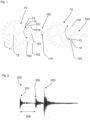
- FIG. 1 represents an escape wheel 10 cooperating with an anchor 100 in a conventional manner.
- the escape wheel 10 tends to want to turn because it is engaged with a barrel of the watch movement (not shown) and the anchor 100 prevents it from turning, or lets it turn at a certain frequency, and transmits energy to an oscillator of the watch movement (not shown) to maintain it.
- the anchor 100 comprises a fork 110 in a conventional manner, in order to allow cooperation with a balance shaft.
- the anchor carries two pallets 101, 102, preferably made of ruby: these are the entry pallet 101 and the exit pallet 102.
- the pallet 101 is housed in an entry pallet housing 101a of the anchor 100 and the pallet 102 is housed in an exit pallet housing 102a of the anchor 100.
- the anchor 100 is rotatable about an axis of rotation of an anchor rod 103 of the anchor 100.
- the escape wheel 10 comprises a plurality of teeth 11 and is rotatable about an axis of rotation of a wheel shaft 12.
- a contact 15 is present when the contacting tooth 13, among the teeth 11 of the escapement wheel 10, comes into contact with one of the pallets 101, 102.
- the escape wheel has twenty teeth 11, including one tooth in contact 13 with the input pallet 101 or the output palette 102, depending on whether we consider the figure 1 left or right.
- Contact 15 can be, for example, an area or a surface.
- TIC can be defined as the sound linked to the contact between a tooth of the escape wheel with the resting plane of a first pallet
- TAC as the sound linked to the contact between a tooth of the escape wheel with the resting plane of a second pallet
- TIC and TAC are a first and a second sound characteristic of the contact between the resting plane of a first and respectively of a second pallet.
- the "TIC” can be considered as the input sound (i.e. of the input pallet on the tooth) and the "TAC” as the output sound of the anchor (i.e. of the output pallet on the tooth) for said tooth of the escapement wheel.
- FIG. 2 represents an acoustic detection of an operation of the escapement, that is to say of the escapement wheel 10 for a given tooth 11, 13 with the anchor 100.
- a detected sound signal 200 comprises a first sound 201, a second sound 202 and a possible third sound 203.
- the third sound 203 is advantageously used to ensure the presence and consistency of the first sound 201 and the second sound 202. in other words, the shape and amplitude of the third sound 203 makes it possible to confirm that the first sound 201 and the second sound 202 are indeed the sounds that one hopes to detect. It is further possible to carry out this confirmation by analyzing an envelope of the sounds 201, 202 or by considering their amplitude or any other parameter, such as a distance from another sound (for example parasitic) not shown. Furthermore, it is possible to use the third sound for measuring the amplitude of the balance wheel.
- the first sound 201 occurs during the first shock, when the roller pin touches the entrance of the pallet fork.
- the second sound 202 occurs when a tooth of the escape wheel falls on the impulse plane of the pallet and the pallet fork catches up with the roller pin.
- the third sound 203 is generally the loudest, and occurs when a tooth of the escape wheel falls onto the pallet resting plane (fall) and the pallet stick presses against the limiting pin (lost path).
- the elapsed time 204 between the first two sounds 201, 202 of the exhaust is a function of the penetration distances (99, visible in figure 5 ) of the pallets 101, 102.
- the elapsed time 204 can be considered from peak to peak or from an average (or median or characteristic) value of the first sound 201 and the second sound 202.
- the elapsed time 204 can further be a function of the operating amplitude of the balance coupled to the escapement.
- the diagnostic method allows to measure the penetrations 99 of the pallets 101, 102 directly on the assembled watch movement, without visual access to the components. It is enough to hear the noise of the escapement and clearly distinguish the three shocks of the escapement (it is advisable to isolate and not take into account the parasitic noises).
- the measurement can be done by analyzing the acoustic signal coupled to the optical signal of the balance, in particular to measure the actual operating amplitude of the balance.
- a numerical model provides a penetration value corresponding to this elapsed time 204 between the first two sounds 201, 202. This can be a function of the elapsed time 204. It can also be a mathematical model depending on the amplitude, amplitude squared, clearance time, interaction terms, and a constant depending on the type of escapement, and translates the penetration specification (expressed in [mm]) into [ms]. Furthermore, it is possible to know the amplitude either by construction of the oscillator, or by acoustic detection (as for example with the third sound as discussed above), or by optical detection, or any combination of these.
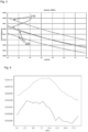
- FIG. 3 represents the release time (on the ordinate) as a function of the amplitude of a balance (on the abscissa) coupled to the anchor 100 from numerical simulations.
- the input data are the movement caliber, the entry penetration, the exit penetration and the wheel torque.
- the output data are amplitude, input clearance time and output clearance time.
- the curve bundles delimit the expected clearance times for 99 penetrations within the tolerances. It is possible to carry out one or more measurement campaigns to obtain more statistical data and thus make the theoretical numerical model more robust.
- the clearance time is greater at the exit (due to the asymmetric lever arms of the anchor) than at the entry.
- the measured times are projected onto the numerical simulation, the reading of the relative position of the point compared to the position of the curves gives a penetration value for the part.
- Curves 210 correspond to the output
- curves 220 correspond to the input.
- the clearance time is a function of the amplitude and the penetration. It is possible to project the measured times onto the digital simulation of the construction of the parts in dynamic version (i.e. with the modeled positions of the different parts, for example using CAD (Computer Aided Design) software), and then reading the relative position of the points on the digital simulation gives a penetration value.
- CAD Computer Aided Design
- the measurement is broken down into signal acquisition and processing.
- the data entered is the acoustic measurement (ac), and possibly the optical measurement (opt) and the caliber data.
- the output data are the oscillation amplitude, the oscillation rate, the oscillation acoustic cue, the oscillation escapement times and the actual lift angle.
- An additional layer of signal processing is applied to calculate the average clearance times over the measurement on the input paddle sound on the tooth and the output paddle sound on the tooth.
- the clearance times are also associated with a tooth index (repetition of the signal every 20 teeth), which allows visualization of the differences in elapsed time 204 between the first two sounds 201, 202 on a wheel revolution 10 which accounts for the out-of-roundness of the escape wheel 10.
- Out-of-roundness also called out-of-round or out-of-round
- the curve at the top of the figure 4 corresponds to the output sound, the bottom curve to the input sound, in this example.
- the numerical value of the penetration is directly calculated by means of the quadratic function.
- the numerical value can also be read from a look-up table resulting from numerical simulation.
- a correction to the calculation is made because the amplitude is corrected by considering the reference defect which unbalances the amplitude of the input sound and the output sound.
- a median of the twenty teeth 11, 13 as a comparison reference. It is possible to define another characteristic for the comparison, as previously mentioned (for example an average, a linear regression, a common characteristic, a representative characteristic, a function of the penetration distances of the pallets of the teeth, without being limited to these), in order to determine whether it is necessary to modify the position of the pallets 101, 102 in the anchor 100, to change the escape wheel 10, the pallets 101, 102 or to carry out any corrective operation.
- the acquisition frequency can influence the measurement resolution. By default, the acquisition is done at 50 kHz, but it is possible to maximize the detection capacity by setting it to 100 kHz.
- the lift angle is a linear function of the penetrations, the greater the penetrations, the longer the balance takes to disengage from the escapement, the greater the lift angle.
- An optical and acoustic coupling of the process makes it possible to calculate a quantity called the real lift angle which is a quantity close to but different from the lift angle.
- a model providing the equivalence between these quantities can make it possible to have a second method of calculating the penetrations as well as a value of the torque available at the escape wheel.
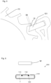
- FIG. 5 represents a detailed view of the penetration 99 of one of the pallets 101, 102 (here pallet 101 for the example) on the tooth in contact 13 among the teeth 11.
- FIG. 6 represents an example of a measuring device for measuring a sound and implementing the diagnostic method.
- the near-field acoustic emission of a watch can be highly variable along its outer shell and that a spatial scan of the near-field acoustic emission provides a plurality of information that allows for better characterization of the acoustic behavior and the noise and emission sources of the watch.
- the inventors also recognized that a measurement based on one or more microphones and a spatial scan provides the best available information in terms of frequency band, because microphones have an inherently wider measurement bandwidth than vibration sensors, and also that a plurality of microphones provides the best available information from weak signal captures, because the combination of a plurality of signal captures inherently brings increased signal-to-noise ratio capability.
- a measuring device 2000 for measuring the sound generated by the watch W may be used, such as the measuring device 2000 having: a support surface 1100, a plurality of microphones 1200 placed on or under the support surface 1100, a controller connected to the plurality of microphones 1200, wherein the controller is configured to process the output of the plurality of microphones 1200 so as to obtain one or more signals representative of the sound generated by the watch W.
- the plurality of microphones 1200 can be placed in close proximity to the object to be measured, such as a watch W, so that environmental noise is limited from reaching the microphones 1200 and the sound of the watch is measured with very high sensitivity and selectivity.
- the plurality of microphones 1200 may be phase and amplitude matched.
- the plurality of microphones 1200 may be configured to have an amplitude shift of less than 3 dB, preferably less than 2 dB, more preferably less than 1 dB, and/or the plurality of microphones 1200 may be configured to have a phase shift of less than 10°, preferably less than 5°, more preferably less than 1°.
- the plurality of microphones 1200 may be MEMS-based microphones.
- the plurality of microphones 1200 may be separated from each other by an intra-microphone distance, the intra-microphone distance being less than 1/2 of the smallest wavelength measured by the measuring device 2000, preferably less than 1/4 of the smallest wavelength, more preferably less than 1/8 of the smallest wavelength.
- the plurality of microphones 1200 may cover a total distance, the total distance may be less than the smallest wavelength measured by the measuring apparatus 2000, preferably less than half of the smallest wavelength.
- the plurality of microphones 1200 may cover a total distance, the total distance may be less than 10 cm, preferably less than 5 cm, more preferably less than 3 cm.
- the plurality of microphones 1200 may include at least 4 microphones, preferably at least 16 microphones, more preferably at least 32 microphones.
- Different microphones 1200 may be configured to measure sounds over different frequency ranges.
- a volume V between the watch and a majority, preferably all, of the microphones may be filled with a liquid and/or gel.
- the watch W to be measured or listened to may be placed at a measurement distance from the plurality of microphones 1200 that may be less than 1 cm, preferably less than 0.5 cm, more preferably less than 1 mm.
- the plurality of microphones 1200 may be configured to implement an acoustic antenna.
- An acoustic antenna may be considered as a device comprising an array of microphones 1200 used to detect sound waves coming from a particular direction.
- a microphone can measure in the bandwidth of 500 Hz to 200 kHz, it can be used to measure sounds in a narrower bandwidth only, such as 500 Hz to 1 kHz, for optimal use.
- the measuring device 2000 may be configured such that the watch W is held at the measuring distance without additional support. This may be achieved by providing a frame suitable for holding the watch W. Alternatively, or in addition, the support surface 1100 of the measuring device 2000 may be configured to hold the watch in place.
- the portion of the measuring device 2000 that holds the watch W in place may have a shape complementary to at least a portion of the outer shape of the watch, such that the watch may be held firmly and securely, while reducing the amount of ambient noise reaching the microphone(s) due to the complementarity of the support structure and the shape of the watch, as will be illustrated with reference to the figure 7 .
- the measuring device 2000 may also include a housing 2100 configured to define a volume V.
- the volume V is therefore an internal volume of the housing 2100.
- the housing 2100 may include or be connected to the support surface 1100, such that the plurality of microphones 1200 may be placed inside the volume V.
- the support surface 1100 may comprise at least one opening 1110.
- FIG. 7 represents another example of a measuring device for measuring sound and implementing the diagnostic method.
- the support surface 4100 of the measuring device 2000 may be flexible and/or configured to conform to a surface of the watch W.
- the flexible support surface 4100 may be held in place by a suitable non-flexible support frame 4400, which is only schematically illustrated in FIG. figure 7 .
Landscapes
- Physics & Mathematics (AREA)
- General Physics & Mathematics (AREA)
- Measurement Of Mechanical Vibrations Or Ultrasonic Waves (AREA)
Priority Applications (2)
| Application Number | Priority Date | Filing Date | Title |
|---|---|---|---|
| EP23170978.3A EP4459384A1 (de) | 2023-05-02 | 2023-05-02 | Akustische messung der durchdringung einer palette durch die zähne eines hemmungsrad |
| EP24171653.9A EP4459386A1 (de) | 2023-05-02 | 2024-04-22 | Akustische messungen an einer uhrenhemmung |
Applications Claiming Priority (1)
| Application Number | Priority Date | Filing Date | Title |
|---|---|---|---|
| EP23170978.3A EP4459384A1 (de) | 2023-05-02 | 2023-05-02 | Akustische messung der durchdringung einer palette durch die zähne eines hemmungsrad |
Publications (1)
| Publication Number | Publication Date |
|---|---|
| EP4459384A1 true EP4459384A1 (de) | 2024-11-06 |
Family
ID=86328455
Family Applications (2)
| Application Number | Title | Priority Date | Filing Date |
|---|---|---|---|
| EP23170978.3A Pending EP4459384A1 (de) | 2023-05-02 | 2023-05-02 | Akustische messung der durchdringung einer palette durch die zähne eines hemmungsrad |
| EP24171653.9A Pending EP4459386A1 (de) | 2023-05-02 | 2024-04-22 | Akustische messungen an einer uhrenhemmung |
Family Applications After (1)
| Application Number | Title | Priority Date | Filing Date |
|---|---|---|---|
| EP24171653.9A Pending EP4459386A1 (de) | 2023-05-02 | 2024-04-22 | Akustische messungen an einer uhrenhemmung |
Country Status (1)
| Country | Link |
|---|---|
| EP (2) | EP4459384A1 (de) |
Citations (5)
| Publication number | Priority date | Publication date | Assignee | Title |
|---|---|---|---|---|
| FR2767205A1 (fr) * | 1997-08-07 | 1999-02-12 | Femto | Procede pour mesurer des parametres d'une montre mecanique et dispositif pour sa mise en oeuvre |
| CH691992A5 (fr) | 1997-07-28 | 2001-12-14 | Femto | Procédé pour mesurer un angle que parcourt le balancier d'une montre mécanique et son amplitude et dispositif pour sa mise en oeuvre. |
| CH716023A2 (fr) * | 2019-03-28 | 2020-09-30 | Seiko Instr Inc | Programme d'évaluation d'état et bracelet de montre pour exécuter le programme. |
| EP3812847A1 (de) * | 2019-10-21 | 2021-04-28 | The Swatch Group Research and Development Ltd | Messsystem für mehrere mechanische uhrwerke |
| CH717263A1 (fr) | 2020-03-27 | 2021-09-30 | Richemont Int Sa | Loupe électronique d'horloger, ensemble de loupe électronique d'horloger et procédé pour effectuer un contrôle d'un produit horloger, notamment d'un mécanisme de montre. |
-
2023
- 2023-05-02 EP EP23170978.3A patent/EP4459384A1/de active Pending
-
2024
- 2024-04-22 EP EP24171653.9A patent/EP4459386A1/de active Pending
Patent Citations (5)
| Publication number | Priority date | Publication date | Assignee | Title |
|---|---|---|---|---|
| CH691992A5 (fr) | 1997-07-28 | 2001-12-14 | Femto | Procédé pour mesurer un angle que parcourt le balancier d'une montre mécanique et son amplitude et dispositif pour sa mise en oeuvre. |
| FR2767205A1 (fr) * | 1997-08-07 | 1999-02-12 | Femto | Procede pour mesurer des parametres d'une montre mecanique et dispositif pour sa mise en oeuvre |
| CH716023A2 (fr) * | 2019-03-28 | 2020-09-30 | Seiko Instr Inc | Programme d'évaluation d'état et bracelet de montre pour exécuter le programme. |
| EP3812847A1 (de) * | 2019-10-21 | 2021-04-28 | The Swatch Group Research and Development Ltd | Messsystem für mehrere mechanische uhrwerke |
| CH717263A1 (fr) | 2020-03-27 | 2021-09-30 | Richemont Int Sa | Loupe électronique d'horloger, ensemble de loupe électronique d'horloger et procédé pour effectuer un contrôle d'un produit horloger, notamment d'un mécanisme de montre. |
Also Published As
| Publication number | Publication date |
|---|---|
| EP4459386A1 (de) | 2024-11-06 |
Similar Documents
| Publication | Publication Date | Title |
|---|---|---|
| EP2304391B1 (de) | Optische anordnung und verfahren zur messung der drehung eines objekts | |
| FR3073289A1 (fr) | Controle de sante d'une structure industrielle | |
| WO2006013247A1 (fr) | Dispositif optique de mesure de l’epaisseur d’un milieu au moins partiellement transparent | |
| EP3201610A1 (de) | Verfahren und system zur überprüfung transparenter wafer für elektronik, optik und opto-elektronik | |
| EP3724652B1 (de) | Vorrichtung, system und verfahren zur bildgebung von defekten in einer struktur durch senden und empfangen von mechanischen wellen durch die struktur | |
| EP4459384A1 (de) | Akustische messung der durchdringung einer palette durch die zähne eines hemmungsrad | |
| EP4459383A1 (de) | Erkennung eines defekts eines zahns einer uhrenkomponente | |
| WO2023187171A1 (fr) | Procédé et système de caractérisation d'un objectif optique pour la correction d'aberrations optiques introduites par ledit objectif optique dans une image | |
| FR2767205A1 (fr) | Procede pour mesurer des parametres d'une montre mecanique et dispositif pour sa mise en oeuvre | |
| EP3797336B1 (de) | Vorrichtung und verfahren zur erfassung, speicherung, analyse und ausgabe der ergebnisse der analyse von zeitmessdaten | |
| WO2013140065A1 (fr) | Système de mesure d'une zone d'écartement dans un substrat | |
| EP3985457B1 (de) | Einheit zum messen des relativen feuchtigkeitsgrads im gehäuse einer armbanduhr | |
| EP4459385A1 (de) | Akustische erkennung des schmierstands der komponenten eines uhrwerks | |
| WO2023067158A1 (fr) | Procédé de caractérisation fonctionnelle d'objectifs optiques | |
| EP4538806A1 (de) | Verfahren zur bestimmung eines signierten bezugswertes eines oszillators für eine uhr | |
| EP4433792A1 (de) | Verfahren zur herstellung eines geometrischen charakterisierungswerkzeugs für eine optische linse zur herstellung | |
| CH712940B1 (fr) | Méthodes et système pour déterminer certains paramètres liés à l'organe réglant d'une montre. | |
| BE1025565B1 (fr) | Dispositif et methode pour controle non destructif de structures | |
| CH691992A5 (fr) | Procédé pour mesurer un angle que parcourt le balancier d'une montre mécanique et son amplitude et dispositif pour sa mise en oeuvre. | |
| EP4474924B1 (de) | Vorrichtung zur messung des feuchtigkeitsgrades im inneren volumen eines armbanduhrgehäuses | |
| EP2881809B1 (de) | Messverfahren und -gerät der Schwingungsfrequenz und -amplitude eines mechanischen Oszillators in einem Uhrwerk | |
| WO2025119883A1 (fr) | Procédé de controle et de fabrication d'éléments inertiels d'horlogerie | |
| CH704688A2 (fr) | Procédé de certification de montre-chronographe. | |
| WO1999067686A1 (fr) | Procede et appareil pour la mesure du repere d'un mouvement de montre mecanique | |
| CH717974B1 (fr) | Ensemble de mesure du degré d'humidité relative à l'intérieur d'un boîtier d'une montre. |
Legal Events
| Date | Code | Title | Description |
|---|---|---|---|
| PUAI | Public reference made under article 153(3) epc to a published international application that has entered the european phase |
Free format text: ORIGINAL CODE: 0009012 |
|
| STAA | Information on the status of an ep patent application or granted ep patent |
Free format text: STATUS: THE APPLICATION HAS BEEN PUBLISHED |
|
| AK | Designated contracting states |
Kind code of ref document: A1 Designated state(s): AL AT BE BG CH CY CZ DE DK EE ES FI FR GB GR HR HU IE IS IT LI LT LU LV MC ME MK MT NL NO PL PT RO RS SE SI SK SM TR |
|
| STAA | Information on the status of an ep patent application or granted ep patent |
Free format text: STATUS: REQUEST FOR EXAMINATION WAS MADE |
|
| 17P | Request for examination filed |
Effective date: 20250506 |