EP4459757A1 - Sekundärbatteriepack - Google Patents
Sekundärbatteriepack Download PDFInfo
- Publication number
- EP4459757A1 EP4459757A1 EP23903883.9A EP23903883A EP4459757A1 EP 4459757 A1 EP4459757 A1 EP 4459757A1 EP 23903883 A EP23903883 A EP 23903883A EP 4459757 A1 EP4459757 A1 EP 4459757A1
- Authority
- EP
- European Patent Office
- Prior art keywords
- pouch
- secondary battery
- battery pack
- case
- type cells
- Prior art date
- Legal status (The legal status is an assumption and is not a legal conclusion. Google has not performed a legal analysis and makes no representation as to the accuracy of the status listed.)
- Pending
Links
Images




Classifications
-
- H—ELECTRICITY
- H01—ELECTRIC ELEMENTS
- H01M—PROCESSES OR MEANS, e.g. BATTERIES, FOR THE DIRECT CONVERSION OF CHEMICAL ENERGY INTO ELECTRICAL ENERGY
- H01M50/00—Constructional details or processes of manufacture of the non-active parts of electrochemical cells other than fuel cells, e.g. hybrid cells
- H01M50/10—Primary casings; Jackets or wrappings
- H01M50/14—Primary casings; Jackets or wrappings for protecting against damage caused by external factors
-
- H—ELECTRICITY
- H01—ELECTRIC ELEMENTS
- H01M—PROCESSES OR MEANS, e.g. BATTERIES, FOR THE DIRECT CONVERSION OF CHEMICAL ENERGY INTO ELECTRICAL ENERGY
- H01M50/00—Constructional details or processes of manufacture of the non-active parts of electrochemical cells other than fuel cells, e.g. hybrid cells
- H01M50/10—Primary casings; Jackets or wrappings
- H01M50/102—Primary casings; Jackets or wrappings characterised by their shape or physical structure
- H01M50/105—Pouches or flexible bags
-
- H—ELECTRICITY
- H01—ELECTRIC ELEMENTS
- H01M—PROCESSES OR MEANS, e.g. BATTERIES, FOR THE DIRECT CONVERSION OF CHEMICAL ENERGY INTO ELECTRICAL ENERGY
- H01M50/00—Constructional details or processes of manufacture of the non-active parts of electrochemical cells other than fuel cells, e.g. hybrid cells
- H01M50/10—Primary casings; Jackets or wrappings
- H01M50/116—Primary casings; Jackets or wrappings characterised by the material
- H01M50/121—Organic material
-
- H—ELECTRICITY
- H01—ELECTRIC ELEMENTS
- H01M—PROCESSES OR MEANS, e.g. BATTERIES, FOR THE DIRECT CONVERSION OF CHEMICAL ENERGY INTO ELECTRICAL ENERGY
- H01M50/00—Constructional details or processes of manufacture of the non-active parts of electrochemical cells other than fuel cells, e.g. hybrid cells
- H01M50/10—Primary casings; Jackets or wrappings
- H01M50/116—Primary casings; Jackets or wrappings characterised by the material
- H01M50/124—Primary casings; Jackets or wrappings characterised by the material having a layered structure
-
- H—ELECTRICITY
- H01—ELECTRIC ELEMENTS
- H01M—PROCESSES OR MEANS, e.g. BATTERIES, FOR THE DIRECT CONVERSION OF CHEMICAL ENERGY INTO ELECTRICAL ENERGY
- H01M50/00—Constructional details or processes of manufacture of the non-active parts of electrochemical cells other than fuel cells, e.g. hybrid cells
- H01M50/10—Primary casings; Jackets or wrappings
- H01M50/131—Primary casings; Jackets or wrappings characterised by physical properties, e.g. gas permeability, size or heat resistance
- H01M50/133—Thickness
-
- H—ELECTRICITY
- H01—ELECTRIC ELEMENTS
- H01M—PROCESSES OR MEANS, e.g. BATTERIES, FOR THE DIRECT CONVERSION OF CHEMICAL ENERGY INTO ELECTRICAL ENERGY
- H01M50/00—Constructional details or processes of manufacture of the non-active parts of electrochemical cells other than fuel cells, e.g. hybrid cells
- H01M50/20—Mountings; Secondary casings or frames; Racks, modules or packs; Suspension devices; Shock absorbers; Transport or carrying devices; Holders
- H01M50/204—Racks, modules or packs for multiple batteries or multiple cells
- H01M50/207—Racks, modules or packs for multiple batteries or multiple cells characterised by their shape
- H01M50/211—Racks, modules or packs for multiple batteries or multiple cells characterised by their shape adapted for pouch cells
-
- H—ELECTRICITY
- H01—ELECTRIC ELEMENTS
- H01M—PROCESSES OR MEANS, e.g. BATTERIES, FOR THE DIRECT CONVERSION OF CHEMICAL ENERGY INTO ELECTRICAL ENERGY
- H01M50/00—Constructional details or processes of manufacture of the non-active parts of electrochemical cells other than fuel cells, e.g. hybrid cells
- H01M50/20—Mountings; Secondary casings or frames; Racks, modules or packs; Suspension devices; Shock absorbers; Transport or carrying devices; Holders
- H01M50/233—Mountings; Secondary casings or frames; Racks, modules or packs; Suspension devices; Shock absorbers; Transport or carrying devices; Holders characterised by physical properties of casings or racks, e.g. dimensions
- H01M50/24—Mountings; Secondary casings or frames; Racks, modules or packs; Suspension devices; Shock absorbers; Transport or carrying devices; Holders characterised by physical properties of casings or racks, e.g. dimensions adapted for protecting batteries from their environment, e.g. from corrosion
-
- H—ELECTRICITY
- H01—ELECTRIC ELEMENTS
- H01M—PROCESSES OR MEANS, e.g. BATTERIES, FOR THE DIRECT CONVERSION OF CHEMICAL ENERGY INTO ELECTRICAL ENERGY
- H01M50/00—Constructional details or processes of manufacture of the non-active parts of electrochemical cells other than fuel cells, e.g. hybrid cells
- H01M50/20—Mountings; Secondary casings or frames; Racks, modules or packs; Suspension devices; Shock absorbers; Transport or carrying devices; Holders
- H01M50/233—Mountings; Secondary casings or frames; Racks, modules or packs; Suspension devices; Shock absorbers; Transport or carrying devices; Holders characterised by physical properties of casings or racks, e.g. dimensions
- H01M50/242—Mountings; Secondary casings or frames; Racks, modules or packs; Suspension devices; Shock absorbers; Transport or carrying devices; Holders characterised by physical properties of casings or racks, e.g. dimensions adapted for protecting batteries against vibrations, collision impact or swelling
-
- H—ELECTRICITY
- H01—ELECTRIC ELEMENTS
- H01M—PROCESSES OR MEANS, e.g. BATTERIES, FOR THE DIRECT CONVERSION OF CHEMICAL ENERGY INTO ELECTRICAL ENERGY
- H01M50/00—Constructional details or processes of manufacture of the non-active parts of electrochemical cells other than fuel cells, e.g. hybrid cells
- H01M50/30—Arrangements for facilitating escape of gases
-
- H—ELECTRICITY
- H01—ELECTRIC ELEMENTS
- H01M—PROCESSES OR MEANS, e.g. BATTERIES, FOR THE DIRECT CONVERSION OF CHEMICAL ENERGY INTO ELECTRICAL ENERGY
- H01M50/00—Constructional details or processes of manufacture of the non-active parts of electrochemical cells other than fuel cells, e.g. hybrid cells
- H01M50/30—Arrangements for facilitating escape of gases
- H01M50/394—Gas-pervious parts or elements
-
- H—ELECTRICITY
- H01—ELECTRIC ELEMENTS
- H01M—PROCESSES OR MEANS, e.g. BATTERIES, FOR THE DIRECT CONVERSION OF CHEMICAL ENERGY INTO ELECTRICAL ENERGY
- H01M50/00—Constructional details or processes of manufacture of the non-active parts of electrochemical cells other than fuel cells, e.g. hybrid cells
- H01M50/40—Separators; Membranes; Diaphragms; Spacing elements inside cells
- H01M50/471—Spacing elements inside cells other than separators, membranes or diaphragms; Manufacturing processes thereof
- H01M50/474—Spacing elements inside cells other than separators, membranes or diaphragms; Manufacturing processes thereof characterised by their position inside the cells
-
- H—ELECTRICITY
- H01—ELECTRIC ELEMENTS
- H01M—PROCESSES OR MEANS, e.g. BATTERIES, FOR THE DIRECT CONVERSION OF CHEMICAL ENERGY INTO ELECTRICAL ENERGY
- H01M50/00—Constructional details or processes of manufacture of the non-active parts of electrochemical cells other than fuel cells, e.g. hybrid cells
- H01M50/40—Separators; Membranes; Diaphragms; Spacing elements inside cells
- H01M50/471—Spacing elements inside cells other than separators, membranes or diaphragms; Manufacturing processes thereof
- H01M50/477—Spacing elements inside cells other than separators, membranes or diaphragms; Manufacturing processes thereof characterised by their shape
-
- H—ELECTRICITY
- H01—ELECTRIC ELEMENTS
- H01M—PROCESSES OR MEANS, e.g. BATTERIES, FOR THE DIRECT CONVERSION OF CHEMICAL ENERGY INTO ELECTRICAL ENERGY
- H01M50/00—Constructional details or processes of manufacture of the non-active parts of electrochemical cells other than fuel cells, e.g. hybrid cells
- H01M50/40—Separators; Membranes; Diaphragms; Spacing elements inside cells
- H01M50/471—Spacing elements inside cells other than separators, membranes or diaphragms; Manufacturing processes thereof
- H01M50/48—Spacing elements inside cells other than separators, membranes or diaphragms; Manufacturing processes thereof characterised by the material
- H01M50/486—Organic material
-
- H—ELECTRICITY
- H01—ELECTRIC ELEMENTS
- H01M—PROCESSES OR MEANS, e.g. BATTERIES, FOR THE DIRECT CONVERSION OF CHEMICAL ENERGY INTO ELECTRICAL ENERGY
- H01M50/00—Constructional details or processes of manufacture of the non-active parts of electrochemical cells other than fuel cells, e.g. hybrid cells
- H01M50/50—Current conducting connections for cells or batteries
- H01M50/572—Means for preventing undesired use or discharge
- H01M50/584—Means for preventing undesired use or discharge for preventing incorrect connections inside or outside the batteries
- H01M50/586—Means for preventing undesired use or discharge for preventing incorrect connections inside or outside the batteries inside the batteries, e.g. incorrect connections of electrodes
-
- H—ELECTRICITY
- H01—ELECTRIC ELEMENTS
- H01M—PROCESSES OR MEANS, e.g. BATTERIES, FOR THE DIRECT CONVERSION OF CHEMICAL ENERGY INTO ELECTRICAL ENERGY
- H01M50/00—Constructional details or processes of manufacture of the non-active parts of electrochemical cells other than fuel cells, e.g. hybrid cells
- H01M50/50—Current conducting connections for cells or batteries
- H01M50/572—Means for preventing undesired use or discharge
- H01M50/584—Means for preventing undesired use or discharge for preventing incorrect connections inside or outside the batteries
- H01M50/59—Means for preventing undesired use or discharge for preventing incorrect connections inside or outside the batteries characterised by the protection means
- H01M50/593—Spacers; Insulating plates
-
- Y—GENERAL TAGGING OF NEW TECHNOLOGICAL DEVELOPMENTS; GENERAL TAGGING OF CROSS-SECTIONAL TECHNOLOGIES SPANNING OVER SEVERAL SECTIONS OF THE IPC; TECHNICAL SUBJECTS COVERED BY FORMER USPC CROSS-REFERENCE ART COLLECTIONS [XRACs] AND DIGESTS
- Y02—TECHNOLOGIES OR APPLICATIONS FOR MITIGATION OR ADAPTATION AGAINST CLIMATE CHANGE
- Y02E—REDUCTION OF GREENHOUSE GAS [GHG] EMISSIONS, RELATED TO ENERGY GENERATION, TRANSMISSION OR DISTRIBUTION
- Y02E60/00—Enabling technologies; Technologies with a potential or indirect contribution to GHG emissions mitigation
- Y02E60/10—Energy storage using batteries
Definitions
- the present disclosure relates to a secondary battery pack. More specifically, the disclosure relates to a secondary battery pack comprising pouch-type cells.
- a secondary battery utilizes lithium ions to charge and discharge, and can store and supply electrical energy.
- the secondary battery may be used in the form of a pack comprising a plurality of cells.
- the plurality of cells may change in volume as charging and discharging proceeds.
- a secondary battery using a silicon negative electrode, a secondary battery using lithium metal, and the like suffer from the problem that the thickness of the negative electrode changes by about 10% during charging and discharging. This problem occurs in most secondary batteries, including lithium ion secondary batteries, all-solid-state secondary batteries, semi-solid-state secondary batteries, and lithium-sulfur secondary batteries.
- Cylindrical and prismatic cells each have a fixed case shape, which makes it relatively impossible to apply constant pressure to the cell.
- prismatic cells may be more susceptible to swelling defects, where the wide sides of the battery bulge, unlike cylindrical cells, without a special pressurization device.
- the pouch-type cells have a variable case size
- the pouch-type cells can be subjected to a constant pressure from the outside even if the size of the pouch-type cells changes, and in terms of weight and safety, the use of pouch-type cells in secondary battery packs is being considered for light cell weight (high energy density).
- pouch-type cells contain metal to prevent moisture permeation and enhance impact resistance, it is difficult to achieve high energy density in secondary battery packs containing pouch-type cells.
- Patent Document 1 Korean Laid-Open Publication No. 10-2022-0125096
- the present invention is proposed to address the above problems, and it is an objective of the present disclosure to provide a secondary battery pack that has improved energy density, is impact resistant, and can prevent the penetration of moisture or oxygen.
- a secondary battery pack comprising: at least one pouch-type cell; and a case having an interior space to receive the pouch-type cell, wherein the at least one pouch-type cell each comprises an electrode assembly and a pouch film to receive the electrode assembly, and the pouch film consists of a polymer only or a polymer and adhesive only.
- a secondary battery pack wherein the pouch film has a thickness of from 20 ⁇ m to 200 ⁇ m.
- a secondary battery pack wherein the pouch film has a weight per area of between 20 g/m 2 and 150 g/m 2 .
- a secondary battery pack wherein the polymer comprises at least one selected from a group consisting of: nylon, polyethylene, polyamide, polyamide nylon, polypropylene, polyimide, polyvinyl chloride, polyethylene terephthalate, olefin resin, polystyrene, polycarbonate and polyvinyl alcohol.
- a secondary battery pack further comprising spacers disposed on sides of the pouch-type cells inside the case, wherein the spacer is a polymer, metal, or elastomer.
- a secondary battery pack wherein the polymer comprises rubber.
- a secondary battery pack wherein the elastomer is a leaf spring.
- a secondary battery pack wherein a positive electrode terminal, a negative electrode terminal, and a gas outlet are arranged on a top surface of the case, and the positive electrode terminal and the negative electrode terminal each is electrically connected with the pouch-type cells.
- a positive electrode terminal is disposed on a top surface of the case and a negative electrode terminal is disposed on a bottom surface of the case
- the positive electrode terminal and the negative electrode terminal are each electrically connected with the pouch-type cells
- a gas outlet is disposed on at least one of the top surface and the bottom surface of the case.
- the secondary battery pack according to an embodiment of the present disclosure can achieve a higher energy density than conventionally available. Furthermore, by using an impact-resistant case, the pouch-type cells, which do not contain metal, can be protected from impact. Furthermore, by using a casing, external moisture or oxygen can be prevented from accessing the pouch-type cells. Furthermore, because the pouch is composed of polymer, it can be formed thicker and still have a low weight, and it can accommodate the electrode assembly even if tears occur during the process of molding the shape of the pouch.
- FIG. 1 is a drawing depicting a pouch-type cell, according to an embodiment of the present disclosure.
- a pouch-type cell 100a includes an electrode assembly 120b comprising alternately stacked electrodes and separators, and a pouch 110 for receiving the electrode assembly, wherein the pouch 110 may be constructed of a polymer.
- the composition and structure of the pouch 110 will be described later.
- the electrode assembly 120b is a power generation element capable of being charged and discharged, comprising an alternating stack of electrodes and separators, wherein the electrodes include positive electrodes and negative electrodes, and wherein the positive electrodes, the separators, and the negative electrodes may be disposed alternately.
- the electrode assembly 120b may have electrode tabs 120a, 120c connected to one end thereof.
- the electrode tabs 120a, 120c may be connected to only one surface of the electrode assembly 120b.
- One of the electrode tabs 120a, 120c may be an electrode tab connected to positive electrodes, and the other may be an electrode tab connected to negative electrodes.
- the electrode assembly 120b may be electrically connected to an external device.
- the pouch 110 may accommodate the electrode assembly 120b.
- the pouch 110 may have an internal space for receiving the electrode assembly 120b.
- Conventional pouches have a structure comprising an aluminum alloy thin film and a polymer laminated to the aluminum alloy thin film.
- the conventional pouch includes the aluminum alloy thin film, it was possible to secure a certain level of mechanical strength while preventing external gas or moisture from penetrating into the electrode assembly 120b.
- the aluminum alloy thin film increased the weight of the pouch-type cell 100a, making it difficult to secure energy density.
- FIG. 2 is a drawing illustrating a pouch-type cell, according to another embodiment of the present disclosure.
- a pouch-type cell 100b may include an electrode assembly 130b comprising alternating stacked layers of electrodes and separators, and a pouch 110 for receiving the electrode assembly and electrolyte, wherein the pouch 110 may be constructed of a polymer.
- the composition and structure of the pouch 110 will be described later.
- the electrode assembly 130b containing the electrolyte is a chargeable and dischargeable power generation device, comprising an alternating stack of electrodes and separators, wherein the electrodes include positive electrodes and negative electrodes, wherein the positive electrodes, the separators, and the negative electrodes are alternately located and may contain an electrolyte in the internal pores.
- the electrode assembly 130b may have electrode tabs 130a, 130c connected to the ends thereof.
- the electrode tabs 130a, 130c may be connected to both ends of the electrode assembly 130b.
- One of the electrode tabs 130a, 130c may be an electrode tab connected to positive electrodes, and the other may be an electrode tab connected to negative electrodes.
- the electrode assembly 130b may be electrically connected to an external device.
- the pouch 110 can accommodate the electrode assembly 130b and the electrolyte.
- the pouch 110 may have an internal space for receiving the electrode assembly 130b and the electrolyte.
- Prior art pouches have a structure comprising an aluminum alloy thin film and a polymer laminated to the aluminum alloy thin film.
- the conventional pouch includes the aluminum alloy thin film, it is possible to secure a certain level of mechanical strength while preventing external gas or moisture from penetrating into the electrode assembly 130b.
- the aluminum alloy thin film increased the weight of the pouch-type cell 100b, making it difficult to secure energy density.
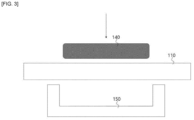
- FIGS. 3 and 4 are drawings illustrating a step in fabricating a pouch for the pouch-type cell of FIG. 1 .
- the pouch 110 may include an interior space 115 for receiving the electrode assembly described above.
- the lower mold 150 and punch mold 140 can be used to apply pressure to the pouch 110 to form the interior space 115. Since the pouch 110 according to an embodiment of the present disclosure is composed solely of the polymer, the interior space 115 can be formed more easily than when including the aluminum alloy thin film. Furthermore, because the prior art pouches include the aluminum alloy thin film, they are made with a reduced thickness to achieve a high energy density. Such conventional pouches suffer from tearing due to being caught by the corners of the lower mold 150, etc. during the process of applying pressure to form the interior space. In this case, the pouch is inadequate to accommodate the electrode assembly.
- the pouch 110 since the pouch 110 according to an embodiment of the present disclosure does not include the aluminum alloy thin film, it can be fabricated using the polymer to a similar thickness and still not tear. Thus, even if the pouch 110 is not thick and heavy, it can still be used to accommodate the electrode assembly.
- the thickness of the pouch 110 may be from 20 ⁇ m to 200 ⁇ m, and preferably from 50 ⁇ m to 150 ⁇ m.
- the pouch 110 may be a single layer of polymer, or may be formed by laminating a plurality of polymers.
- the polymer may be one or more of nylon, polyethylene, polyamide, polyamide nylon, polypropylene, polyimide, polyvinyl chloride, polyethylene terephthalate, olefin resin, polystyrene, polycarbonate and polyvinyl alcohol.
- these polymer layers may be multilayered to form an adhesive film on one surface for adhesion of the film.
- the material of the adhesive film may be an adhesive film for use in a conventional pouch for a secondary battery.
- it may comprise an adhesive layer, a polyimide layer, and a nylon layer in the direction from the bottom to the top.
- the polyimide layer may be composed of a polyimide material
- the nylon layer may be composed of a nylon material.
- a pouch-type cell comprising the pouch 110 can achieve a high energy density.
- the pouch 110 according to an embodiment of the present disclosure has a weight per area of about 150 g/m 2 or less, and a secondary battery pack including the pouch-type cell can have a pack energy density of 240 Wh/kg or more. If the weight per area of the pouch 110 exceeds 150 g/m 2 , the pack energy density will fall below 240 Wh/kg and the energy density advantage of the secondary battery pack according to an embodiment of the present disclosure will be lost. If the weight per area of the pouch 110 is less than 20 g/m 2 , it may be too thin and the film may lack rigidity, causing leakage of electrolyte.
- FIGS. 5 and 6 are drawings illustrating an embodiment of a secondary battery pack including the pouch-type cells of FIG. 1 .
- a secondary battery pack 200 may include a case 210, a positive electrode terminal 220, a negative electrode terminal 230, a gas outlet 240, a spacer 250, and a plurality of pouch-type cells 260.
- the plurality of pouch-type cells 260 may be substantially the same as those of the pouch-type cells described above, such as the unidirectional tab pouch-type cells (see FIG. 1 ).
- the case 210 may include a plurality of pouch-type cells 260 inside. The number of the plurality of pouch-type cells 260 is not limited, and different numbers may be selected and used as needed.
- the case 210 may be constructed of a material having rigidity.
- the case 210 may be constructed of stainless steel, an aluminum alloy containing at least 50% aluminum, a magnesium alloy containing at least 50% magnesium, a titanium alloy containing at least 50% titanium, or the like.
- the case 210 may serve to protect the plurality of pouch-type cells 260 from external impact and to prevent moisture from penetrating into the plurality of pouch-type cells 260. Due to the case 210, the plurality of pouch-type cells 260 may be protected from external impact or moisture intrusion, even if the aluminum alloy thin film is not used.
- the case 210 can have four sides, and a pair of sides facing each other can have a larger area than the other pair of sides facing each other.
- one pair of sides may be equal to or more than twice as wide as the other pair of sides.
- the positive electrode terminal 220 and the negative electrode terminal 230 may each be connected to the electrode tabs of the plurality of pouch-type cells 260 by separate connecting members 215, 225.
- the connecting members 215, 225 can be any electrically conductive material.
- the gas outlet 240 can vent gases generated during operations of the secondary battery pack 200.
- a structure including the connecting members 215, 225, the positive electrode terminal 220, the negative electrode terminal 230, and the gas outlet 240 may be defined as a top assembly.
- the gas outlet 240 is shown disposed on a top surface of the case 210, but this is exemplary and the gas outlet 240 may be disposed on a bottom surface of the case 210, or may be disposed on both a top surface and a bottom surface of the case 210.
- the spacers 250 may be disposed at outermost positions of the plurality of pouch-type cells 260, and may be in the form of a porous foam of a polymer (e.g., rubber) and metal, or an elastomer (e.g., leaf spring).
- the spacers 250 may decrease in volume in response to changes in pressure generated by the plurality of pouch-type cells 260.
- the spacers 250 may decrease in thickness by 5 to 90% at a pressure of about 10 atm. With the spacers 250 and a rigid case 210, a range of pressures can be applied to the plurality of pouch-type cells 260 even as volume changes occur within the interior of the case 210 without external pressure.
- the secondary battery pack 200 can withstand internal pressure generated from the plurality of pouch-type cells 260 without deforming the case 210 by reducing the area where pressure is generated.
- the secondary battery pack 200 includes the spacers 250, it can maintain a constant range of pressure even as the thickness of the pouch-type cell 260 varies within the cell, without the need for an external device, which is advantageous for weight reduction.
- a bulkhead may be present between each of the plurality of pouch-type cells 260.
- the bulkhead may comprise the same material as the spacers 250 and may decrease in volume in response to changes in pressure generated in each of the plurality of pouch-type cells 260.
- the bulkhead may be defined substantially as a spacer.
- the bulkheads may be disposed between each of the plurality of pouch-type cells 260, but may be disposed between only some of the pouch-type cells 260.
- the plurality of pouch-type cells 260 can be physically separated from each other, and in the event of venting due to swelling, the location of the venting can be controlled, thereby preventing cell to cell propagation of fire between the pouch-type cells 260.
- FIGS. 7 and 8 are drawings illustrating another embodiment of a secondary battery pack including the pouch-type cells of FIG. 2 .
- a secondary battery pack 300 may include a case 310, a positive electrode terminal 320, a negative electrode terminal 330, a gas outlet 340, a spacer 350, and a plurality of pouch-type cells 360.
- the plurality of pouch-type cells 360 may be substantially the same as any of the pouch-type cells described above, such as the unidirectional tab pouch-type cells (see FIG. 1 ).
- the case 310 may include a plurality of pouch-type cells 360 inside. The number of the plurality of pouch-type cells 360 is not limited, and different numbers may be selected and used as needed.
- the case 310 may be constructed of a material having rigidity.
- the case 310 may be constructed of stainless steel, an aluminum alloy containing at least 50% aluminum, a magnesium alloy containing at least 50% magnesium, a titanium alloy containing at least 50% titanium, or the like.
- the case 310 may serve to protect the plurality of pouch-type cells 360 from external impact and to prevent moisture from penetrating into the plurality of pouch-type cells 360. Due to the case 310, the plurality of pouch-type cells 360 may be protected from external impact or moisture intrusion, even if the aluminum alloy thin film is not used.
- the case 310 can have four sides, and a pair of sides facing each other can have a larger area than the other pair of sides facing each other.
- one pair of sides may be more than twice as wide as the other pair of sides.
- the positive electrode terminals 320 and negative electrode terminals 330 may each be connected to electrode tabs of the plurality of pouch-type cells 360 by separate connecting members 315, 325.
- the connecting members 315, 325 can be any electrically conductive material.
- the gas outlet 340 may vent gases generated during operation of the secondary battery pack 300.
- a structure including the connecting members 315, 325, the positive electrode terminal 320, and the gas outlet 340 may be defined as a top assembly.
- the negative electrode terminal 330 is not included in the top assembly because it is disposed on the lower portion of the case 310.
- the gas outlet 340 is shown disposed on the top surface of the case 310, this is exemplary and the gas outlet 340 may be disposed on the bottom surface of the case 310, or may be disposed on both the top and bottom surfaces of the case 310.
- the spacers 350 may be disposed at outermost positions of the plurality of pouch-type cells 360, and may be in the form of polymer, rubber, metal foam, or leaf springs.
- the spacers 350 may decrease in volume in response to changes in pressure generated by the plurality of pouch-type cells 360.
- the spacers 350 may decrease in thickness by 5 to 90% at a pressure of about 10 atm. With the spacers 350 and a rigid case 310, a certain range of pressure can be applied to the plurality of pouch-type cells 360 even as volume changes occur inside the case 310 without external pressure.
- the secondary battery pack 300 is able to withstand internal pressure generated from the plurality of pouch-type cells 360 without deforming the case 310 by reducing the area where pressure is generated.
- the secondary battery pack 300 includes the spacers 350, it can maintain a constant range of pressure even as the thickness of the pouch-type cells 360 varies within the cell, without the need for an external device, which is advantageous for weight reduction.
- bulkheads may be present between each of the plurality of pouch-type cells 360.
- the bulkheads may comprise the same material as the spacers 350 and may decrease in volume in response to changes in pressure generated in each of the plurality of pouch-type cells 360.
- the bulkheads may be disposed between all of the plurality of pouch-type cells 360, but may also be disposed between only some of the pouch-type cells 360.
- Embodiment 1 and Comparative Example 1 each use 20 pouch-type cells, while Comparative Example 2 uses cylindrical cells.
- Embodiment 1 used a pouch made of nylon (thickness 100 ⁇ m), rubber foam spacers (weight 9.4 g), and a stainless steel case (thickness 0.2 t, 100*600*400 mm), while Comparative Example 1 used a pouch containing an aluminum alloy thin film (thickness 150 ⁇ m, aluminum thickness 80 ⁇ m, polymer insulation layer and adhesive layer 70 ⁇ m).
- Embodiment 1 Comparative Example 1 (pouch-type) Comparative Example 2 (cylinder-type) Unit Cell capacity 32 1.6 3.8 Ah Cell Energy 68 3.4 8.1 Wh 20 cell weight 195 217 -. 9 Weight of Metal Case 34.7 -. -. 9 Top Assembly Weight 5 -. -. 9 Spacer weight 9.4 -. -. 9 Cell Energy Density 280 315 226 Wh/kg Pack/Cell Energy Density Ratio 90 75 90 B Secondary battery pack energy density 252 236 204 Wh/kg
- a secondary battery pack according to an embodiment of the present disclosure has a higher cell energy density and a higher pack energy density than a secondary battery pack according to a comparative example.
- the secondary battery pack has a higher pack energy density because it does not need to separately include a pad or pressurization device.
- the secondary battery pack design complexity is reduced and safety is improved with the existence of a metal case and a gas outlet.
- the secondary battery pack according to Comparative Example 2 uses cylinder-type cells and therefore has the lowest energy density due to the metal case applied to each cylinder-type cell.
- Embodiment 1 Comparative Example 1 Comparative Example 2 Cell deformation in the presence of trace gases X ⁇ X Controllability of vent positions X X X Existence of Metal case ⁇ X ⁇ Existence of In-pack bulkheads ⁇ X X Controllability of cell volume changes ⁇ X X
- Embodiment 1 allows control of cell volume changes due to the metal case and in-pack bulkhead.
- Comparative Example 1 lacks a metal casing and in-pack bulkheads, making cell volume changes less controllable.
- Embodiment 2 used 2 mm thick rubber foam spacers, while Comparative Example 3 did not use spacers.
- Embodiment 2 and Comparative Example 3 were conducted using lithium sulfur battery pouch cells at 400 Wh/kg, and residual capacity was compared by driving charge and discharge cycles at 0.3C discharge and 0.2C charge. The comparison results are shown in Table 3 below. [Table 3] Cycles Embodiment 2 Comparative Example 3 5 100 100 50 95.7 96.2 100 95 89.9 150 92.8 87.4
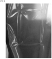
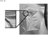
- Cup molding was performed on the pouches of Embodiment 1 and Comparative Example 1 to a depth of 6 mm or more. As a result of the molding, it was found that in the case of embodiment 1, which uses nylon as in the present invention, the pouch was not torn despite the cup molding and a cup was formed (see FIG. 9 ). However, in the case of Comparative Example 1 using an aluminum pouch, tearing occurred when forming the cup (see FIG. 10 ).
Landscapes
- Chemical & Material Sciences (AREA)
- Chemical Kinetics & Catalysis (AREA)
- Electrochemistry (AREA)
- General Chemical & Material Sciences (AREA)
- Sealing Battery Cases Or Jackets (AREA)
- Gas Exhaust Devices For Batteries (AREA)
- Battery Mounting, Suspending (AREA)
Applications Claiming Priority (2)
| Application Number | Priority Date | Filing Date | Title |
|---|---|---|---|
| KR1020220172846A KR20240087284A (ko) | 2022-12-12 | 2022-12-12 | 이차 전지 팩 |
| PCT/KR2023/020074 WO2024128680A1 (ko) | 2022-12-12 | 2023-12-07 | 이차 전지 팩 |
Publications (2)
| Publication Number | Publication Date |
|---|---|
| EP4459757A1 true EP4459757A1 (de) | 2024-11-06 |
| EP4459757A4 EP4459757A4 (de) | 2025-08-06 |
Family
ID=91485255
Family Applications (1)
| Application Number | Title | Priority Date | Filing Date |
|---|---|---|---|
| EP23903883.9A Pending EP4459757A4 (de) | 2022-12-12 | 2023-12-07 | Sekundärbatteriepack |
Country Status (6)
| Country | Link |
|---|---|
| US (1) | US20260011827A1 (de) |
| EP (1) | EP4459757A4 (de) |
| JP (1) | JP2025506534A (de) |
| KR (1) | KR20240087284A (de) |
| CN (1) | CN118661315A (de) |
| WO (1) | WO2024128680A1 (de) |
Families Citing this family (1)
| Publication number | Priority date | Publication date | Assignee | Title |
|---|---|---|---|---|
| KR20260005481A (ko) | 2024-07-03 | 2026-01-12 | 주식회사 엘지에너지솔루션 | 냉각 장치 및 이를 포함하는 배터리 팩 |
Family Cites Families (13)
| Publication number | Priority date | Publication date | Assignee | Title |
|---|---|---|---|---|
| JP5837271B2 (ja) * | 2006-03-30 | 2015-12-24 | 大日本印刷株式会社 | 電池モジュール |
| KR101222397B1 (ko) * | 2010-06-08 | 2013-01-16 | 삼성에스디아이 주식회사 | 배터리 팩 |
| JP5576830B2 (ja) * | 2011-06-09 | 2014-08-20 | 株式会社サンケイ技研 | 携帯型マグネシウム・空気電池 |
| US9172079B2 (en) * | 2012-02-01 | 2015-10-27 | Samsung Sdi Co., Ltd. | Rechargeable battery |
| EP4668405A3 (de) * | 2015-06-18 | 2026-03-25 | 24M Technologies, Inc. | Einzelbeutelbatteriezellen und verfahren zur herstellung |
| JP6597027B2 (ja) * | 2015-07-30 | 2019-10-30 | 大日本印刷株式会社 | 電池、及び電池素子を収容するための包装材料 |
| KR102003019B1 (ko) * | 2017-12-21 | 2019-07-24 | 율촌화학 주식회사 | 배리어 특성이 우수한 폴리프로필렌계 필름 및 이를 포함하는 셀 파우치 |
| JP6904939B2 (ja) * | 2018-11-08 | 2021-07-21 | 積水化学工業株式会社 | 蓄電池モジュール |
| KR102389409B1 (ko) * | 2019-02-25 | 2022-04-22 | 주식회사 엘지에너지솔루션 | 벤팅 장치 |
| CN114144924A (zh) * | 2019-08-06 | 2022-03-04 | 日本碍子株式会社 | 碱性二次电池及碱性二次电池模块 |
| KR20210063939A (ko) * | 2019-11-25 | 2021-06-02 | 주식회사 엘지에너지솔루션 | 배터리 모듈 |
| US12401080B2 (en) * | 2020-11-05 | 2025-08-26 | Lg Energy Solution, Ltd. | Method of setting cell pressure range for secondary battery module |
| KR102790884B1 (ko) | 2021-03-04 | 2025-04-04 | 주식회사 엘지에너지솔루션 | 파우치 포밍 방법 |
-
2022
- 2022-12-12 KR KR1020220172846A patent/KR20240087284A/ko active Pending
-
2023
- 2023-12-07 JP JP2024548645A patent/JP2025506534A/ja active Pending
- 2023-12-07 WO PCT/KR2023/020074 patent/WO2024128680A1/ko not_active Ceased
- 2023-12-07 CN CN202380022481.3A patent/CN118661315A/zh active Pending
- 2023-12-07 US US18/880,262 patent/US20260011827A1/en active Pending
- 2023-12-07 EP EP23903883.9A patent/EP4459757A4/de active Pending
Also Published As
| Publication number | Publication date |
|---|---|
| CN118661315A (zh) | 2024-09-17 |
| JP2025506534A (ja) | 2025-03-11 |
| WO2024128680A1 (ko) | 2024-06-20 |
| US20260011827A1 (en) | 2026-01-08 |
| KR20240087284A (ko) | 2024-06-19 |
| EP4459757A4 (de) | 2025-08-06 |
Similar Documents
| Publication | Publication Date | Title |
|---|---|---|
| US6558438B1 (en) | Method for producing a pressurized package for a film packed battery | |
| CN102884665B (zh) | 改进的堆叠型电池胞或者双电池胞、用于使用该电池胞的二次电池的电极组件及其制造方法 | |
| US6387567B1 (en) | Secondary battery | |
| KR101863431B1 (ko) | 조전지용 스페이서 및 조전지 | |
| US9653749B2 (en) | Secondary battery and secondary battery pack having the same | |
| EP3639316A1 (de) | Gestapelte prismatische architektur für elektrochemische zelle | |
| EP2325918B1 (de) | Sekundärbatterie | |
| US20230135785A1 (en) | Battery module including swelling relief unit | |
| KR102308423B1 (ko) | 형상 기억 합금체가 형성되어 있는 탑 캡을 구비하는 전지셀 | |
| WO2011037335A2 (ko) | 이차 전지 및 그 제조 방법 | |
| KR100954031B1 (ko) | 젤리롤 형 전극 조립체를 가지는 이차전지 | |
| EP4459757A1 (de) | Sekundärbatteriepack | |
| KR101482385B1 (ko) | 단면 음극을 포함하는 단차를 갖는 전극 조립체 | |
| CN116349064A (zh) | 软包型电池壳体、其成型设备及软包型二次电池 | |
| KR102859963B1 (ko) | 전극 조립체 | |
| US11322799B2 (en) | Electrode including single-sided electrode with inorganic coating layer attached to slurry on collector and electrode assembly including the same | |
| EP4618278A1 (de) | Batteriezelle, batterie und elektrische vorrichtung | |
| KR101137633B1 (ko) | 이차 전지 | |
| EP4528907B1 (de) | Sekundärbatterie | |
| EP4571948A1 (de) | Batteriezelle und batteriemodul damit | |
| KR20210152333A (ko) | 전극 조립체 및 이를 포함하는 이차전지 | |
| EP4679571A1 (de) | Sekundärbatterie | |
| EP4290654A1 (de) | Sekundärbatterie | |
| US20260011896A1 (en) | Battery assembly | |
| US20250293406A1 (en) | Battery cell, battery, electric device, and manufacturing method of battery cell |
Legal Events
| Date | Code | Title | Description |
|---|---|---|---|
| STAA | Information on the status of an ep patent application or granted ep patent |
Free format text: STATUS: THE INTERNATIONAL PUBLICATION HAS BEEN MADE |
|
| PUAI | Public reference made under article 153(3) epc to a published international application that has entered the european phase |
Free format text: ORIGINAL CODE: 0009012 |
|
| STAA | Information on the status of an ep patent application or granted ep patent |
Free format text: STATUS: REQUEST FOR EXAMINATION WAS MADE |
|
| 17P | Request for examination filed |
Effective date: 20240730 |
|
| AK | Designated contracting states |
Kind code of ref document: A1 Designated state(s): AL AT BE BG CH CY CZ DE DK EE ES FI FR GB GR HR HU IE IS IT LI LT LU LV MC ME MK MT NL NO PL PT RO RS SE SI SK SM TR |
|
| A4 | Supplementary search report drawn up and despatched |
Effective date: 20250709 |
|
| RIC1 | Information provided on ipc code assigned before grant |
Ipc: H01M 50/121 20210101AFI20250703BHEP Ipc: H01M 50/242 20210101ALI20250703BHEP Ipc: H01M 50/24 20210101ALI20250703BHEP Ipc: H01M 50/105 20210101ALI20250703BHEP Ipc: H01M 50/133 20210101ALI20250703BHEP Ipc: H01M 50/593 20210101ALI20250703BHEP Ipc: H01M 50/586 20210101ALI20250703BHEP Ipc: H01M 50/30 20210101ALI20250703BHEP Ipc: H01M 50/211 20210101ALI20250703BHEP |
|
| DAV | Request for validation of the european patent (deleted) | ||
| DAX | Request for extension of the european patent (deleted) | ||
| STAA | Information on the status of an ep patent application or granted ep patent |
Free format text: STATUS: EXAMINATION IS IN PROGRESS |