EP4459763A1 - Sammelschienenrahmenanordnung und batteriemodul damit - Google Patents
Sammelschienenrahmenanordnung und batteriemodul damit Download PDFInfo
- Publication number
- EP4459763A1 EP4459763A1 EP23820002.6A EP23820002A EP4459763A1 EP 4459763 A1 EP4459763 A1 EP 4459763A1 EP 23820002 A EP23820002 A EP 23820002A EP 4459763 A1 EP4459763 A1 EP 4459763A1
- Authority
- EP
- European Patent Office
- Prior art keywords
- batteries
- bus bar
- buffer member
- bar frame
- battery
- Prior art date
- Legal status (The legal status is an assumption and is not a legal conclusion. Google has not performed a legal analysis and makes no representation as to the accuracy of the status listed.)
- Pending
Links
Images




Classifications
-
- H—ELECTRICITY
- H01—ELECTRIC ELEMENTS
- H01M—PROCESSES OR MEANS, e.g. BATTERIES, FOR THE DIRECT CONVERSION OF CHEMICAL ENERGY INTO ELECTRICAL ENERGY
- H01M50/00—Constructional details or processes of manufacture of the non-active parts of electrochemical cells other than fuel cells, e.g. hybrid cells
- H01M50/50—Current conducting connections for cells or batteries
- H01M50/502—Interconnectors for connecting terminals of adjacent batteries; Interconnectors for connecting cells outside a battery casing
-
- H—ELECTRICITY
- H01—ELECTRIC ELEMENTS
- H01M—PROCESSES OR MEANS, e.g. BATTERIES, FOR THE DIRECT CONVERSION OF CHEMICAL ENERGY INTO ELECTRICAL ENERGY
- H01M50/00—Constructional details or processes of manufacture of the non-active parts of electrochemical cells other than fuel cells, e.g. hybrid cells
- H01M50/20—Mountings; Secondary casings or frames; Racks, modules or packs; Suspension devices; Shock absorbers; Transport or carrying devices; Holders
- H01M50/233—Mountings; Secondary casings or frames; Racks, modules or packs; Suspension devices; Shock absorbers; Transport or carrying devices; Holders characterised by physical properties of casings or racks, e.g. dimensions
- H01M50/242—Mountings; Secondary casings or frames; Racks, modules or packs; Suspension devices; Shock absorbers; Transport or carrying devices; Holders characterised by physical properties of casings or racks, e.g. dimensions adapted for protecting batteries against vibrations, collision impact or swelling
-
- H—ELECTRICITY
- H01—ELECTRIC ELEMENTS
- H01M—PROCESSES OR MEANS, e.g. BATTERIES, FOR THE DIRECT CONVERSION OF CHEMICAL ENERGY INTO ELECTRICAL ENERGY
- H01M50/00—Constructional details or processes of manufacture of the non-active parts of electrochemical cells other than fuel cells, e.g. hybrid cells
- H01M50/20—Mountings; Secondary casings or frames; Racks, modules or packs; Suspension devices; Shock absorbers; Transport or carrying devices; Holders
- H01M50/204—Racks, modules or packs for multiple batteries or multiple cells
- H01M50/207—Racks, modules or packs for multiple batteries or multiple cells characterised by their shape
- H01M50/211—Racks, modules or packs for multiple batteries or multiple cells characterised by their shape adapted for pouch cells
-
- H—ELECTRICITY
- H01—ELECTRIC ELEMENTS
- H01M—PROCESSES OR MEANS, e.g. BATTERIES, FOR THE DIRECT CONVERSION OF CHEMICAL ENERGY INTO ELECTRICAL ENERGY
- H01M50/00—Constructional details or processes of manufacture of the non-active parts of electrochemical cells other than fuel cells, e.g. hybrid cells
- H01M50/50—Current conducting connections for cells or batteries
- H01M50/502—Interconnectors for connecting terminals of adjacent batteries; Interconnectors for connecting cells outside a battery casing
- H01M50/507—Interconnectors for connecting terminals of adjacent batteries; Interconnectors for connecting cells outside a battery casing comprising an arrangement of two or more busbars within a container structure, e.g. busbar modules
-
- Y—GENERAL TAGGING OF NEW TECHNOLOGICAL DEVELOPMENTS; GENERAL TAGGING OF CROSS-SECTIONAL TECHNOLOGIES SPANNING OVER SEVERAL SECTIONS OF THE IPC; TECHNICAL SUBJECTS COVERED BY FORMER USPC CROSS-REFERENCE ART COLLECTIONS [XRACs] AND DIGESTS
- Y02—TECHNOLOGIES OR APPLICATIONS FOR MITIGATION OR ADAPTATION AGAINST CLIMATE CHANGE
- Y02E—REDUCTION OF GREENHOUSE GAS [GHG] EMISSIONS, RELATED TO ENERGY GENERATION, TRANSMISSION OR DISTRIBUTION
- Y02E60/00—Enabling technologies; Technologies with a potential or indirect contribution to GHG emissions mitigation
- Y02E60/10—Energy storage using batteries
Definitions
- the present invention relates to a bus bar frame assembly and a battery module including the same.
- Secondary batteries may be embedded in a battery module. Specifically, the secondary batteries are embedded in the battery module, and the secondary batteries inside the battery module may be electrically connected to the outside through a bus bar.
- the bus bar may be mounted on a bus bar frame to maintain structural stability.
- An object of the present for solving the above problem is to provide a bus bar frame assembly capable of effectively dispersing a pressure when a gas is generated inside a secondary battery so that a pressure is concentrated at an edge portion, and a battery module including the same.
- a bus bar frame assembly includes a bus bar frame which is configured to cover one side of each of a plurality of batteries and on which a bus bar configured to electrically connect the plurality of batteries to the outside is mounted, and a buffer member protruding from an inner surface of the bus bar frame toward the plurality of batteries, wherein the buffer member includes a distal end disposed closest to the plurality of batteries in a protruding direction of the buffer member, and support surfaces, each of which has an obtuse angle with respect to the distal end to face each of the batteries adjacent to the buffer member.
- a battery module includes a plurality of batteries, a bus bar frame which is configured to cover one side of each of the plurality of batteries and on which a bus bar configured to electrically connect the plurality of batteries to the outside is mounted, and a buffer member protruding from an inner surface of the bus bar frame toward the plurality of batteries, wherein the buffer member includes a distal end disposed closest to the plurality of batteries in a protruding direction of the buffer member, and support surfaces, each of which has an obtuse angle with respect to the distal end to face each of the batteries adjacent to the buffer member.
- the damage due to the swelling of the secondary battery may be suppressed.
- the secondary battery and the battery module may be prevented from being structurally damaged to improve structure stability.
- FIG. 1 is a front view of a secondary battery according to an embodiment of the present invention.
- a secondary battery 1 may include an electrode assembly therein.
- the electrode assembly may have a shape in which positive and negative electrodes are alternately stacked with a separator therebetween.
- the secondary battery 1 may include a case 10.
- the case 10 may accommodate the electrode assembly while surrounding the electrode assembly.
- the case 10 may be a pouch-type case.
- the case 10 may include a terrace part 12.
- the terrace part 12 may be a predetermined area including an edge of the case 10.
- the terrace part 12 may be a portion from the edge of the electrode assembly to the edge of the case 10 when viewed from the front.
- the terrace part 12 may include a sealing part 13 at a distal end thereof.
- the sealing part 13 may be an edge portion of the case 10.
- the secondary battery 1 may include an electrode lead 11.
- the electrode lead 11 may electrically connect the electrode assembly to the outside.
- the electrode lead 11 may be connected to the electrode assembly inside the case 10 and may protrude out of the case 10 for electrical connection with the outside.
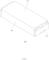
- FIG. 2 is a perspective view of the battery module according to an embodiment of the present invention
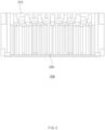
- FIG. 3 is an exploded perspective view of the battery module according to an embodiment of the present invention.
- the description of the foregoing embodiment may be equally or similarly applied to this embodiment.
- the battery module 100 may include a plurality of batteries 2. Each of the plurality of batteries 2 may be a secondary battery.
- the battery module 100 may include plates.
- the outside of the battery module 100 may be provided as the plates.
- the periphery of the battery module 100 may be defined by a lower plate 110, an upper plate 111, and an end plate 112.
- the lower plate 110, the upper plate 111, and the end plate 112 may be disposed in a shape surrounding the plurality of batteries 2.
- the lower plate 110 may be provided as a U-shaped plate.
- the upper plate 111 may be mounted on the lower plate 110 as a flat plate, and sides of the electrode leads 11 of the plurality of batteries 2 may be covered by the end plate 112.
- this is one example and is not particularly limited.
- a battery module 100 may include a bus bar frame 210.
- the bus bar frame 210 may be disposed between the plurality of batteries 2 and the end plate 112.
- the battery module 100 may include a buffer member 220.
- the buffer member 220 may be disposed between the plurality of batteries 2 and the bus bar frame 210.
- the buffer member 220 may disperse a pressure when one of the plurality of batteries 2 is swelled.
- the bus bar frame 210 and the end plate 112 may constitute a bus bar frame assembly 200.
- the battery module 100 may include a plurality of bus bar frame assemblies 200.
- the plurality of bus bar frame assemblies 200 are provided in the battery module 100 to cover both sides of the plurality of batteries 2.
- the bus bar frame assemblies 200 may cover sides of the electrode leads 11 of the plurality of batteries 2.
- FIG. 4 is an exploded perspective view of the bus bar frame assembly according to an embodiment of the present invention
- FIG. 5 is a side view of the bus bar frame assembly according to an embodiment of the present invention.
- the description of the foregoing embodiment may be equally or similarly applied to this embodiment.
- a bus bar 211 may be mounted on the bus bar frame 210.
- a connector may be mounted.
- the bus bar 211 or connector may be mounted on the bus bar frame 210 and electrically connected to the plurality of batteries 2.
- the buffer member 220 may extend in a predetermined direction.
- the buffer member 220 may extend in a direction perpendicular to a stacking direction of the plurality of batteries 2.
- the buffer member 220 may extend along the sealing part 13 disposed at one edge of each of the plurality of batteries 2.
- An extending length of the buffer member 220 may correspond to a length of a sealing part 130, but is not limited thereto.
- the bus bar frame 210 and the buffer member 220 may be integrated with each other.
- the battery module 100 may include a plurality of buffer members 220.
- the plurality of buffer members 220 may be arranged in a direction parallel to the direction in which the plurality of batteries 2 are stacked.
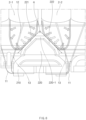
- FIG. 6 is a plan view illustrating a configuration of the buffer member when viewed from the top according to an embodiment of the present invention
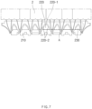
- FIG. 7 is a plan view illustrating an arrangement of the buffer members according to an embodiment of the present invention.
- the description of the foregoing embodiment may be equally or similarly applied to this embodiment.
- the battery module 100 may include the bus bar frame 210 which covers at least one side of the plurality of batteries 2 and on which the bus bar 211 electrically connecting the plurality of batteries 2 to the outside is mounted.
- the buffer member 220 may protrude toward the plurality of batteries 2 from an inner surface of the bus bar frame 210.
- the buffer member 220 may include a distal end 220-1.
- the distal end 220-1 may be disposed closest to the plurality of batteries 2 with respect to the protruding direction of the buffer member 220.
- the buffer member 220 may include support surfaces 220-2.
- the support surfaces 220-2 may include a first support surface 221 and a second support surface 222.
- the support surfaces 220-2 may have an obtuse angle with respect to the distal end 220-1 so as to face each of the plurality of batteries 2 adjacent to the buffer member 220.
- the first support surface 221 and the second support surface 222 may have an obtuse angle ⁇ therebetween.
- the support surfaces 220-2 may provide surfaces facing the plurality of batteries 2, and thus, pressure dispersion due to the supporting of the support surfaces when the batteries are swelled may be effectively achieved.
- Each of the support surfaces 220-2 may be a flat surface.
- each of the first support surface 221 and the second support surface 222 may be a flat surface.
- the present invention is not limited thereto.
- a direction in which the one battery presses one of the support surfaces 220-2 may cross a width direction of the one support surface.
- a direction in which one battery (e.g., first battery 2-1) presses the first support surface 221 may cross the width direction of the first support surface 221.
- a direction in which the other battery (e.g., second battery 2-2) presses the second support surface 222 may cross the width direction of the second support surface 222.
- the width direction of the support surfaces crosses the pressing direction of the batteries, the pressure dispersion when the batteries are swelled may be effectively achieved.
- the support surfaces 220-2 may cover 50% or more of an outer surface of the buffer member 220. In other words, the support surfaces 220-2 may occupy the largest area on the outer surfaces of the buffer member 220. As an area of the support surfaces 220-2 is wide, a pressure concentrated at the edge (e.g., the terrace part 12) during the swelling of the plurality of batteries 2 may be effectively dispersed.
- the buffer member 220 may be provided in plurality.
- the plurality of buffer members 220 may be disposed in the stacking direction of the plurality of batteries 2.
- an asymmetric buffer member 230 may be provided.
- two of the adjacent batteries may be defined as a first battery and a second battery, and also, a surface of the support surfaces, which faces the first battery, is defined as the first support surface, and a surface of the support surfaces, which faces the second battery, is defined as the second support surface
- the asymmetric buffer member 230 may have the first support surface and the second support surface, which have areas different from each other.
- a section A in which an angle between the support surfaces varies may be defined in the arrangement direction of the plurality of buffer members.
- the plurality of buffer members 220 may be disposed in the stacking direction of the plurality of batteries 2, and the section A in which the angle between the support surfaces 220-2 varies in the arrangement direction may be defined.
- a difference in area between the first support surface and the second support surface may increase toward the battery, which is stacked at the outermost side, of the plurality of batteries 2.
- an effect of the pressure dispersion may be adaptively maintained according to structural characteristics of the bus bar frame 210 and the plurality of batteries 2.
- FIG. 8 is a plan view illustrating contact of the secondary battery according to an embodiment of the present invention
- FIG. 9 is a partial perspective view of a contact area according to an embodiment of the present invention. The description of the foregoing embodiment may be equally or similarly applied to this embodiment.
- each of the plurality of batteries 2 may include a terrace part 12 provided with a sealing part 13 disposed on a distal end thereof.
- the buffer member 220 may be in contact with a predetermined area range of the terrace part 12.
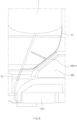
- an area that is in contact with the buffer member 220 on the area of the terrace part 12 excluding the sealing part 13 may be within a range of 25% to 55%.
- the support surfaces 220-2 of the buffer member 220 may be in contact with the terrace part 12 within a range of 25% to 55% of the area of the terrace part 12 excluding the sealing part 13 to support the terrace part 12, thereby effectively disperse the pressure concentrated at the edge of the secondary battery 1.
- the pressure concentrated at the edge of the secondary battery 1 may be dispersed through the support surfaces of the buffer member, and thus, the secondary battery 1 or the bus bar frame 210 may be prevented from being damaged to improve the structural stability.
Landscapes
- Chemical & Material Sciences (AREA)
- Chemical Kinetics & Catalysis (AREA)
- Electrochemistry (AREA)
- General Chemical & Material Sciences (AREA)
- Connection Of Batteries Or Terminals (AREA)
- Battery Mounting, Suspending (AREA)
- Sealing Battery Cases Or Jackets (AREA)
Applications Claiming Priority (3)
| Application Number | Priority Date | Filing Date | Title |
|---|---|---|---|
| KR20220070387 | 2022-06-09 | ||
| KR1020230047728A KR20230169837A (ko) | 2022-06-09 | 2023-04-11 | 버스바 프레임 어셈블리 및 이를 포함하는 전지모듈 |
| PCT/KR2023/006437 WO2023239066A1 (ko) | 2022-06-09 | 2023-05-11 | 버스바 프레임 어셈블리 및 이를 포함하는 전지모듈 |
Publications (2)
| Publication Number | Publication Date |
|---|---|
| EP4459763A1 true EP4459763A1 (de) | 2024-11-06 |
| EP4459763A4 EP4459763A4 (de) | 2025-05-07 |
Family
ID=89118619
Family Applications (1)
| Application Number | Title | Priority Date | Filing Date |
|---|---|---|---|
| EP23820002.6A Pending EP4459763A4 (de) | 2022-06-09 | 2023-05-11 | Sammelschienenrahmenanordnung und batteriemodul damit |
Country Status (4)
| Country | Link |
|---|---|
| US (1) | US20250202007A1 (de) |
| EP (1) | EP4459763A4 (de) |
| JP (1) | JP2025504212A (de) |
| WO (1) | WO2023239066A1 (de) |
Family Cites Families (12)
| Publication number | Priority date | Publication date | Assignee | Title |
|---|---|---|---|---|
| US8609276B2 (en) * | 2011-06-23 | 2013-12-17 | Samsung Sdi Co., Ltd. | Battery pack |
| KR102157377B1 (ko) * | 2017-05-25 | 2020-09-17 | 주식회사 엘지화학 | 배터리 모듈, 이를 포함하는 배터리 팩 및 배터리 모듈 생산 방법 |
| US10601003B2 (en) * | 2017-10-30 | 2020-03-24 | Lg Chem, Ltd. | Battery module and method of assembling the battery module |
| KR20190126608A (ko) * | 2018-05-02 | 2019-11-12 | 에스케이이노베이션 주식회사 | 배터리 모듈 |
| KR102395228B1 (ko) * | 2018-10-10 | 2022-05-04 | 주식회사 엘지에너지솔루션 | 버스바 프레임 조립 방법 |
| KR102722680B1 (ko) * | 2018-11-26 | 2024-10-25 | 주식회사 엘지에너지솔루션 | 전지 모듈 및 그 제조 방법 |
| KR102366138B1 (ko) * | 2018-12-06 | 2022-02-22 | 주식회사 엘지에너지솔루션 | 전지 모듈 |
| CN209822772U (zh) * | 2019-06-28 | 2019-12-20 | 宁德时代新能源科技股份有限公司 | 电池模组 |
| KR102935639B1 (ko) * | 2020-10-06 | 2026-03-05 | 주식회사 엘지에너지솔루션 | 배터리 모듈, 이를 포함하는 배터리 팩 및 자동차 |
| KR102941254B1 (ko) * | 2020-11-04 | 2026-03-18 | 주식회사 엘지에너지솔루션 | 전지 모듈 및 이를 포함하는 전지팩 |
| KR102690690B1 (ko) | 2021-10-01 | 2024-08-05 | 주식회사 골프존 | 골프 코스 리스트 제공 장치 및 골프 코스 리스트 제공 방법 |
| KR20220070387A (ko) | 2022-05-12 | 2022-05-31 | 정보헌 | 해양심층수를 활용한 미네랄 강화 기능성 계란의 제조방법 및 그에 의해 제조된 기능성 계란 |
-
2023
- 2023-05-11 EP EP23820002.6A patent/EP4459763A4/de active Pending
- 2023-05-11 US US18/835,228 patent/US20250202007A1/en active Pending
- 2023-05-11 JP JP2024547113A patent/JP2025504212A/ja active Pending
- 2023-05-11 WO PCT/KR2023/006437 patent/WO2023239066A1/ko not_active Ceased
Also Published As
| Publication number | Publication date |
|---|---|
| US20250202007A1 (en) | 2025-06-19 |
| WO2023239066A1 (ko) | 2023-12-14 |
| EP4459763A4 (de) | 2025-05-07 |
| JP2025504212A (ja) | 2025-02-06 |
Similar Documents
| Publication | Publication Date | Title |
|---|---|---|
| US8852789B2 (en) | Battery module having battery cell holder | |
| US8765290B2 (en) | Rechargeable battery with terminal junction and prong | |
| US9450219B2 (en) | Battery module | |
| US9203065B2 (en) | Battery module | |
| US8974952B2 (en) | Rechargeable battery | |
| US9040192B2 (en) | Lithium rechargeable battery | |
| EP2450990B1 (de) | Batteriemodul mit Batteriezellenhalter | |
| CN209786120U (zh) | 二次电池和电池模组 | |
| KR20010041600A (ko) | 다면적 셀 구조체 | |
| KR20100102542A (ko) | 이차 전지 | |
| CN105322210A (zh) | 可再充电电池 | |
| US20090226804A1 (en) | Package structure of electric storage cells | |
| US20230344053A1 (en) | Support structure | |
| EP4167372B1 (de) | Batteriemodul mit zickzackförmig angeordneten anschlussklemmen | |
| US8623535B2 (en) | Battery module | |
| EP4459763A1 (de) | Sammelschienenrahmenanordnung und batteriemodul damit | |
| KR20230169837A (ko) | 버스바 프레임 어셈블리 및 이를 포함하는 전지모듈 | |
| CN118786564A (zh) | 汇流条框架组件和包括该汇流条框架组件的电池模块 | |
| KR20080028091A (ko) | 이차 전지 | |
| EP4601069A1 (de) | Elektrodenanordnung und sekundärbatterie mit der elektrodenanordnung | |
| EP4685992A1 (de) | Schutzkoppler für elektrodenanordnung und sekundärbatterie damit | |
| US20260051605A1 (en) | Battery pack | |
| EP4358250A1 (de) | Batteriemodul | |
| KR20070071062A (ko) | 이차 전지 | |
| KR20250176921A (ko) | 배터리 모듈 |
Legal Events
| Date | Code | Title | Description |
|---|---|---|---|
| STAA | Information on the status of an ep patent application or granted ep patent |
Free format text: STATUS: THE INTERNATIONAL PUBLICATION HAS BEEN MADE |
|
| PUAI | Public reference made under article 153(3) epc to a published international application that has entered the european phase |
Free format text: ORIGINAL CODE: 0009012 |
|
| STAA | Information on the status of an ep patent application or granted ep patent |
Free format text: STATUS: REQUEST FOR EXAMINATION WAS MADE |
|
| 17P | Request for examination filed |
Effective date: 20240801 |
|
| AK | Designated contracting states |
Kind code of ref document: A1 Designated state(s): AL AT BE BG CH CY CZ DE DK EE ES FI FR GB GR HR HU IE IS IT LI LT LU LV MC ME MK MT NL NO PL PT RO RS SE SI SK SM TR |
|
| A4 | Supplementary search report drawn up and despatched |
Effective date: 20250404 |
|
| RIC1 | Information provided on ipc code assigned before grant |
Ipc: H01M 50/143 20210101ALI20250331BHEP Ipc: H01M 50/105 20210101ALI20250331BHEP Ipc: H01M 50/183 20210101ALI20250331BHEP Ipc: H01M 50/211 20210101ALI20250331BHEP Ipc: H01M 50/578 20210101ALI20250331BHEP Ipc: H01M 50/502 20210101ALI20250331BHEP Ipc: H01M 50/242 20210101AFI20250331BHEP |
|
| DAV | Request for validation of the european patent (deleted) | ||
| DAX | Request for extension of the european patent (deleted) | ||
| GRAP | Despatch of communication of intention to grant a patent |
Free format text: ORIGINAL CODE: EPIDOSNIGR1 |
|
| STAA | Information on the status of an ep patent application or granted ep patent |
Free format text: STATUS: GRANT OF PATENT IS INTENDED |
|
| INTG | Intention to grant announced |
Effective date: 20260331 |