EP4459812A1 - Doppelverriegelungssystem - Google Patents
Doppelverriegelungssystem Download PDFInfo
- Publication number
- EP4459812A1 EP4459812A1 EP24173635.4A EP24173635A EP4459812A1 EP 4459812 A1 EP4459812 A1 EP 4459812A1 EP 24173635 A EP24173635 A EP 24173635A EP 4459812 A1 EP4459812 A1 EP 4459812A1
- Authority
- EP
- European Patent Office
- Prior art keywords
- connector
- locking member
- counter
- safety locking
- cpa
- Prior art date
- Legal status (The legal status is an assumption and is not a legal conclusion. Google has not performed a legal analysis and makes no representation as to the accuracy of the status listed.)
- Pending
Links
Images




Classifications
-
- H—ELECTRICITY
- H01—ELECTRIC ELEMENTS
- H01R—ELECTRICALLY-CONDUCTIVE CONNECTIONS; STRUCTURAL ASSOCIATIONS OF A PLURALITY OF MUTUALLY-INSULATED ELECTRICAL CONNECTING ELEMENTS; COUPLING DEVICES; CURRENT COLLECTORS
- H01R13/00—Details of coupling devices of the kinds covered by groups H01R12/70 or H01R24/00 - H01R33/00
- H01R13/64—Means for preventing incorrect coupling
- H01R13/641—Means for preventing incorrect coupling by indicating incorrect coupling; by indicating correct or full engagement
-
- H—ELECTRICITY
- H01—ELECTRIC ELEMENTS
- H01R—ELECTRICALLY-CONDUCTIVE CONNECTIONS; STRUCTURAL ASSOCIATIONS OF A PLURALITY OF MUTUALLY-INSULATED ELECTRICAL CONNECTING ELEMENTS; COUPLING DEVICES; CURRENT COLLECTORS
- H01R13/00—Details of coupling devices of the kinds covered by groups H01R12/70 or H01R24/00 - H01R33/00
- H01R13/40—Securing contact members in or to a base or case; Insulating of contact members
- H01R13/42—Securing in a demountable manner
- H01R13/436—Securing a plurality of contact members by one locking piece or operation
- H01R13/4364—Insertion of locking piece from the front
- H01R13/4365—Insertion of locking piece from the front comprising a temporary and a final locking position
-
- H—ELECTRICITY
- H01—ELECTRIC ELEMENTS
- H01R—ELECTRICALLY-CONDUCTIVE CONNECTIONS; STRUCTURAL ASSOCIATIONS OF A PLURALITY OF MUTUALLY-INSULATED ELECTRICAL CONNECTING ELEMENTS; COUPLING DEVICES; CURRENT COLLECTORS
- H01R13/00—Details of coupling devices of the kinds covered by groups H01R12/70 or H01R24/00 - H01R33/00
- H01R13/62—Means for facilitating engagement or disengagement of coupling parts or for holding them in engagement
- H01R13/639—Additional means for holding or locking coupling parts together, after engagement, e.g. separate keylock, retainer strap
-
- H—ELECTRICITY
- H01—ELECTRIC ELEMENTS
- H01R—ELECTRICALLY-CONDUCTIVE CONNECTIONS; STRUCTURAL ASSOCIATIONS OF A PLURALITY OF MUTUALLY-INSULATED ELECTRICAL CONNECTING ELEMENTS; COUPLING DEVICES; CURRENT COLLECTORS
- H01R13/00—Details of coupling devices of the kinds covered by groups H01R12/70 or H01R24/00 - H01R33/00
- H01R13/46—Bases; Cases
- H01R13/502—Bases; Cases composed of different pieces
- H01R13/508—Bases; Cases composed of different pieces assembled by a separate clip or spring
-
- H—ELECTRICITY
- H01—ELECTRIC ELEMENTS
- H01R—ELECTRICALLY-CONDUCTIVE CONNECTIONS; STRUCTURAL ASSOCIATIONS OF A PLURALITY OF MUTUALLY-INSULATED ELECTRICAL CONNECTING ELEMENTS; COUPLING DEVICES; CURRENT COLLECTORS
- H01R13/00—Details of coupling devices of the kinds covered by groups H01R12/70 or H01R24/00 - H01R33/00
- H01R13/46—Bases; Cases
- H01R13/516—Means for holding or embracing insulating body, e.g. casing, hoods
-
- H—ELECTRICITY
- H01—ELECTRIC ELEMENTS
- H01R—ELECTRICALLY-CONDUCTIVE CONNECTIONS; STRUCTURAL ASSOCIATIONS OF A PLURALITY OF MUTUALLY-INSULATED ELECTRICAL CONNECTING ELEMENTS; COUPLING DEVICES; CURRENT COLLECTORS
- H01R13/00—Details of coupling devices of the kinds covered by groups H01R12/70 or H01R24/00 - H01R33/00
- H01R13/62—Means for facilitating engagement or disengagement of coupling parts or for holding them in engagement
- H01R13/629—Additional means for facilitating engagement or disengagement of coupling parts, e.g. aligning or guiding means, levers, gas pressure electrical locking indicators, manufacturing tolerances
- H01R13/631—Additional means for facilitating engagement or disengagement of coupling parts, e.g. aligning or guiding means, levers, gas pressure electrical locking indicators, manufacturing tolerances for engagement only
-
- H—ELECTRICITY
- H01—ELECTRIC ELEMENTS
- H01R—ELECTRICALLY-CONDUCTIVE CONNECTIONS; STRUCTURAL ASSOCIATIONS OF A PLURALITY OF MUTUALLY-INSULATED ELECTRICAL CONNECTING ELEMENTS; COUPLING DEVICES; CURRENT COLLECTORS
- H01R43/00—Apparatus or processes specially adapted for manufacturing, assembling, maintaining, or repairing of line connectors or current collectors or for joining electric conductors
- H01R43/26—Apparatus or processes specially adapted for manufacturing, assembling, maintaining, or repairing of line connectors or current collectors or for joining electric conductors for engaging or disengaging the two parts of a coupling device
-
- H—ELECTRICITY
- H01—ELECTRIC ELEMENTS
- H01R—ELECTRICALLY-CONDUCTIVE CONNECTIONS; STRUCTURAL ASSOCIATIONS OF A PLURALITY OF MUTUALLY-INSULATED ELECTRICAL CONNECTING ELEMENTS; COUPLING DEVICES; CURRENT COLLECTORS
- H01R13/00—Details of coupling devices of the kinds covered by groups H01R12/70 or H01R24/00 - H01R33/00
- H01R13/62—Means for facilitating engagement or disengagement of coupling parts or for holding them in engagement
- H01R13/627—Snap or like fastening
- H01R13/6271—Latching means integral with the housing
- H01R13/6272—Latching means integral with the housing comprising a single latching arm
Definitions
- the present disclosure in general relates to establishing a secured locking between a connector position assurance (CPA) device and a connector assembly. More particularly, the disclosure relates to a safety lock mechanism having Dual Lock System (DLS) to prevent opening of CPA device for a connector of the connector assembly.
- CPA connector position assurance
- DLS Dual Lock System
- the connector assembly generally comprises a male connector and a female connector.
- male or “female” connectors refers, for example, to the kind of terminals, respectively male or female, accommodated in these respective types of connectors.
- a female cable connector is mated with a male cable connector.
- the connector and counter-connector can be of any type (plug, socket, etc.).
- the CPA function is introduced to the female connector by installing the CPA device therein or thereon.
- a terminal position assurance (TPA) device can also be introduced into the female connector to ensure a secure connection of electrical terminals.
- an improved connector assembly comprising a connector and a counter-connector configured to be mated in a mating direction.
- the connector comprises a connector housing, at least one terminal, configured to be inserted in a cavity formed in the connector housing, and a CPA device slidably mounted on the connector housing between an initial position and a final position. The movement of the CPA device between the initial position and the final position is released by the mating of the connector with the counter-connector.
- the connector further comprises a safety locking member which is slidably mounted on the connector between an open position in which the safety locking member is attached to the connector and in which the safety locking member leaves both the CPA device and the counter-connector free to be moved with respect to the connector and a closed position in which the safety locking member prevents a movement of both the CPA device and the counter-connector with respect to the connector.
- the present disclosure relates to a connector assembly in which not only is the CPA device prevented from being inadvertently opened and/or detached, but the connector assembly is provided with a system which robustly reinforces the maintenance of the connection between the connector and the counter-connector.
- this connector assembly possibly comprises one or more of the following features, each one of these features being considered independently of each other or in combination of one or several others.
- orientations and the adverbs such as above, below, etc. refer to the respective orientations of the connector parts shown in the Figures. The skill person will understand that a change in these orientations will lead to a change in the meaning of these adverbs.
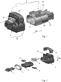
- the connector assembly 1 comprises a connector 2 (e.g., a female connector) and a counter-connector 3 (e.g., a male connector) - See Figure 1 .
- the connector 2 and the counter-connector 3 are mated along a mating direction AD.
- the connector 2 comprises a housing 50.
- the housing 50 comprises two parts: an outer housing 4, an inner housing 5.
- the connector 2 further comprises an interfacial seal 6 and electrical terminals 7 (see Figure 2 ). Each terminal 7 is accommodated in a respective cavity formed in the housing 50 (this cavity being cavity formed in inner housing 5, in the illustrated example).
- the outer housing 4 and inner housing 5 are made of molded plastic (a dielectric material).
- the interfacial seal 6 is made of elastomeric material.
- the terminals 7 are female terminals made by stamping, bending, folding and possibly plating a sheet of metal (e.g. copper or a copper alloy).
- these female terminals 7 are of the type marketed under the name "0.63 MQS" (MQS stands for Micro Quadlock System).
- the connector 2 is a 6-way MQS female connector.
- the counter-connector 3 has a male housing 25 made of molded plastic.
- the male housing 25 comprises a pair of SLS activation features 26, a pair of counter-connector locking latches 27, a CPA activating feature 28 and a CPA protecting feature 29.
- the connector 2 is further provided with a CPA device 8, a pair of TPA devices 9 and a safety locking member 10, all made of molded plastic.
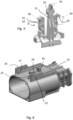
- the safety locking member 10 comprises two pairs of SLS locking latches 11, a pair of SLS pre-lock latches 12, a pair of SLS activation latches 13 and a pair of CPA locking features 14 (see Figures 3 and 4 ).
- the safety locking member 10 is mounted on the connector 2 in a mounting direction MD, parallel to a plane essentially perpendicular to the mating direction AD (see Figure 2 ). More particularly, the safety locking member 10 is mounted on the outer housing 4.
- the safety locking member 10 has a general U-shape, with two legs 15 extending essentially parallel to the mounting direction MD and a beam 16 extending essentially perpendicular to the mounting direction MD (see Figures 3 and 4 ).
- Each SLS locking latch 11 comprises a hook 17 outwardly extending from a flexible arm 18 (see Figure 4 ). Each hook 17 engages a slot 19 provided on the outer housing 4 (see Figures 1 and 2 ).
- the safety locking member 10 is configured to be slidably mounted on the outer housing 4 between an open position and a closed position (while the hooks 17 are kept in the slots 19 and move along the slots 19). However, when mounted and placed in open position on the outer housing 4, the safety locking member 10 is prevented by the SLS pre-lock latches 12, from being further inserted in the outer housing 4 toward the closed position. More particularly, the SLS pre-lock latches 12 consist of protrusions having blocking surfaces perpendicular to the mounting direction MD, these blocking surfaces engaging the outer housing 4.
- the SLS activation latches 13 are configured to release the SLS pre-lock latches 12 from their engagement with the outer housing 4, when the counter-connector 3 is mated with the connector 2.
- each SLS activation latch 13 is supported by a same branch 20 (extending essentially parallel to the mounting direction MD) as a SLS pre-lock latch 12 (See Figure 4 ), and each SLS activation latch 13 comprises a slanted surface 21 configured to slide over a respective SLS activation feature 26 of the counter-connector 3 during the assembly of the connector 2 and counter-connector 3.
- the counter-connector 3 comprises beveled surfaces 22 (See Figure 6 ), on the SLS activation features 26, configured to slide over the slanted surfaces 21 to help the branches 20 to spread apart.
- each SLS activation latch 13 springs back in a notch 23 (See Figure 6 ) and each SLS pre-lock latch 12 springs back in a recess 24 (See Figure 16 ).
- Each CPA locking feature 14 has a general pillar shape extending, from an inner surface of the beam 16 of the safety locking member 10, essentially parallel to the mounting direction MD (See Figure 4 ).
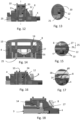
- the CPA device 8 is stopped in initial (or pre-lock) position by a stop 30 located on the outer housing 4 (See Figures 7 and 8 ). More particularly, the CPA device 8 comprises a locking lance 31 with a blocking surface 32 on either side of the locking lance 31, engaging first stop surfaces 35 located on the outer housing 4, so as to prevent the CPA device 8 from being moved frontwards, when the CPA device 8 is in its initial position and when the connector 2 is not mated with the counter-connector 3.
- the locking lance 31 also comprises an activation surface 33 at its free end.
- the CPA device 8 comprises locking features 34 engaging second stop surfaces 36 located on the outer housing 4, so as to prevent the CPA device 8 from being moved backwards (and removed from the connector 2) when the CPA device 8 is in its initial position (See Figure 8 ).
- said activation surface 33 is moved upwards by the CPA activation feature 28 (e.g., in the shape of a protrusion) located on the upper face of the male housing 25, so as to bend the locking lance 31 and to release the blocking surfaces 32 from the first second stop surfaces 35 of the outer housing 4 (See Figure 9 ).
- the CPA device 8 is released from the first stop surfaces 35 and can be pushed further towards the mating face of the connector 2, up to its final position (See Figures 10 and 11 ).
- a connector latch 37 (integral with the outer housing 104) engages the protrusion forming the CPA activation feature 28.
- the connector latch 37 and the CPA activation feature 28 then provide a primary locking function of the connectors.
- the CPA device 8 can be pushed and moved to its final position.
- the CPA device 8 prevents the connector latch 37 from being bent upwards.
- the CPA device 8 has CPA blocking branches 38 inserted (when the CPA device 8 is in final position) between an outer housing portion 39 and the connector latch 37, thereby ensuring a secondary locking function (See Figure 10 ).
- each blocking branch 38 has a blocking notch 40 (See Figure 5 ).
- Each blocking notch 40 is open outward and has a front stop 41 and a rear stop 42.
- each CPA locking feature 14 can engage the front stop 41 and a rear stop 42 so as to prevent the CPA device 8 from being moved frontwards or backwards.
- the CPA locking features 14 of the safety locking member 10 also cooperates with the counter-connector locking latches 27 of the counter-connector 3 (See Figure 18 ). This prevents the connector 2 and counter-connector 3 from being inadvertently unmated and disconnected.
- the connector assembly 101 comprises a connector 102 (e.g., a female connector) and a counter-connector 103 (e.g., a male connector) - See Figure 19 .
- the connector 102 and the counter-connector 103 are mated along a mating direction AD.
- the connector 102 comprises a housing 150.
- the housing 150 comprises two parts: an outer housing 104, an inner housing 105.
- the connector 102 further comprises an interfacial seal 106 and electrical terminals 107 (see Figure 20 ). Each terminal 107 is accommodated in a respective cavity formed in the housing 150 (this cavity being formed in inner housing 105, in the illustrated example).
- the outer housing 104 and inner housing 105 are made of molded plastic (a dielectric material).
- the interfacial seal 106 is made of elastomeric material.
- the terminals 107 are female terminals made by stamping, bending, folding and possibly plating a sheet of metal (e.g. copper or a copper alloy).
- these female terminals 107 are of the type marketed under the name "0.63 MQS" (MQS stands for Micro Quadlock System).
- the connector 102 is a 6-way MQS female connector.
- the counter-connector 103 has a male housing 125 made of molded plastic.
- the male housing 125 comprises a pair of SLS activation features 126, a pair of counter-connector locking latches 127, a CPA activating feature 128 and a CPA protecting feature 129.
- the connector 102 is further provided with a CPA device 108, a pair of TPA devices 109 and a safety locking member 110, all made of molded plastic.
- the safety locking member 110 comprises on pair of SLS locking latches 111, a pair of SLS pre-lock latches 112, a pair of SLS activation latches 113, a pair of CPAlocking features 114 and a pair of counter-connector locking features 143 (see Figures 21 and 22 ).
- the safety locking member 110 is mounted on the connector 102 in a mounting direction MD, parallel to a plane essentially perpendicular to the mating direction AD (see Figure 20 ). More particularly, the safety locking member 110 is mounted on the outer housing 104.
- the safety locking member 110 has a general U-shape, with two legs 115 extending essentially parallel to the mounting direction MD and a beam 116 extending essentially perpendicular to the mounting direction MD.
- the safety locking member 110 is kept on the outer housing 104 thanks to the SLS locking latches 111.
- Each SLS locking latch 111 comprises a hook 117 outwardly extending from a flexible arm 118. Each hook 117 engages a slot 119 provided on the outer housing 104 (see Figures 19 and 20 ).
- the safety locking member 110 is configured to be slidably mounted on the outer housing 104 between an open position and a closed position (while the hooks 117 are retained in the slots 119 and move along the slots 119).
- the safety locking member 110 is prevented by the SLS pre-lock latches 112, from being further inserted in the outer housing 104 toward the closed position.
- the SLS pre-lock latches 112 consist of protrusions having blocking surfaces perpendicular to the mounting direction MD, these blocking surfaces engaging the outer housing 104.
- the SLS activation latches 113 are configured to release the SLS pre-lock latches 112 from their engagement with the outer housing 104, when the counter-connector 103 is mated with the connector 102.
- each SLS activation latch 113 consists in a branch 120 (extending essentially parallel to the mounting direction MD) supporting a SLS pre-lock latch 112 (See Figure 21 ).
- Each SLS activation latch 113 is configured to slide over a respective SLS activation feature 126 of the counter-connector 103 during the assembly of the connector 102 and counter-connector 103.
- the counter-connector 103 comprises beveled surfaces 122 ( Figure 24 ), on the SLS activation features 126, to help the branches 120 to spread apart.
- Each CPA locking feature 114 has a general pillar shape extending, from an inner surface of the beam 116 of the safety locking member 110, essentially parallel to the mounting direction MD (See Figure 22 ).
- the CPA device 108 is stopped in initial (or pre-lock) position by a stop 130 located on the outer housing 104 (See Figures 25 and 26 ). More particularly, the CPA device 108 comprises a locking lance 131 with a blocking surface 132 on either side of the locking lance 131, engaging first stop surfaces 135 located on the outer housing 104, so as to prevent the CPA device 108 from being moved frontwards, when the CPA device 108 is in its initial position and when the connector 102 is not mated with the counter-connector 103.
- the locking lance 131 also comprises an activation surface 133 at its free end.
- the CPA device 108 comprises locking features 134 engaging second stop surfaces 136 located on the outer housing 104, so as to prevent the CPA device 108 from being moved backwards (and removed from the connector 102) when the CPA device 108 is in its initial position (See Figure 26 ).
- said activation surface 133 is moved upwards by the CPA activation feature 128 (e.g., in the shape of a protrusion) located on the upper face of the male housing 125, so as to bend the locking lance 131 and to release the blocking surfaces 132 from the first second stop surfaces 135 of the outer housing 104 (See Figure 27 ).
- the CPA device 108 is released from the first stop surfaces 135 and can be pushed further towards the mating face of the connector 102, up to its final position (See Figures 28 and 29 ).
- a connector latch 137 (integral with the outer housing 104) engages the protrusion forming the CPA activation feature 128.
- the connector latch 137 and the CPA activation feature 128 then provide a primary locking function of the connectors.
- the CPA device 108 can be pushed and moved to its final position.
- the CPA device 108 In the final position of the CPA device 108, the CPA device 108 prevents the connector latch 137 from being bent upwards.
- the CPA device 108 has CPA blocking branches 138 inserted (when the CPA device 108 is in final position) between an outer housing portion 139 and the connector latch 137, thereby ensuring a secondary locking function (See Figure 28 ).
- each blocking branch 138 has a blocking notch 140 (See Figure 23 ).
- Each blocking notch 140 is open outward and has a front stop 141 and a rear stop 142.
- the counter-connector locking features 143 of the safety locking member 110 also cooperates with the counter-connector locking latches 127 of the counter-connector 103 (See Figures 33 and 34 ). This prevents the connector 102 and counter-connector 103 from being inadvertently unmated and disconnected.
- the number of SLS locking latches 11, 111, of SLS pre-lock latches 12, 112, of SLS activation latches 13, 113, of CPA locking features 14, of counter-connector locking features 143, etc. may vary.
- the respective shapes of the various elements forming the connector 2, 102 and counter-connector 3, 103 may also vary.
Landscapes
- Engineering & Computer Science (AREA)
- Manufacturing & Machinery (AREA)
- Details Of Connecting Devices For Male And Female Coupling (AREA)
Applications Claiming Priority (1)
| Application Number | Priority Date | Filing Date | Title |
|---|---|---|---|
| IN202341030990 | 2023-05-01 |
Publications (1)
| Publication Number | Publication Date |
|---|---|
| EP4459812A1 true EP4459812A1 (de) | 2024-11-06 |
Family
ID=90970768
Family Applications (1)
| Application Number | Title | Priority Date | Filing Date |
|---|---|---|---|
| EP24173635.4A Pending EP4459812A1 (de) | 2023-05-01 | 2024-05-01 | Doppelverriegelungssystem |
Country Status (3)
| Country | Link |
|---|---|
| US (1) | US20240372289A1 (de) |
| EP (1) | EP4459812A1 (de) |
| CN (1) | CN118889123A (de) |
Citations (2)
| Publication number | Priority date | Publication date | Assignee | Title |
|---|---|---|---|---|
| DE102021127033B3 (de) * | 2021-10-19 | 2022-11-10 | Md Elektronik Gmbh | Steckverbinderanordnung zum verbinden von signalleitern |
| CN115336116A (zh) * | 2020-04-10 | 2022-11-11 | 住友电装株式会社 | 连接器单元、线束以及连接器嵌合结构 |
-
2024
- 2024-05-01 EP EP24173635.4A patent/EP4459812A1/de active Pending
- 2024-05-01 US US18/652,100 patent/US20240372289A1/en active Pending
- 2024-05-06 CN CN202410548091.6A patent/CN118889123A/zh active Pending
Patent Citations (2)
| Publication number | Priority date | Publication date | Assignee | Title |
|---|---|---|---|---|
| CN115336116A (zh) * | 2020-04-10 | 2022-11-11 | 住友电装株式会社 | 连接器单元、线束以及连接器嵌合结构 |
| DE102021127033B3 (de) * | 2021-10-19 | 2022-11-10 | Md Elektronik Gmbh | Steckverbinderanordnung zum verbinden von signalleitern |
Also Published As
| Publication number | Publication date |
|---|---|
| CN118889123A (zh) | 2024-11-01 |
| US20240372289A1 (en) | 2024-11-07 |
Similar Documents
| Publication | Publication Date | Title |
|---|---|---|
| JP4267935B2 (ja) | 電気コネクタ組立体及び電気コネクタ | |
| US6824406B1 (en) | Electrical connector assembly | |
| JP4405164B2 (ja) | 電気コネクタ組立体及び電気コネクタ半体組立体 | |
| US6244880B1 (en) | Low-insertion force connector | |
| EP1672747B1 (de) | Verbinder | |
| US20090186523A1 (en) | Electrical connector | |
| US9409536B2 (en) | Connector assembly with automatic secondary lock | |
| KR20180117548A (ko) | 레버를 갖는 전기 커넥터 | |
| CN110571567B (zh) | 分阶段释放的电连接器组件 | |
| EP3769377B1 (de) | Verbinderpositionsicherungselement | |
| US12021326B2 (en) | Connector having a movable member | |
| US6149473A (en) | Connector with secondary locking and coupling mechanism | |
| EP1315249A2 (de) | Stellungssicherheitseinrichtung für Verbinder, Verfahren und Vorrichtngen für die Herstellung | |
| EP0713263B1 (de) | Selbstverriegelnde Kontaktstruktur | |
| US6623286B2 (en) | Lever-type connector | |
| CN111834788B (zh) | 带有端子锁的电端子壳体 | |
| EP4459804A1 (de) | Verbinderanordnung mit einer in ein cpa-element integrierten tpa-funktion | |
| EP4459812A1 (de) | Doppelverriegelungssystem | |
| KR102722218B1 (ko) | 커넥터 위치 보장 부재 | |
| CN115441225A (zh) | 具有连接器位置保证件和机械辅助件的电连接器 | |
| JPH09283221A (ja) | 半嵌合防止コネクタ | |
| EP4697524A1 (de) | Elektrischer verbindungsstecker und seine montageverfahren | |
| EP4641847A1 (de) | Anordnung mit cpa und verbinderanordnung |
Legal Events
| Date | Code | Title | Description |
|---|---|---|---|
| PUAI | Public reference made under article 153(3) epc to a published international application that has entered the european phase |
Free format text: ORIGINAL CODE: 0009012 |
|
| STAA | Information on the status of an ep patent application or granted ep patent |
Free format text: STATUS: THE APPLICATION HAS BEEN PUBLISHED |
|
| AK | Designated contracting states |
Kind code of ref document: A1 Designated state(s): AL AT BE BG CH CY CZ DE DK EE ES FI FR GB GR HR HU IE IS IT LI LT LU LV MC ME MK MT NL NO PL PT RO RS SE SI SK SM TR |
|
| STAA | Information on the status of an ep patent application or granted ep patent |
Free format text: STATUS: REQUEST FOR EXAMINATION WAS MADE |
|
| 17P | Request for examination filed |
Effective date: 20250505 |