EP4459843A1 - Paquet de tôles fixable de manière solidaire en rotation sur un arbre ainsi qu'une machine électrique dotée d'un tel paquet de tôles - Google Patents
Paquet de tôles fixable de manière solidaire en rotation sur un arbre ainsi qu'une machine électrique dotée d'un tel paquet de tôles Download PDFInfo
- Publication number
- EP4459843A1 EP4459843A1 EP24169490.0A EP24169490A EP4459843A1 EP 4459843 A1 EP4459843 A1 EP 4459843A1 EP 24169490 A EP24169490 A EP 24169490A EP 4459843 A1 EP4459843 A1 EP 4459843A1
- Authority
- EP
- European Patent Office
- Prior art keywords
- lamella
- shaft
- bend
- disc
- angle
- Prior art date
- Legal status (The legal status is an assumption and is not a legal conclusion. Google has not performed a legal analysis and makes no representation as to the accuracy of the status listed.)
- Pending
Links
Images


Classifications
-
- H—ELECTRICITY
- H02—GENERATION; CONVERSION OR DISTRIBUTION OF ELECTRIC POWER
- H02K—DYNAMO-ELECTRIC MACHINES
- H02K1/00—Details of the magnetic circuit
- H02K1/06—Details of the magnetic circuit characterised by the shape, form or construction
- H02K1/22—Rotating parts of the magnetic circuit
- H02K1/27—Rotor cores with permanent magnets
- H02K1/2706—Inner rotors
- H02K1/272—Inner rotors the magnetisation axis of the magnets being perpendicular to the rotor axis
- H02K1/274—Inner rotors the magnetisation axis of the magnets being perpendicular to the rotor axis the rotor consisting of two or more circumferentially positioned magnets
- H02K1/2753—Inner rotors the magnetisation axis of the magnets being perpendicular to the rotor axis the rotor consisting of two or more circumferentially positioned magnets the rotor consisting of magnets or groups of magnets arranged with alternating polarity
- H02K1/276—Magnets embedded in the magnetic core, e.g. interior permanent magnets [IPM]
- H02K1/2766—Magnets embedded in the magnetic core, e.g. interior permanent magnets [IPM] having a flux concentration effect
-
- H—ELECTRICITY
- H02—GENERATION; CONVERSION OR DISTRIBUTION OF ELECTRIC POWER
- H02K—DYNAMO-ELECTRIC MACHINES
- H02K1/00—Details of the magnetic circuit
- H02K1/06—Details of the magnetic circuit characterised by the shape, form or construction
- H02K1/22—Rotating parts of the magnetic circuit
-
- H—ELECTRICITY
- H02—GENERATION; CONVERSION OR DISTRIBUTION OF ELECTRIC POWER
- H02K—DYNAMO-ELECTRIC MACHINES
- H02K1/00—Details of the magnetic circuit
- H02K1/06—Details of the magnetic circuit characterised by the shape, form or construction
- H02K1/12—Stationary parts of the magnetic circuit
-
- H—ELECTRICITY
- H02—GENERATION; CONVERSION OR DISTRIBUTION OF ELECTRIC POWER
- H02K—DYNAMO-ELECTRIC MACHINES
- H02K1/00—Details of the magnetic circuit
- H02K1/06—Details of the magnetic circuit characterised by the shape, form or construction
- H02K1/22—Rotating parts of the magnetic circuit
- H02K1/28—Means for mounting or fastening rotating magnetic parts on to, or to, the rotor structures
-
- H—ELECTRICITY
- H02—GENERATION; CONVERSION OR DISTRIBUTION OF ELECTRIC POWER
- H02K—DYNAMO-ELECTRIC MACHINES
- H02K7/00—Arrangements for handling mechanical energy structurally associated with dynamo-electric machines, e.g. structural association with mechanical driving motors or auxiliary dynamo-electric machines
- H02K7/003—Couplings; Details of shafts
-
- H—ELECTRICITY
- H02—GENERATION; CONVERSION OR DISTRIBUTION OF ELECTRIC POWER
- H02K—DYNAMO-ELECTRIC MACHINES
- H02K2213/00—Specific aspects, not otherwise provided for and not covered by codes H02K2201/00 - H02K2211/00
- H02K2213/03—Machines characterised by numerical values, ranges, mathematical expressions or similar information
Definitions
- the invention relates to a lamination pack intended for an electrical machine and which can be fixed in a rotationally fixed manner on a shaft or an axle of the electrical machine, with a plurality of plane-parallel laminations which lie flat against one another and each have a particularly ring-shaped closed opening for the shaft or axle, wherein several laminations have at least one inward-facing formation for the positive and non-positive fixing of the lamination pack in at least one groove-shaped recess in the shaft or axle delimited by lateral inner wall surfaces, wherein several formations together form at least one lamination wedge and at least some of the formations have at least one side surface with a bend and/or angle in the circumferential direction, which forms an obtuse angle with a main extension plane of the lamination having the formation, wherein the side surface has a contact surface for contacting the inner wall surface and for non-positive and positive fixing in the recess, wherein in the lamination pack each lamination has a bend or the formation having an angle is followed by at least one further lam
- rotors which usually have a rotor shaft on which several laminations are fixed in a rotationally fixed manner as a lamination package in order to reduce power losses due to electrical eddy currents.
- a lamella wedge spring geometry of a lamella pack for a rotor is known, which is loaded with an excess to a groove width and has a symmetrical and asymmetrical slot groove in a lamella wedge to reduce bending stiffness, whereby when the lamella wedge of the lamella pack is inserted into a shaft groove, the lamella wedge is pressed together in the shaft groove by the slot width and fixed in the shaft groove. This reduces unwanted axial displacement of the lamella pack.
- the JP 2016 - 123 240 A relates to a lamella wedge spring geometry of a rotor core, which is made up of several axially stacked lamellae.
- the lamellae consist of an electromagnetic steel sheet and have a tapered lamella wedge that protrudes in the radial direction, which is elastically deformable due to the structural shape of the shaft groove and serves to fix the rotor core in the trapezoidal shaft groove.
- the tapered lamella wedges of the rotor core are formed into the shaft groove by partially overlapping and are thus secured in the shaft groove against unwanted axial displacement.
- a laminar wedge geometry of a rotor core is further characterized by the EP 3 514 921 A1 for a rotating shaft with a groove section extending in the axial direction.
- the rotor core consists of several electrical sheets that are connected to one another by axial lamination and have a lamella wedge.
- the lamella wedge accommodates a rotor shaft via a shaft groove.
- the lamellae of the rotor core are alternately oversized or undersized to a shaft groove width on at least one groove flank of the lamella wedge.
- the first lamella has an oversize and is deformed on the side surfaces by being inserted into the rotor shaft.
- the second lamella is a Undersized lamella that is connected to the first and subsequent lamellas by lamination.
- the lamella wedges are mounted in the shaft groove in such a way that the oversized lamellas fix the lamella package on the shaft by deforming the groove flanks when inserted into the shaft groove.
- a particular disadvantage of the described prior art is that the stacking of the oversized and undersized axially laminated lamellae when mounting the lamella pack on the shaft using a shaft-hub connection can lead to undesired displacements and deformations in the lamellae due to the uneven absorption of transverse forces, which impairs the even contact of the lamellae with one another.
- the force-fitting and irreversible fixation of the lamella pack on the shaft results in considerable additional work in the manufacture of the lamella pack as well as in assembly and disassembly, which impairs reusability.
- the efficiency of the electrical machine decreases due to defects in the lamination due to dielectric breakdowns.
- the invention is based on the object of designing a disk pack and a rotor or stator of the type mentioned at the outset for an electrical machine in such a way that a significantly simplified manufacture, assembly and disassembly as well as reusability or recyclability of the disk pack is achieved and an unwanted deformation of the disks is reduced by the complete absorption of the transverse forces of the disk pack and at the same time their axial fixation on the rotor shaft or stator shaft is improved.
- the inner surface of the bend or the angle of the first lamella rests against the front surface of the second lamella at least in the fixing position such that a fixing force acting on the contact surface of the bend or the angle of the first lamella, in particular the prestressing force relative to the inner wall surface, can be transferred to the front surface of the formation of the second lamella by means of the inner surface of the bend or the angle of the first lamella.
- the invention is based on the surprisingly simple idea that a separate fixing of the second lamella, which has a gap to the inner wall surface of the recess, can be dispensed with if the bend or angling of the first lamella also applies a corresponding fixing force to the front surface of the second lamella.
- the bend or angling fulfills the desired holding function for two lamellas at the same time.
- the lamination of the plane-parallel lamellas can be dispensed with, so that the manufacturing effort can be reduced.
- the lamellas can be easily separated after separation from the shaft or axle and can be reused or recycled. Even the repair of individual defective slats is possible due to the force-locking connection between the slats, in contrast to the permanent adhesive connection of the slats known from the prior art.
- the bend or the angle of the first slat in a preferred variant rests against exactly one end face of a second slat, modifications of the invention are not excluded in which the bend or the angle rests against different end faces of several parallel slats in the fixing position.
- second lamella is therefore to be understood as meaning at least one further lamella, so that several second lamellas can also be present.
- the inner surface of the bend or the angle of the first lamella forms a stop or an abutment that counteracts a lateral displacement of the second lamella in the main extension plane of the lamella.
- a force component acting in the main extension plane of the second lamella can preferably be transmitted by means of the side surface of the first lamella in order to prestress the second lamella against the opposite inner wall surface.
- a particularly useful embodiment of the invention is also achieved in that the second lamella extends with its front surface up to an intersection line of the plane of the inner surface of the bend or angle with an outer surface of the first lamella facing the second lamella and plane-parallel to the second lamella.
- the second lamella thus ends exactly at the bend or angle, in particular at its kink or bend line.
- the resulting positive connection also determines the relative position of the two lamellas.
- the inner surface of the bend or the angle of the first slat forms an acute angle of between 20° and 60°, in particular between 30° and 50°, with the front surface of the second slat in the fixing position, in order to achieve the desired force transmission from the inner surface of the first slat to the front surface of the second slat, but also to achieve a self-locking fixing position of the bend or the angle so that they cannot come loose during use. In particular, this prevents a restoring force of the bend or the angle against the mounting direction.
- a particularly useful design is achieved when several adjacent slats each have a side surface with a bend or angle, which in the fixing position alternately face different inner wall surfaces of the recess of the shaft or the axle. This makes it possible to create largely symmetrical contact surfaces and to introduce uniform fixing forces on both sides. It is also particularly advantageous that all slats can be constructed identically and only every second slat is rotated in such a way that the side surfaces with the bend or angle alternately lie on different sides. Production is further simplified by implementing the identical parts principle.
- Another, also particularly advantageous embodiment of the invention is achieved when the bend or the angle can be deformed during assembly by a translatory joining movement in the recess of the shaft or axle delimited by the inner wall surfaces and in the assembly position assumes an orientation deformed against an elastic and/or plastic deformation resistance.
- Pre-forming is not necessary here, as the deformation occurs as a result of the assembly force and the lamella wedge is fixed in the fixing position in a force- and form-fitting manner that can be released or permanently.
- the lamellae of the lamella pack could alternately have a different shape such that the first lamellae alternately bear against an inner wall surface with exactly one side surface of their shape and the second lamellae alternately bear against both inner wall surfaces of the recess with two side surfaces of their shape, with a pre-formation of the bend or angulation of the side surface only being provided in relation to one of the two inner wall surfaces.
- a particularly advantageous embodiment of the invention is, in contrast, realized in that each shape of a lamella in the fixing position encloses a gap with a distance at least opposite one of the two inner wall surfaces of the recess and each lamella bears against exactly one of the two inner wall surfaces with its contact surface of the side surface. As a result, the lamella wedge centers itself automatically in the recess.
- the lamellae are punched sheets, wherein the lamellae consist at least in sections of a dimensionally stable, deformable material that reduces eddy current losses.
- the lamella pack is formed from a plurality of individual lamellae which are connected to one another by a punched pack.
- the object of the invention is further achieved with a rotor or stator intended for an electrical machine with at least one lamination pack fixed in a rotationally fixed manner on a shaft or axle, wherein the bend or angulation of the first lamination is clamped or spread between the end face of the second lamination and the inner wall surface of the recess in such a way that the fixing force fixes both the first and the second lamination in the recess.
- a kink or bend line is created along the end face of the second lamination, which is thereby also fixed in a form-fitting manner.
- the invention allows for numerous embodiments. To further illustrate its basic principle, one of them is shown in the drawing and is described below.
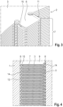
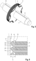
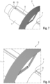
- a disk pack 2 which can be fixed in a rotationally fixed manner on a shaft 1 of an electrical machine (not shown in more detail) and has a large number of plane-parallel disks 3, 4 lying flat against one another is described below using the Figures 1 to 10
- Each of the plurality of lamellae 3, 4 has a circular opening 5 in its basic form for the Figures 5 and 9 shown shaft 1, into which a radially inwardly directed formation 6 of each lamella 3, 4 protrudes. Together, these formations 6 of the lamellae 3, 4 form a lamellar wedge 7, which is fixed in a rotationally fixed manner in a groove-shaped recess 9 of the shaft 1 delimited by lateral inner wall surfaces 8.
- each formation 6 of a first slat 3 with a side surface 11 serving as a bend 12 is followed by a second or further slat 4 with a formation 6 which, in the fixing position, does not define a contact surface 13 but rather a gap 14 to the inner wall surface 8 at a distance A.
- the side surfaces 11 of the respective first slats 3 can be bent in the fixing position into the gap 14 between the inner wall surface 8 of the recess 9 and an end face 15 of the formation 6 of the second slat 4.
- the main idea of the invention is that the bend 12 of the first lamella 3 is clamped or spread between the front surface 15 of the second lamella 4 and the inner wall surface 8 of the recess 9 in such a way that the fixing force fixes both the first lamella 3 and the second lamella 4 in the recess 9.
- the bend 12 is created by pushing or inserting the formation 6 into the recess 9
- a kink or bend line 16 is created along the front surface 15 of the second lamella 4, which is thereby fixed in a form-fitting manner.
- the fixing position is reached when the front surface 15 of the second lamella 4 forms an acute angle ⁇ of approximately 45° with an inner surface 17 of the bend 12 of the first lamella 3.
- the lamellae 3, 4 are not only centered in the recess 9 and relative to each other, but a load-bearing connection of the lamellae 3, 4 to the lamella pack 2 is also created without the need for additional connecting means, for example, adhesives are required.
- This connection of the lamellae 3, 4 to the lamella pack 2 can also be removed again for repair or recycling purposes.
- a first embodiment is shown in which all slats 3 are constructed identically and every second slat 3 is rotated in such a way that the side surfaces 11 with the angle 12 lie alternately on different sides.
- Each slat 3 thus supports the following slat 3 through the angle 12, which in turn supports and fixes the next slat 3, now on the opposite inner wall surface 8.
Landscapes
- Engineering & Computer Science (AREA)
- Power Engineering (AREA)
- Iron Core Of Rotating Electric Machines (AREA)
Applications Claiming Priority (1)
| Application Number | Priority Date | Filing Date | Title |
|---|---|---|---|
| DE102023203674.6A DE102023203674A1 (de) | 2023-04-20 | 2023-04-20 | Ein auf einer Welle drehfest fixierbares Lamellenpaket sowie eine elektrische Maschine mit einem solchen Lamellenpaket |
Publications (1)
| Publication Number | Publication Date |
|---|---|
| EP4459843A1 true EP4459843A1 (fr) | 2024-11-06 |
Family
ID=90720290
Family Applications (1)
| Application Number | Title | Priority Date | Filing Date |
|---|---|---|---|
| EP24169490.0A Pending EP4459843A1 (fr) | 2023-04-20 | 2024-04-10 | Paquet de tôles fixable de manière solidaire en rotation sur un arbre ainsi qu'une machine électrique dotée d'un tel paquet de tôles |
Country Status (3)
| Country | Link |
|---|---|
| EP (1) | EP4459843A1 (fr) |
| CN (1) | CN118826331A (fr) |
| DE (1) | DE102023203674A1 (fr) |
Citations (5)
| Publication number | Priority date | Publication date | Assignee | Title |
|---|---|---|---|---|
| JP2014176218A (ja) | 2013-03-11 | 2014-09-22 | Mitsubishi Electric Corp | 回転子および当該回転子を有する回転電機、更には当該回転子の製造方法 |
| JP2016123240A (ja) | 2014-12-25 | 2016-07-07 | アイシン・エィ・ダブリュ株式会社 | 電動機用ロータ及びその製造方法 |
| DE102015225582A1 (de) * | 2015-12-17 | 2017-06-22 | Volkswagen Aktiengesellschaft | Rotorlamellenpaket und Rotor für ein elektrisches Aggregat, insbesondere für einen Elektromotor, und Verfahren zur Herstellung eines solchen Rotors |
| EP3514921A1 (fr) | 2016-09-14 | 2019-07-24 | Hitachi Automotive Systems, Ltd. | Machine dynamo-électrique |
| DE102018205258A1 (de) * | 2018-04-09 | 2019-10-10 | Robert Bosch Gmbh | Elektrische Maschine |
Family Cites Families (3)
| Publication number | Priority date | Publication date | Assignee | Title |
|---|---|---|---|---|
| DE102007060248A1 (de) * | 2007-12-14 | 2009-06-18 | Robert Bosch Gmbh | Lamellenpaket für einen Elektromotor |
| DE102014110439A1 (de) * | 2014-07-24 | 2016-01-28 | Thyssenkrupp Presta Teccenter Ag | Rotor für einen Elektromotor |
| DE102019129822A1 (de) * | 2019-11-05 | 2021-05-06 | Metabowerke Gmbh | Vorrichtung zur Anordnung eines Stators in einem Gehäuse eines Elektromotors |
-
2023
- 2023-04-20 DE DE102023203674.6A patent/DE102023203674A1/de active Pending
-
2024
- 2024-04-10 EP EP24169490.0A patent/EP4459843A1/fr active Pending
- 2024-04-18 CN CN202410468264.3A patent/CN118826331A/zh active Pending
Patent Citations (6)
| Publication number | Priority date | Publication date | Assignee | Title |
|---|---|---|---|---|
| JP2014176218A (ja) | 2013-03-11 | 2014-09-22 | Mitsubishi Electric Corp | 回転子および当該回転子を有する回転電機、更には当該回転子の製造方法 |
| JP2016123240A (ja) | 2014-12-25 | 2016-07-07 | アイシン・エィ・ダブリュ株式会社 | 電動機用ロータ及びその製造方法 |
| DE102015225582A1 (de) * | 2015-12-17 | 2017-06-22 | Volkswagen Aktiengesellschaft | Rotorlamellenpaket und Rotor für ein elektrisches Aggregat, insbesondere für einen Elektromotor, und Verfahren zur Herstellung eines solchen Rotors |
| EP3514921A1 (fr) | 2016-09-14 | 2019-07-24 | Hitachi Automotive Systems, Ltd. | Machine dynamo-électrique |
| EP3514921B1 (fr) * | 2016-09-14 | 2022-05-04 | Hitachi Astemo, Ltd. | Machine dynamo-électrique |
| DE102018205258A1 (de) * | 2018-04-09 | 2019-10-10 | Robert Bosch Gmbh | Elektrische Maschine |
Also Published As
| Publication number | Publication date |
|---|---|
| DE102023203674A1 (de) | 2024-10-24 |
| CN118826331A (zh) | 2024-10-22 |
Similar Documents
| Publication | Publication Date | Title |
|---|---|---|
| EP2100358B1 (fr) | Rotor à aimants permanents présentant des gauchissements destinés à la fixation des aimants permanents du bloc rotor | |
| EP1702395B1 (fr) | Procede de fabrication d'un stator et stator ainsi fabrique | |
| EP3695486B1 (fr) | Machine électrique comprenant un paquet de lamelles pour fixer un aimant et paquet de lamelles destiné à être utilisé avec une telle machine | |
| EP1756928B1 (fr) | Moteur synchrone | |
| DE102011078054A1 (de) | Lamellenpaket mit Magnetfixiernasen für einen Rotor oder Stator einer Elektromaschine | |
| DE102008026648A1 (de) | Rotor für einen elektronisch kommutierten Elektromotor, Verfahren zur Herstellung eines solchen Rotors sowie bei der Herstellung eines solchen Rotors verwendbares Zwischenprodukt | |
| DE102015012912B4 (de) | Rotoraufbau mit formschlüssig befestigten Blechpaketen | |
| WO2005114813A1 (fr) | Noyau feuillete produit a base de segments | |
| DE102017201178A1 (de) | Maschinenbauelement sowie Verfahren zum Herstellen eines Maschinenbauelements | |
| DE2837797A1 (de) | Verfahren und vorrichtung zum herstellen eines stators fuer einen elektrischen generator | |
| EP2338215A2 (fr) | Ensemble de lamelles d'un rotor d'une machine électrique | |
| WO2018138187A1 (fr) | Anneau de noyau feuilleté comprenant une pluralité de segments d'anneau de noyau feuilleté, et rotor | |
| WO2021228493A1 (fr) | Procédé de fabrication d'un rotor et rotor | |
| EP0100871B1 (fr) | Procédé de production d'un paquet de tôle, notamment pour l'induit de machines et appareils électriques | |
| DE102020204576A1 (de) | Lamellenpaket für eine elektrische Maschine, sowie eine elektrische Maschine aufweisend ein Lamellenpaket, und Verfahren zum Herstellen eines Statorgrundkörpers | |
| DE102018204436A1 (de) | Verfahren zur Montage von Lamellen- oder Blechpaketen auf einer Hohlwelle sowie ein auf diese Weise hergestellter Rotor für eine elektrische Maschine | |
| DE102019202563A1 (de) | Rotor für eine elektrische Maschine mit einem mehrteiligen Rotorträger | |
| DE102021002130A1 (de) | Verfahren zum Montieren eines Rotors einer elektrischen Maschine mittels verdrehter Blechlagen, sowie ein entsprechender Rotor | |
| EP4459843A1 (fr) | Paquet de tôles fixable de manière solidaire en rotation sur un arbre ainsi qu'une machine électrique dotée d'un tel paquet de tôles | |
| DE102021204845A1 (de) | Lamellenpaket für eine elektrische Maschine sowie Verfahren zur Fertigung des Lamellenpakets | |
| DE102021200809A1 (de) | Eine Rotorlamelle, ein Rotorblechpaket, ein Rotor und ein Verfahren zum Fertigen eines Rotors | |
| DE102015225582A1 (de) | Rotorlamellenpaket und Rotor für ein elektrisches Aggregat, insbesondere für einen Elektromotor, und Verfahren zur Herstellung eines solchen Rotors | |
| DE102014206847A1 (de) | Stator einer rotierenden elektrischen Maschine | |
| EP4525273A1 (fr) | Paquet de lamelles doté d'un assemblage de languettes de serrage | |
| DE102019202566A1 (de) | Rotor für eine elektrische Maschine mit Kühlkanälen |
Legal Events
| Date | Code | Title | Description |
|---|---|---|---|
| PUAI | Public reference made under article 153(3) epc to a published international application that has entered the european phase |
Free format text: ORIGINAL CODE: 0009012 |
|
| STAA | Information on the status of an ep patent application or granted ep patent |
Free format text: STATUS: THE APPLICATION HAS BEEN PUBLISHED |
|
| AK | Designated contracting states |
Kind code of ref document: A1 Designated state(s): AL AT BE BG CH CY CZ DE DK EE ES FI FR GB GR HR HU IE IS IT LI LT LU LV MC ME MK MT NL NO PL PT RO RS SE SI SK SM TR |
|
| STAA | Information on the status of an ep patent application or granted ep patent |
Free format text: STATUS: REQUEST FOR EXAMINATION WAS MADE |
|
| 17P | Request for examination filed |
Effective date: 20250506 |