EP4459866A1 - Filtre matériel emc pour appareil de gestion de flotte - Google Patents
Filtre matériel emc pour appareil de gestion de flotte Download PDFInfo
- Publication number
- EP4459866A1 EP4459866A1 EP24171430.2A EP24171430A EP4459866A1 EP 4459866 A1 EP4459866 A1 EP 4459866A1 EP 24171430 A EP24171430 A EP 24171430A EP 4459866 A1 EP4459866 A1 EP 4459866A1
- Authority
- EP
- European Patent Office
- Prior art keywords
- filter
- emc
- signals
- filter stage
- fleet management
- Prior art date
- Legal status (The legal status is an assumption and is not a legal conclusion. Google has not performed a legal analysis and makes no representation as to the accuracy of the status listed.)
- Pending
Links
Images



Classifications
-
- H—ELECTRICITY
- H02—GENERATION; CONVERSION OR DISTRIBUTION OF ELECTRIC POWER
- H02M—APPARATUS FOR CONVERSION BETWEEN AC AND AC, BETWEEN AC AND DC, OR BETWEEN DC AND DC, AND FOR USE WITH MAINS OR SIMILAR POWER SUPPLY SYSTEMS; CONVERSION OF DC OR AC INPUT POWER INTO SURGE OUTPUT POWER; CONTROL OR REGULATION THEREOF
- H02M1/00—Details of apparatus for conversion
- H02M1/44—Circuits or arrangements for compensating for electromagnetic interference in converters or inverters
-
- H—ELECTRICITY
- H02—GENERATION; CONVERSION OR DISTRIBUTION OF ELECTRIC POWER
- H02M—APPARATUS FOR CONVERSION BETWEEN AC AND AC, BETWEEN AC AND DC, OR BETWEEN DC AND DC, AND FOR USE WITH MAINS OR SIMILAR POWER SUPPLY SYSTEMS; CONVERSION OF DC OR AC INPUT POWER INTO SURGE OUTPUT POWER; CONTROL OR REGULATION THEREOF
- H02M1/00—Details of apparatus for conversion
- H02M1/12—Arrangements for reducing harmonics from AC input or output
- H02M1/123—Suppression of common mode voltage or current
-
- B—PERFORMING OPERATIONS; TRANSPORTING
- B60—VEHICLES IN GENERAL
- B60H—ARRANGEMENTS OF HEATING, COOLING, VENTILATING OR OTHER AIR-TREATING DEVICES SPECIALLY ADAPTED FOR PASSENGER OR GOODS SPACES OF VEHICLES
- B60H1/00—Heating, cooling or ventilating devices
- B60H1/00357—Air-conditioning arrangements specially adapted for particular vehicles
- B60H1/00364—Air-conditioning arrangements specially adapted for particular vehicles for caravans or trailers
-
- B—PERFORMING OPERATIONS; TRANSPORTING
- B60—VEHICLES IN GENERAL
- B60H—ARRANGEMENTS OF HEATING, COOLING, VENTILATING OR OTHER AIR-TREATING DEVICES SPECIALLY ADAPTED FOR PASSENGER OR GOODS SPACES OF VEHICLES
- B60H1/00—Heating, cooling or ventilating devices
- B60H1/32—Cooling devices
- B60H1/3204—Cooling devices using compression
- B60H1/3205—Control means therefor
-
- B—PERFORMING OPERATIONS; TRANSPORTING
- B60—VEHICLES IN GENERAL
- B60P—VEHICLES ADAPTED FOR LOAD TRANSPORTATION OR TO TRANSPORT, TO CARRY, OR TO COMPRISE SPECIAL LOADS OR OBJECTS
- B60P3/00—Vehicles adapted to transport, to carry or to comprise special loads or objects
- B60P3/20—Refrigerated goods vehicles
-
- F—MECHANICAL ENGINEERING; LIGHTING; HEATING; WEAPONS; BLASTING
- F25—REFRIGERATION OR COOLING; COMBINED HEATING AND REFRIGERATION SYSTEMS; HEAT PUMP SYSTEMS; MANUFACTURE OR STORAGE OF ICE; LIQUEFACTION SOLIDIFICATION OF GASES
- F25D—REFRIGERATORS; COLD ROOMS; ICE-BOXES; COOLING OR FREEZING APPARATUS NOT OTHERWISE PROVIDED FOR
- F25D29/00—Arrangement or mounting of control or safety devices
-
- H—ELECTRICITY
- H02—GENERATION; CONVERSION OR DISTRIBUTION OF ELECTRIC POWER
- H02M—APPARATUS FOR CONVERSION BETWEEN AC AND AC, BETWEEN AC AND DC, OR BETWEEN DC AND DC, AND FOR USE WITH MAINS OR SIMILAR POWER SUPPLY SYSTEMS; CONVERSION OF DC OR AC INPUT POWER INTO SURGE OUTPUT POWER; CONTROL OR REGULATION THEREOF
- H02M1/00—Details of apparatus for conversion
- H02M1/12—Arrangements for reducing harmonics from AC input or output
- H02M1/126—Arrangements for reducing harmonics from AC input or output using passive filters
-
- H—ELECTRICITY
- H03—ELECTRONIC CIRCUITRY
- H03H—IMPEDANCE NETWORKS, e.g. RESONANT CIRCUITS; RESONATORS
- H03H1/00—Constructional details of impedance networks whose electrical mode of operation is not specified or applicable to more than one type of network
- H03H1/0007—Constructional details of impedance networks whose electrical mode of operation is not specified or applicable to more than one type of network of radio frequency interference filters
-
- H—ELECTRICITY
- H03—ELECTRONIC CIRCUITRY
- H03H—IMPEDANCE NETWORKS, e.g. RESONANT CIRCUITS; RESONATORS
- H03H7/00—Multiple-port networks comprising only passive electrical elements as network components
- H03H7/01—Frequency selective two-port networks
- H03H7/0115—Frequency selective two-port networks comprising only inductors and capacitors
-
- H—ELECTRICITY
- H03—ELECTRONIC CIRCUITRY
- H03H—IMPEDANCE NETWORKS, e.g. RESONANT CIRCUITS; RESONATORS
- H03H1/00—Constructional details of impedance networks whose electrical mode of operation is not specified or applicable to more than one type of network
- H03H2001/0021—Constructional details
- H03H2001/0057—Constructional details comprising magnetic material
Definitions
- the disclosure relates to the field of electro-mechanical control systems.
- the disclosure relates to an electromagnetic compatibility (EMC) filter to reduce electromagnetic interference (EMI) generated by one or more electronic equipment in an electro-mechanical control system.
- EMC electromagnetic compatibility
- the fleet management systems can track or manage a fleet of vehicles including refrigeration transport vehicles.
- Each of the fleet management systems includes a fleet module, which helps businesses in optimizing their fleet utilization, reduce operating costs, and improve driver safety.
- the EN12830 standard provides a set of technical requirements for temperature monitoring devices for ensuring the safety and quality of temperature-sensitive products during transport, storage, and distribution.
- One of the major problems of being non-compliant with the EN12830 standard is the fleet modules' EMC compatibility, namely the ability to reliably pass tests associated with Electromagnetic Compatibility (EMC) standards such as EN61000-4-3, EN61000-4-6, and EN61000-4-8.
- EMC Electromagnetic Compatibility
- EN61000-4-3, EN61000-4-6, and EN61000-4-8 This can lead to a number of issues, including disruption of electronic boards of the fleet modules in the vicinity due to conductive emission issues. Additionally, the fleet modules may also lose communication due to external EMC noise.
- the above-mentioned problems may affect the fleet modules reliability. Also, the above-mentioned problems pose a challenge as the fleet modules may not be able to be marketed without passing the aforementioned tests associated with the EMC standards and associated reliability issues.
- an electromagnetic compatibility (EMC) filter that includes a first connection port configured to receive one or more input signals from a plurality of sensors and an input power signal.
- the EMC filter further includes a first filter stage, a second filter stage, and a third filter stage including a plurality of ferrite beads and a plurality of capacitors.
- the first filter stage is configured to filter the received input power signal and the second filter stage is configured to filter one or more ground output signals of the EMC filter.
- the third filter stage is configured to filter the received one or more input signals to remove EMC noises from the received one or more input signals.
- the EMC filter further includes a second connection port configured to output the filtered one or more input signals and the filtered input power signal to a fleet management apparatus.
- each of the first filter stage and the second filter stage is configured in a common mode inductance configuration.
- an inductance value of each of the first filter stage and the second filter stage in the common mode inductance configuration is 51 ⁇ H with a tolerance of +/- 30% at a frequency of 1 Khz.
- the received one or more input signals include at least controller area network (CAN) signals, output signals of one or more temperature sensors, a plurality of digital signals, power supply voltage or current signals associated with the one or more temperature sensors, and fuel level sensor circuit (FLS-C) signals.
- CAN controller area network
- FLS-C fuel level sensor circuit
- the third filter stage may be further configured to filter the power supply voltage or the current signals using a first ferrite bead of the plurality of ferrite beads and a first capacitor of the plurality of capacitors.
- a capacitance value of the first capacitor is 68 pF with a tolerance of +/- 5%.
- the third filter stage may be further configured to filter the output signals of the one or more temperature sensors using a second ferrite bead of the plurality of ferrite beads and a second capacitor of the plurality of capacitors, wherein a capacitance value of the second capacitor is one of 68 pF with the tolerance of +/- 5% or 100 nF with a tolerance of +/- 10%.
- the third filter stage may be further configured to filter the plurality of digital signals using a third ferrite bead of the plurality of ferrite beads and a third capacitor of the plurality of capacitors, wherein a capacitance value of the third capacitor is 100 nF with the tolerance of +/-10%.
- the third filter stage may be further configured to filter the FLS-C signals using a fourth ferrite bead of the plurality of ferrite beads and a fourth capacitor of the plurality of capacitors, wherein a capacitance value of the fourth capacitor is 100 nF with the tolerance of +/-10%.
- a resistance value of each ferrite bead of the plurality of ferrite beads is 600 ⁇ with a tolerance of +/-25% at a frequency of 100MHz.
- a fleet management system that includes a refrigeration unit including a plurality of sensors, a fleet management module configured to control setting of the refrigeration unit, and an electromagnetic compatibility (EMC) filter between the refrigeration unit and the fleet management module.
- the EMC filter includes a first connection port configured to receive one or more input signals from the plurality of sensors and an input power signal.
- the EMC filter further includes a first filter stage configured to filter the received input power signal and a second filter stage configured to filter one or more ground output signals of the EMC filter.
- the EMC filter includes a third filter stage that includes a plurality of ferrite beads and a plurality of capacitors.
- the third filter stage is configured to filter the received one or more input signals to remove EMC noises from the received one or more input signals.
- the EMC filter includes a second connection port configured to output the filtered one or more input signals and the filtered input power signal to the fleet management module, wherein the fleet management module is configured to control the setting of the refrigeration unit based on the filtered one or more input signals.
- a refrigerated trailer that includes a refrigeration unit including a plurality of sensors, a fleet management module configured to control setting of the refrigeration unit, and an electromagnetic compatibility (EMC) filter between the refrigeration unit and the fleet management module.
- the EMC filter includes a first connection port configured to receive one or more input signals from the plurality of sensors and an input power signal.
- the EMC filter further includes a first filter stage configured to filter the received input power signal and a second filter stage configured to filter one or more ground output signals of the EMC filter.
- the EMC filter includes a third filter stage that includes a plurality of ferrite beads and a plurality of capacitors.
- the third filter stage is configured to filter the received one or more input signals to remove EMC noises from the received one or more input signals.
- the EMC filter includes a second connection port configured to output the filtered one or more input signals and the filtered input power signal to the fleet management module, wherein the fleet management module is configured to control the setting of the refrigeration unit based on the filtered one or more input signals.
- any terms used herein such as but not limited to “includes”, “comprises”, “has”, “have”, and grammatical variants thereof do not specify an exact limitation or restriction and certainly do not exclude the possible addition of one or more features or elements, unless otherwise stated, and must not be taken to exclude the possible removal of one or more of the listed features and elements, unless otherwise stated with the limiting language “must comprise” or “needs to include”.
- unit used herein may imply a unit including, for example, one of hardware, software, and firmware or a combination of two or more of them.
- the “unit” may be interchangeably used with a term such as logic, a logical block, a component, a circuit, and the like.
- the “unit” may be a minimum system component for performing one or more functions or may be a part thereof.
- FIG. 1 illustrates an example system environment 100 of an electro-mechanical control system.
- the system environment 100 includes a fleet management apparatus 101, an electromagnetic compatibility (EMC) filter 103, a global navigation satellite system (GNSS) antenna 105, and a global system for mobile communications (GSM) antenna 107 connected to the fleet management apparatus 101, a refrigeration trailer 109 comprising a refrigeration unit attached to a truck 117-, a controller area network (CAN) bus 111 connected to a first input port 101-1 of the fleet management apparatus 101, and a telematics antenna 113 connected to a second input port 101-2 of the fleet management apparatus 101.
- the refrigeration trailer 109 may be pulled by the truck 117 in order to transport perishable goods optionally in combination with non-perishable goods from one location to another location.
- refrigerated trailer comprising a refrigeration unit
- this terminology is intended to include situations in which a refrigeration unit is associated with the cargo portion of a truck or van such as in a light commercial vehicle (sometimes referred to as a box truck). In these situations, the refrigerated cargo space is equivalent to the refrigerated trailer as used herein.
- the refrigeration unit disposed on the refrigeration trailers 109 is connected to the fleet management apparatus 101 via the CAN bus 111 (as shown in FIG. 1 ), the telematics antenna 113, or a combination thereof.
- the refrigeration unit provides a conditioned environment to the interior of the refrigerated trailer 109.
- the EMC filter 103 includes a first connection port 103-1 and a second connection port 103-2.
- the first connection port 103-1 of the EMC filter 103 may be configured to receive one or more input signals 119 from the plurality of sensors and an input power signal 115 from the power supply line 121 powering the fleet management apparatus 101.
- the second connection port 103-2 of the EMC filter 103 is connected to a third input port 101-3 of the fleet management apparatus 101.
- the fleet management apparatus 101 is configured to communicate with various components and the plurality of sensors that are installed in the refrigeration trailer 109 (as part of the refrigeration unit) via the CAN bus 111 and/or the telematics antenna 113.
- the fleet management apparatus 101 may be configured to receive sensor inputs from the plurality of sensors installed in the refrigeration trailer 109.
- the fleet management apparatus 101 may also be configured to monitor, manage, and control cooling parameters or setting of the refrigeration unit based on the received sensor inputs.
- the fleet management apparatus 101 may also be referred to as a fleet management module without any deviation from the scope of the disclosure.
- the EMC filter 103 is connected between the fleet management apparatus 101 and the refrigeration unit.
- the EMC filter 103 may also be connected to electronic components (e.g., temperature sensors, fuel sensors, etc.) associated with the refrigeration unit.
- the EMC filter 103 is configured to filter electromagnetic interference (EMI) from one or more input signals 119 from a plurality of sensors (not shown in FIG. 1 ) and input power signals received from a power supply line 121 powering the fleet management apparatus 101.
- EMI electromagnetic interference
- the filtering operation of the EMC filter 103 to filter the EMI ensures that the electrical system of the refrigerated trailer 109 including a temperature control system, control modules, and sensors that monitor and regulate the operation of the refrigerated trailer 109, may be operated correctly.
- the EMC filter 103 is configured to filter out any unwanted external EMC noises that may be present in the system environment 100 and self-generated emission radiation.
- the self-generated emission radiation may be radiation generated by the EMC filter 103.
- the first connection port 103-1 of the EMC filter 103 is configured to receive one or more input signals 119 from the plurality of sensors and an input power signal 115 from the power supply line 121 powering the fleet management apparatus 101.
- the one or more input signals 119 may include, but not limited to, CAN signals, output signals of one or more temperature sensors installed inside the refrigeration trailer 109, a plurality of digital signals, power supply voltage or current signals associated with the one or more temperature sensors, fuel level sensor circuit (FLS-C) signals, state of battery charge signals, and the like.
- the FLS-C signals correspond to electrical signals generated by a fuel level sensor of a fuel system of refrigeration unit associated with the trailer 109. Accordingly, the fleet management apparatus 101 may control the setting of the refrigeration unit.
- the input power signal 115 powering the fleet management apparatus 101 may cause an electrical disturbance to the fleet management apparatus 101.
- the input power signal 115 may generate voltage spikes, switching transients, and/or electromagnetic radiation.
- the fleet management apparatus 101 may pick up the electromagnetic radiation.
- the pickup of the electromagnetic radiation by the fleet management apparatus 101 may result in the generation of the EMI.
- the generated EMI may cause the fleet management apparatus 101 to malfunction or work incorrectly.
- the GNSS antenna 105 is configured to receive signals from one or more satellite systems.
- the GNSS antenna 105 may be designed to receive signals from multiple satellites simultaneously, even in adverse weather conditions.
- the fleet management apparatus 101 is configured to determine the location, speed, and direction of the trailer 109 based on the received signals from the one or more satellite systems.
- the GSM antenna 107 is configured to communicate with a cellular network to provide real-time updates on the refrigeration trailer's location, status, and other information associated with the refrigeration trailer 109.
- the GSM antenna 105 may be configured to operate reliably in areas with weak cellular signals.
- the GSM antenna 107 may be connected to a cellular modem or a router, which allows the fleet management apparatus 101 to send and receive data over the cellular network.
- the telematics antenna 113 is configured to provide real-time communication between the refrigerated trailer 109 and the fleet management apparatus 101.
- the real-time communication allows the fleet management apparatus 101 to send and receive data related to the refrigeration trailer's location, status, and other information associated with the with the refrigeration trailer's operation.
- the EMC filter 103 may further include a plurality of filtering components in order to reduce the EMI caused due to the electromagnetic radiation propagation and the input power signal 115.
- the EMC filter 103 includes a first filter stage 301, a second filter stage 303, and a third filter stage 305 (as shown in FIG. 3 ) in addition to the first connection port 103-1 and the second connection port 103-2.
- the first filter stage 301 includes a first common mode inductance filter 200-1 (as shown in FIG. 2A ) and the second filter stage 303 includes a second common mode inductance filter 200-2 (as shown in FIG. 2B ).
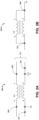
- FIG. 2A illustrates a schematic diagram of the first common mode inductance filter 200-1 for reducing the EMI generated due to the input power signal 115.
- the first common mode inductance filter 200-1 includes a common mode inductor L1.
- the common mode inductor L1 receives the input power signal 115 between terminals 1 and 2 of the common mode inductor L1.
- the input power signal 115 includes a line voltage signal 203 of 12V DC, which may be applied at terminal 1 of the common mode inductor L1.
- a ground voltage signal 201 corresponding to the line voltage signal 203 of 12 V may be applied at terminal 2 of the common mode inductor L1.
- the common mode inductor L1 is made up of two inductors wound on a common magnetic core, with both inductors connected in series with the input and output lines corresponding to the input power signal 115.
- the common mode inductor L1 filters the EMI noise that may be present at the input terminal corresponding to the input power signal 115.
- the EMI noise flows through both inductors in the same direction.
- the flow of the EMI noise in the same direction may generate a magnetic field that may oppose the EMI noise.
- the generated magnetic field helps in the reduction of the EMI noise through the common mode inductor L1.
- the common mode inductor L1 further filters the line voltage signal 203 and outputs a filtered 12V DC output signal 205 at terminal 4 of the common mode inductor L1.
- a filtered ground signal 207 may be received at terminal 3 of the common mode inductor L1.
- the reference ground signal 209 provides a reference voltage for the one or more input signals received from the plurality of sensors and serves as a return path for the current.
- the reference voltage becomes unstable when the EMI may be present in the reference ground signal 209 of the electronic components associated with the fleet management apparatus 101.
- the instability of the reference voltage results in distorted signals and increased noise levels.
- the presence of the EMI in the reference ground signal 209 also leads to ground loops, which occur when there are multiple ground paths in the EMC filter's circuit. The ground loops may cause the current to flow through the reference ground signal 209, which may create noise and interfere with the functional operability of the fleet management apparatus 101.
- FIG. 2B illustrates a schematic diagram of a second common mode inductance filter 200-2 for reducing the EMI generated due to the reference ground signal.
- the second common mode inductance filter 200-2 includes a common mode inductor L2.
- the common mode inductor L2 is made up of two inductors wounded on a common magnetic core, with both inductors connected in series. Terminal 1 and terminal 2 of the common mode inductor L2 are connected to each other and the reference ground signal 209 may be inputted to commonly connected terminals. Terminals 3 and 4 of the common mode inductor L2 are also connected to each other. The terminals 3 and 4 of the common mode inductor L2 are configured to output the filtered ground signal 207.
- the common mode inductor L2 filters the EMI noise that may be present in the reference ground signal. When the EMI noise flows through both the inductors of the common mode inductor L2 in the same direction, a magnetic field may be created that may oppose the EMI noise. The created magnetic field reduces the EMI noise through the common mode inductor L2.
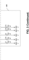
- FIG. 3 illustrates a schematic diagram of the EMC filter 103.
- the first connection port 103-1 of the EMC filter 103 is configured to receive the one or more input signals from the plurality of sensors and the input power signal 115.
- the input power signal 115 refers to a power supply signal for the fleet management apparatus 101.
- the first connection port 103-1 may be, for example, a 20-pin connection port as shown in FIG. 3 .
- differential signals of the CAN bus 111 for example, CAN High (CAN H) and CAN Low (CAN L) may be received at pin-2 and pin 12 of the first connection port 103-1.
- the first filter stage 301 is configured to filter the received input power signal 115.
- the first filter stage 301 is further configured to output a filtered 12V DC output signal 205 for the fleet management apparatus 101.
- an inductance value of each inductor of the first filter stage 301 may be 51 ⁇ H.
- the inductance value of each inductor of the first filter stage 301 may have a tolerance of +/- 30% at a frequency of 1Khz.
- the inductance value of each inductor of the first filter stage 301 may be varied in a range of 35.7 ⁇ H to 66.3 ⁇ H.
- the first filter stage 301 receives the line voltage signal 203 of 12V DC via pin-11 of the first connection port 103-1 and the ground voltage signal 201 via pin-1 of the first connection port 103-1.
- the first filter stage 301 outputs the filtered 12V DC signal via pin-11 of the second connection port 103-2.
- the second filter stage 303 is configured to filter the reference ground signal 209 of the EMC filter 103.
- the second filter stage 303 may filter a plurality of reference ground signals 209 of the EMC filter 103.
- the second filter stage 303 is configured to output the filtered ground signal 207.
- an inductance value of each inductor of the second filter stage may be 51 ⁇ H with the tolerance of +/- 30% at the frequency of 1Khz.
- the inductance value of each of the inductor of the second filter stage 303 may be varied in the range of 35.7 ⁇ H to 66.3 ⁇ H.
- the second filter stage 303 filters the reference ground signal 209 and outputs the filtered ground signal 207 to pin-1 of the second connection port 103-2.
- the first filter stage 301 and the second filter stage 303 provide various technical advantages, for example, the configuration of each of the first filter stage 301 and the second filter stage 303 does not affect a signal rise time because of the magnetic field compensation across the first common mode inductance filter 200-1 and the second common mode inductance filter 200-2.
- the signal rise time means a time taken by the signal to transit from a low state to a high state, or vice versa. Since, each of the first common mode inductance filter 200-1 and the second common mode inductance filter 200-2 have windings that are magnetically coupled, the influence of the wanted signal is restricted. Further, the configuration of each of the first common mode inductance filter 200-1 and the second common mode inductance filter 200-2 restricts an occurrence of the saturation from the DC current because of the magnetic coupling.
- the third filter stage 305 includes a plurality of ferrite beads (FB3, FB5, FB7, FB10, FB13, FB14, FB17, FB18) and a plurality of capacitors (C3, C 5, C7, C10, C13, C14, C17, C18).
- the third filter stage 305 receives one or more input signals from the first connection port 103-1. Further, the third filter stage 305 outputs filtered signals of the received one or more input signals to the second connection port 103-2. In particular, the third filter stage 305 filters the received one or more input signals to remove EMC noises from the received one or more input signals. More particularly, the third filter stage 305 reduces the amount of the EMI picked up by the plurality of sensors.
- Each ferrite bead of the plurality of ferrite beads of the third filter stage 305 is a passive component made of a ceramic material containing iron oxide.
- Each ferrite bead of the plurality of ferrite beads is configured to filter out high-frequency noise and interference while allowing lower frequency signals to pass through.
- each ferrite bead of the plurality of ferrite beads is configured to filter out the EMI in the range of 1 MHz to 1 GHz.
- the plurality of capacitors of the third filter stage 305 is used in combination with the plurality of ferrite beads of the third filter stage 305 for filtering the one or more input signals received from the plurality of sensors.
- the plurality of ferrite beads is placed in series with respect to a signal line carrying the received one or more input signals.
- the corresponding capacitors of the plurality of capacitors are placed in parallel to the signal line carrying the received one or more input signals.
- Each combination of a corresponding ferrite bead of the plurality of ferrite beads and a corresponding capacitor of the plurality of capacitors filters out the high-frequency noise and the EMI while allowing the sensor signal to pass through the third filter stage 305 with minimal distortion.
- a resistance value of each ferrite bead of the plurality of ferrite beads may be 600 ⁇ with a tolerance of +/-25% at a frequency of 100MHz at 200mA of rated current value.
- the resistance value of each ferrite bead of the plurality of ferrite beads may be varied in the range of 450 ⁇ to 750 ⁇ .
- a capacitance value of each of the plurality of capacitors may be 68 pF or 100 nF with a tolerance of +/- 5% and +/- 10%, respectively.
- each of the plurality of capacitors may be varied in a range of 64.6 pF to 71.4 pF and in a range of 90 nF to 110 nF, respectively.
- the capacitance value of each of the plurality of capacitors may be varied in a range of 64.6 pF to 71.4 pF and in a range of 90 nF to 110 nF, respectively.
- the CAN High and CAN Low signals are filtered using a combination of (FB2, C2) and (FB12, C12), respectively.
- the filtered signals are outputted at pin-2 and pin-12 of the second connection port.
- connection port 103-2 is configured to output the filtered one or more input signals and the filtered input power signal to the fleet management apparatus 101.
- FIG. 4 illustrates a graphical representation of typical impedance characteristics of the common mode inductors of the first common mode inductance filter 200-1 and the second common mode inductance filter 200-2 of FIGs. 2A and 2B .
- FIG. 4 illustrates an impedance characteristics curve of the common mode inductors as a variation of common mode impedance with respect to an operating frequency of the common mode inductors.
- the common mode inductors exhibit an inductive characteristic up to a resonance frequency.
- the inductive characteristics mean that the impedance of the common mode inductors increases as the frequency rises.
- the common mode inductors exhibit a capacitive characteristic beyond the resonance frequency.
- the capacitive characteristics means the impedance of the common mode inductors decreases as the frequency rises. At all the frequencies higher than the resonance frequency, the common mode inductors work as a capacitive filter.
Landscapes
- Engineering & Computer Science (AREA)
- Power Engineering (AREA)
- Physics & Mathematics (AREA)
- Mechanical Engineering (AREA)
- Thermal Sciences (AREA)
- Chemical & Material Sciences (AREA)
- Transportation (AREA)
- Public Health (AREA)
- Health & Medical Sciences (AREA)
- Combustion & Propulsion (AREA)
- General Engineering & Computer Science (AREA)
- Electromagnetism (AREA)
- Filters And Equalizers (AREA)
- Fuzzy Systems (AREA)
- Mathematical Physics (AREA)
- Software Systems (AREA)
- Theoretical Computer Science (AREA)
Applications Claiming Priority (1)
| Application Number | Priority Date | Filing Date | Title |
|---|---|---|---|
| US202363497553P | 2023-04-21 | 2023-04-21 |
Publications (1)
| Publication Number | Publication Date |
|---|---|
| EP4459866A1 true EP4459866A1 (fr) | 2024-11-06 |
Family
ID=90810975
Family Applications (1)
| Application Number | Title | Priority Date | Filing Date |
|---|---|---|---|
| EP24171430.2A Pending EP4459866A1 (fr) | 2023-04-21 | 2024-04-19 | Filtre matériel emc pour appareil de gestion de flotte |
Country Status (3)
| Country | Link |
|---|---|
| US (1) | US20240356533A1 (fr) |
| EP (1) | EP4459866A1 (fr) |
| CN (1) | CN118826466A (fr) |
Families Citing this family (1)
| Publication number | Priority date | Publication date | Assignee | Title |
|---|---|---|---|---|
| EP4575223A1 (fr) * | 2023-12-19 | 2025-06-25 | Nordex Energy SE & Co. KG | Système pour éolienne et éolienne |
Citations (4)
| Publication number | Priority date | Publication date | Assignee | Title |
|---|---|---|---|---|
| US5969583A (en) * | 1996-12-23 | 1999-10-19 | Acuson Corporation | Common-mode EMI filter with a separately wound ground winding |
| US7667988B2 (en) * | 2004-07-23 | 2010-02-23 | Schaffner Emv Ag | Filter |
| US20100303263A1 (en) * | 2007-11-29 | 2010-12-02 | Hiensch Innovations B.V. | Electrostatic Speaker System |
| KR20200102785A (ko) * | 2019-02-22 | 2020-09-01 | 한온시스템 주식회사 | Lin 통신 기반 전동 압축기의 인버터를 위한 emc 필터 |
-
2024
- 2024-04-18 CN CN202410467270.7A patent/CN118826466A/zh active Pending
- 2024-04-18 US US18/638,913 patent/US20240356533A1/en active Pending
- 2024-04-19 EP EP24171430.2A patent/EP4459866A1/fr active Pending
Patent Citations (4)
| Publication number | Priority date | Publication date | Assignee | Title |
|---|---|---|---|---|
| US5969583A (en) * | 1996-12-23 | 1999-10-19 | Acuson Corporation | Common-mode EMI filter with a separately wound ground winding |
| US7667988B2 (en) * | 2004-07-23 | 2010-02-23 | Schaffner Emv Ag | Filter |
| US20100303263A1 (en) * | 2007-11-29 | 2010-12-02 | Hiensch Innovations B.V. | Electrostatic Speaker System |
| KR20200102785A (ko) * | 2019-02-22 | 2020-09-01 | 한온시스템 주식회사 | Lin 통신 기반 전동 압축기의 인버터를 위한 emc 필터 |
Non-Patent Citations (1)
| Title |
|---|
| JOSEPH CARR: "Introduction to the EMI problem", THE TECHNICIAN'S EMI HANDBOOK, vol. 1, 15 June 2000 (2000-06-15), pages 1 - 247, XP040426033 * |
Also Published As
| Publication number | Publication date |
|---|---|
| US20240356533A1 (en) | 2024-10-24 |
| CN118826466A (zh) | 2024-10-22 |
Similar Documents
| Publication | Publication Date | Title |
|---|---|---|
| EP4459866A1 (fr) | Filtre matériel emc pour appareil de gestion de flotte | |
| US10063209B2 (en) | Noise filter | |
| CN108649989B (zh) | 具有远程天线的nfc读取器 | |
| CN108399345B (zh) | 具有自动调谐器的nfc读取器 | |
| US20110234337A1 (en) | Filter circuit for differential communication | |
| CN1707979B (zh) | 降低来自电子模块的幅射发射的设备 | |
| CN219287481U (zh) | 滤波电路及电子设备 | |
| CN210867501U (zh) | 一种电动助力转向系统控制器的电源接口滤波电路 | |
| US11283485B2 (en) | Circuit for signal connection, device for inductive power transfer and for signal transmission | |
| US20100102847A1 (en) | Modulated supply spread spectrum | |
| CN210536290U (zh) | 一种车载以太网接口滤波保护电路 | |
| EP3772185B1 (fr) | Dispositif de communication en champ proche | |
| CN219322277U (zh) | 用于车载直流母线的电磁兼容滤波器和逆变器 | |
| US7382597B2 (en) | Method and apparatus for a bondwire decoupling filter for an integrated voltage regulator and transceiver | |
| WO2024109802A1 (fr) | Circuit de filtre et dispositif électronique | |
| US20090058559A1 (en) | Microprocessor common-mode emissions reduction circuit | |
| JP2008079386A (ja) | 自動車用電源装置 | |
| JP7764355B2 (ja) | 電源重畳通信装置および電源重畳通信システム | |
| CN111654302A (zh) | 基于汽车收音天线共用天线的车载网络通讯设备及方法 | |
| CN219041629U (zh) | 供电系统、车辆诊断仪 | |
| CN100442672C (zh) | 用于集成调压器和收发机的接合线去耦滤波器的方法和设备 | |
| CN118074645A (zh) | 滤波电路及电子设备 | |
| CN2870411Y (zh) | 可抗电磁辐射干扰的汽车音响 | |
| CN116345882A (zh) | 多合一电动汽车控制器的电磁兼容性系统 | |
| WO2024187025A2 (fr) | Système de charge de porte |
Legal Events
| Date | Code | Title | Description |
|---|---|---|---|
| PUAI | Public reference made under article 153(3) epc to a published international application that has entered the european phase |
Free format text: ORIGINAL CODE: 0009012 |
|
| STAA | Information on the status of an ep patent application or granted ep patent |
Free format text: STATUS: THE APPLICATION HAS BEEN PUBLISHED |
|
| AK | Designated contracting states |
Kind code of ref document: A1 Designated state(s): AL AT BE BG CH CY CZ DE DK EE ES FI FR GB GR HR HU IE IS IT LI LT LU LV MC ME MK MT NL NO PL PT RO RS SE SI SK SM TR |
|
| STAA | Information on the status of an ep patent application or granted ep patent |
Free format text: STATUS: REQUEST FOR EXAMINATION WAS MADE |
|
| 17P | Request for examination filed |
Effective date: 20250506 |