EP4461409A2 - Kreiselbrecher mit selbstausrichtenden hauptwellenmerkmalen und verfahren zur montage davon - Google Patents
Kreiselbrecher mit selbstausrichtenden hauptwellenmerkmalen und verfahren zur montage davon Download PDFInfo
- Publication number
- EP4461409A2 EP4461409A2 EP24202284.6A EP24202284A EP4461409A2 EP 4461409 A2 EP4461409 A2 EP 4461409A2 EP 24202284 A EP24202284 A EP 24202284A EP 4461409 A2 EP4461409 A2 EP 4461409A2
- Authority
- EP
- European Patent Office
- Prior art keywords
- dust
- mainshaft
- bonnet
- gyratory crusher
- chamfer
- Prior art date
- Legal status (The legal status is an assumption and is not a legal conclusion. Google has not performed a legal analysis and makes no representation as to the accuracy of the status listed.)
- Pending
Links
Images





Classifications
-
- B—PERFORMING OPERATIONS; TRANSPORTING
- B02—CRUSHING, PULVERISING, OR DISINTEGRATING; PREPARATORY TREATMENT OF GRAIN FOR MILLING
- B02C—CRUSHING, PULVERISING, OR DISINTEGRATING IN GENERAL; MILLING GRAIN
- B02C2/00—Crushing or disintegrating by gyratory or cone crushers
- B02C2/02—Crushing or disintegrating by gyratory or cone crushers eccentrically moved
- B02C2/04—Crushing or disintegrating by gyratory or cone crushers eccentrically moved with vertical axis
-
- B—PERFORMING OPERATIONS; TRANSPORTING
- B02—CRUSHING, PULVERISING, OR DISINTEGRATING; PREPARATORY TREATMENT OF GRAIN FOR MILLING
- B02C—CRUSHING, PULVERISING, OR DISINTEGRATING IN GENERAL; MILLING GRAIN
- B02C2/00—Crushing or disintegrating by gyratory or cone crushers
- B02C2/005—Lining
-
- B—PERFORMING OPERATIONS; TRANSPORTING
- B02—CRUSHING, PULVERISING, OR DISINTEGRATING; PREPARATORY TREATMENT OF GRAIN FOR MILLING
- B02C—CRUSHING, PULVERISING, OR DISINTEGRATING IN GENERAL; MILLING GRAIN
- B02C2/00—Crushing or disintegrating by gyratory or cone crushers
- B02C2/02—Crushing or disintegrating by gyratory or cone crushers eccentrically moved
-
- B—PERFORMING OPERATIONS; TRANSPORTING
- B02—CRUSHING, PULVERISING, OR DISINTEGRATING; PREPARATORY TREATMENT OF GRAIN FOR MILLING
- B02C—CRUSHING, PULVERISING, OR DISINTEGRATING IN GENERAL; MILLING GRAIN
- B02C2/00—Crushing or disintegrating by gyratory or cone crushers
- B02C2/02—Crushing or disintegrating by gyratory or cone crushers eccentrically moved
- B02C2/04—Crushing or disintegrating by gyratory or cone crushers eccentrically moved with vertical axis
- B02C2/042—Moved by an eccentric weight
-
- B—PERFORMING OPERATIONS; TRANSPORTING
- B02—CRUSHING, PULVERISING, OR DISINTEGRATING; PREPARATORY TREATMENT OF GRAIN FOR MILLING
- B02C—CRUSHING, PULVERISING, OR DISINTEGRATING IN GENERAL; MILLING GRAIN
- B02C2/00—Crushing or disintegrating by gyratory or cone crushers
- B02C2/02—Crushing or disintegrating by gyratory or cone crushers eccentrically moved
- B02C2/04—Crushing or disintegrating by gyratory or cone crushers eccentrically moved with vertical axis
- B02C2/045—Crushing or disintegrating by gyratory or cone crushers eccentrically moved with vertical axis and with bowl adjusting or controlling mechanisms
-
- B—PERFORMING OPERATIONS; TRANSPORTING
- B02—CRUSHING, PULVERISING, OR DISINTEGRATING; PREPARATORY TREATMENT OF GRAIN FOR MILLING
- B02C—CRUSHING, PULVERISING, OR DISINTEGRATING IN GENERAL; MILLING GRAIN
- B02C2/00—Crushing or disintegrating by gyratory or cone crushers
- B02C2/02—Crushing or disintegrating by gyratory or cone crushers eccentrically moved
- B02C2/04—Crushing or disintegrating by gyratory or cone crushers eccentrically moved with vertical axis
- B02C2/047—Crushing or disintegrating by gyratory or cone crushers eccentrically moved with vertical axis and with head adjusting or controlling mechanisms
Definitions
- This application pertains to crushers, particularly gyratory crushers. More particularly, this application relates to a method for assembling a gyratory crusher including introducing a main shaft assembly into the crusher.
- Gyratory crushers comprise a mainshaft assembly which rests within a lined eccentric. During routine maintenance of such crushers, it is required to periodically remove the mainshaft assembly to gain access to internals, service the mainshaft assembly, or service other components within the crusher.
- US2014/215788A1 discloses a method for assembling a gyratory crusher (1) where a main shaft arrangement (2) having a main shaft (3) with a midmost axial portion enclosed by a first crushing surface (4) is lowered axially from a free-hanging position down into a centrally positioned bushing (5) which provides guidance and support for the main shaft (3) where at least a portion of the bushing (5) is located below the first crushing surface (4) which is configured for interaction with an opposite second crushing surface (6).
- US2012/223171 A1 relates to a cone crusher includes a stationary main shaft and an eccentric that rotates about the main shaft to cause gyrational movement of a head assembly to crush rock within a crushing gap.
- US4586664A relates to a bearing supporting system for cone crushers of the type which has a head center securely mounted on an upper portion of a main shaft for mounting a mantle thereon and has the main shaft supported by the eccentric drive shaft in radial direction, the support system including a self-aligning thrust bearing mounted on an intermediate portion of the mantle shaft, supporting the main shaft on the eccentric drive shaft through the thrust bearing.
- an annular dust bonnet (9) for a gyratory crusher (1) may be configured to facilitate alignment between a mainshaft assembly (2) and a bore (56) of an eccentric (11) or eccentric liner (12) upon the introduction of the mainshaft assembly (2) into the gyratory crusher (1); for example, by lowering the mainshaft assembly (2) from above the gyratory crusher (1) into the gyratory crusher (1).
- the dust bonnet (9) may comprise an inner sidewall (22) configured for receiving a lower mainshaft (26) of the mainshaft assembly (2) therethrough, and an outer sidewall (52) configured for engaging an annular dust seal (10) provided within the mainshaft assembly (2).
- the dust bonnet (9) may comprise a plurality of guides (15) arranged radially-inwardly with respect to the inner sidewall (22).
- Each of the plurality of guides (15) may have a guiding surface (15') configured to contact the mainshaft assembly (2).
- the guiding surface (15') may form an angle (58) with respect to the inner sidewall (22), such that a lower portion of each guiding surface (15') may be positioned further radially-inwardly with respect to the inner sidewall (22) than a respective upper portion of each guiding surface (15').
- the guides (15) may collectively be arranged and/or configured to bias the lower mainshaft (26) into concentric alignment with the bore (56); for example, when the mainshaft assembly (2) is lowered into the gyratory crusher (1), without limitation.
- the dust bonnet (9) may comprise a plurality of guide mounts (14) provided to the inner sidewall (22).
- Each of the guide mounts (14) may be configured to support and supporting a respective one of said guides (15); for example, in at least a radial direction, without limitation.
- each of the guide mounts (14) may extend radially-inwardly from the inner sidewall (22), without limitation.
- each of the guides (15) may be removably affixed to one of the guide mounts (14).
- one or more fasteners (16, 24) may extend through one or more apertures (16, 17) of each guide (15) and into its respective guide mount (14), without limitation.
- each of the guide mounts (14) may comprise an inclined base surface (20).
- the inclined base surface (20) may be configured for supporting its respective one of said guides (15), without limitation.
- each of the guide mounts (14) may comprise side rails (21).
- the side rails (21) may protrude further radially-inwardly than the inclined base surface (20), without limitation.
- the side rails (21) may be configured to provide lateral support for the guides (15).
- the side rails (21) may alternatively or additionally facilitate positioning of the guides (15) with respect to their respective guide mounts (14), without limitation.
- the side rails (21) may comprise one or more side apertures (19) for receiving side pins (24) or other fasteners or fastening means to secure guides (15) to guide mounts (14), without limitation.
- the dust bonnet may comprise a lower sidewall (23).
- the lower sidewall may extend radially inwardly with respect to the inner sidewall (22).
- the lower sidewall (23) may form an inner annular lip or inner annular flange proximate a lower portion of the dust bonnet (9).
- the guide mounts (14) may be generally configured as triangular prisms or gussets, without limitation.
- the inclined base surface (20) may extend at an angle (58) between the inner sidewall (22) and lower sidewall (23), relative to the inner sidewall (22), without limitation.
- the dust bonnet (9) may comprise an annular upper radially-outer chamfer (49).
- the upper radially-outer chamfer (49) may be located proximate an upper rim of the dust bonnet (9), without limitation.
- the upper radially-outer chamfer (49) may be configured to engage a complementary annular lower radially-inner chamfer (50) of a dust seal (10), without limitation.
- the upper radially-outer chamfer (49) may be configured to bias the dust seal (10) into concentric alignment with the dust bonnet (9).
- the upper radially-outer chamfer (49) may be configured to guide the dust seal (10) over an outer surface (52) of the dust bonnet (9) when the mainshaft assembly (2) is lowered into the gyratory crusher (1), without limitation.
- the guides (15) may be configured to bias the lower mainshaft (26) into concentric alignment with one or more annular oil seals (53); for example, one or more annular oil seals (53) which may be located below the guides (15). This may be accomplished, for example, by virtue of sliding contact with the lower mainshaft (26) (e.g., sliding contact between guide surfaces 15' and outer surfaces of mainshaft (26) - including surfaces of an end plate (32) provided thereto), when the mainshaft assembly (2) is lowered into the gyratory crusher (1), without limitation.
- An end plate (32) for provision to a lower distal end of a mainshaft assembly (2) of a gyratory crusher (1) is further disclosed.
- the end plate (32) may comprise a lower side and an upper side.
- the lower side may be configured to rest on a thrust bearing (48) (e.g., located above a hydraulic cylinder (59)), without limitation.
- the upper side of the end plate (32) may be configured to be received in a recess (46) (e.g., provided in a lower mainshaft (26) of the mainshaft assembly (2)), without limitation.
- the recess (46) may be defined by a bottom surface (29) of the lower mainshaft (26) which may be surrounded by a lower annular projection (28) of the lower mainshaft (26), without limitation.
- the end plate (32) may be configured to bias a lower mainshaft (26) of the mainshaft assembly (2) into concentric alignment with a bore (56) of an eccentric (11) or eccentric liner (12); for example, upon the introduction of the mainshaft assembly (2) into the gyratory crusher (1) by lowering the mainshaft assembly (2) from above the gyratory crusher (1) into the gyratory crusher (1).
- This may be accomplished, for example, by virtue of a lower alignment chamfer (36) being provided to the end plate (32) at its radially-outermost periphery.
- the lower alignment chamfer (36) may be configured to synergistically work with guide surfaces (15') of guides (15), without limitation.
- the end plate (32) may be configured to bias the lower mainshaft (26) of the mainshaft assembly (2) into concentric alignment with one or more annular oil seals (53) configured to surround the lower mainshaft (26) of the mainshaft assembly (2); for example, upon the introduction of the mainshaft assembly (2) into the gyratory crusher (1) by lowering the mainshaft assembly (2) from above the gyratory crusher (1) into the gyratory crusher (1), without limitation.
- the lower alignment chamfer (36) may be configured to smoothly transition to a lower alignment chamfer (27) which may be provided proximate to the lower annular projection (28) of the lower mainshaft (26).
- the end plate (32) may comprise an upper annular lip (38).
- the upper annular lip (38) may surround an upper projection (45) provided to the end plate (32).
- the upper annular lip (38) may be configured to seat against a lower surface of the lower annular projection (28) of the mainshaft assembly (2), without limitation.
- the upper projection (45) may be configured to be received in the recess (46) provided in the lower mainshaft (26), without limitation.
- an upper surface of the upper projection (45) may be configured to seat against the bottom surface (29) of the of the lower mainshaft (26), without limitation.
- the upper annular lip (38) may intersect the lower annular chamfer (36) to form a top annular edge (60); e.g., at the widest part of the end plate (32), without limitation.
- the lower alignment chamfer (36) may be configured to blend with the lower alignment chamfer (27) provided proximate the lower annular projection (28) of the lower mainshaft (26), without limitation.
- the two lower alignment chamfers (36, 37) may blend together such that the lower alignment chamfer (36) of the end plate (32) is flush with the lower alignment chamfer (27) , without limitation.
- the two lower alignment chamfers (36, 37) may blend together such that the lower alignment chamfer (36) shares the same (or similar) taper angle with lower alignment chamfer (27), without limitation.
- a counterweight (13) for a gyratory crusher (1) is also disclosed.
- the counterweight may be adapted for provision to an upper portion of an eccentric (11) and/or eccentric liner (12) within the gyratory crusher (1).
- the counterweight (13) may have an upper side and an underside.
- the counterweight (13) may comprise a unique C-shaped arcuate profile having two ends.
- the counterweight (13) may also comprise a concave alignment chamfer (41).
- the alignment chamfer (41) may be defined by a ramped surface which faces upwardly and radially-inwardly (with respect to the c-shaped arcuate profile, eccentric (11), and/or liner (12)).
- the ramped surface defining the alignment chamfer (41) may extend between the upper side and the underside of the counterweight.
- the ramped surface may extend between the two ends of the C-shaped arcuate profile. Accordingly, the counterweight (13) may be narrower in width across its upper side than across its underside, without limitation.
- the alignment chamfer (41) may be configured to bias a lower mainshaft (26) of a mainshaft assembly (2) of the gyratory crusher (1) into concentric alignment with a bore (56) of the eccentric (11) or eccentric liner (12) to which it is provided; for example, upon the introduction of the mainshaft assembly (2) into the gyratory crusher (1) by lowering the mainshaft assembly (2) from above the gyratory crusher (1) into the gyratory crusher (1), without limitation.
- the counterweight (13) may comprise projections (42) on the underside of the counterweight (13), without limitation.
- the counterweight (13) may comprise mounting holes (43).
- the mounting holes (43) may extend through the counterweight (13) and be configured to secure the counterweight (13) to the eccentric (11) and/or eccentric liner (12), without limitation.
- the mounting holes (43) may be configured to secure the counterweight (13) to an upper portion of an eccentric (11) and/or eccentric liner (12).
- At least one of the mounting holes (43) may pass through one of the projections (42), without limitation. In some embodiments all mounting holes (43) may pass through respective projections (42), without limitation.
- a gyratory crusher (1) can benefit from the above apparatus.
- a gyratory crusher (1) may comprise the dust bonnet (9) described above, the end plate (32) described above, or the counterweight (13) described above.
- the gyratory crusher (1) may comprise the dust bonnet (9) described above in combination with the end plate (32) or counterweight (13) described above.
- the gyratory crusher (1) may comprise the end plate (32) and counterweight (13) described above.
- all three of the dust bonnet (9), end plate (32) and counterweight (13) described above may be provided to the gyratory crusher, without limitation.
- novel and heretofore unappreciated gyratory crusher 1 which includes features which are configured to assist centering of a mainshaft assembly 2 upon the introduction of the same, without limitation.
- novel features described herein are configured to promote self-centering and/or self-aligning when lowering a portion (e.g., lower mainshaft 26) of the mainshaft assembly 2 into a liner 12 of an eccentric 11, without limitation.
- a spider 6 may be removed from the gyratory crusher 1 and the mainshaft assembly 2 removed by lifting the mainshaft assembly 2 upwardly from the gyratory crusher 1 via an overhead crane.
- the mainshaft assembly 2 may need to be removed completely from the gyratory crusher 1 to replace a mantle 7 thereon, or, to gain access to replace portions of concave 8 which have worn.
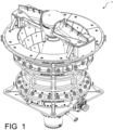
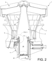
- a gyratory crusher 1 comprises a mainshaft assembly 2.
- the mainshaft assembly 2 comprises a mantle 7 (e.g., outer crushing surface liner), a lower mainshaft 26 adjacent its lower distal portion, and a lift hook 47 adjacent its upper proximal portion.
- mantle 7 e.g., outer crushing surface liner
- lower mainshaft 26 adjacent its lower distal portion
- lift hook 47 adjacent its upper proximal portion
- the gyratory crusher 1 may further comprise a mainframe which may include a lower top shell 3, a bottom shell 4, and a top shell 5, without limitation. Any two or more of the shell portions 3, 4, 5 may be made integral with each other, without limitation.
- a spider 6 may span a top opening as shown.
- a concave 8 (e.g., inner crushing surface liner) may protect the inner portions of the mainframe.
- the mainshaft assembly 2 may be received within a liner 12 of an eccentric 11.
- An annular dust bonnet 9 may be provided around the mainshaft assembly 2, and an annular dust seal 10 may be provided around an outer surface of the dust bonnet 9.
- a counterweight 13 may be affixed to an upper portion of eccentric 11 and/or eccentric liner 12.
- the counterweight 13 may comprise a non-annular arcuate shape (e.g., a "C" shape), as shown, without limitation.
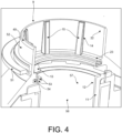
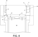
- the gyratory crusher 1 may differ from conventional gyratory crushers in that its dust bonnet 8 may comprise a number of guide mounts 14 provided to an inner sidewall 22 of the dust bonnet 9.
- the guide mounts 14 may extend at an angle between the inner sidewall 22 and a lower sidewall 23 of the dust bonnet 9 as shown.
- the lower sidewall 23 may extend radially inwardly (e.g., perpendicularly to the inner sidewall 22 when viewed in cross-section).
- the lower sidewall 23 may form a radially-inwardly extending shelf, lip, or flange, without limitation.
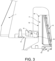
- an upper peripheral region of the dust bonnet 9 may comprise an upper radially-outer chamfer 49 which is configured with an angle which works in harmony with a lower radially-inner chamfer 50 of dust seal 10 provided within the mainshaft assembly 2 and held in place by dust seal cover 51.
- the upper radially-outer chamfer 49 on the dust bonnet 9 engages the lower radially-inner chamfer 50 of the dust seal 10.
- FIG. 3 shows a mainshaft assembly 2 position where the dust seal 10 has slid past the upper radially-outer chamfer 49 and past a majority of the outer peripheral surface 52 of the dust bonnet 9.
- the guide mounts 14 may be configured with an integrally-formed guide surface or, as shown, may be configured to receive one or more separable guides 15.
- Each guide 15 may comprise, for instance, a replaceable wear surface or liner, without limitation.
- Guides 15 may comprise a bearing material such as bronze or a polymer, without limitation.
- guide mounts 14 may each be provided with an inclined base surface 20, such as a ramp structure.
- the inclined base surface 20 may, itself, be a guide surface configured for and intended for sliding against an end plate 32 or other portion of mainshaft assembly 2 (e.g., an outer diameter or peripheral surface of lower mainshaft 26), without limitation.
- a replaceable/separable guide 15 may be affixed to the inclined base surface 20 using one or more fasteners 25 (e.g., machine screw, bolt), without limitation.
- fasteners 25 e.g., machine screw, bolt
- permanent or semi-permanent attachment methods e.g., brazing, welding, adhering
- one or more side rails 21 protruding from inclined base surface 20 may be provided on either or both sides of the guide(s) 15 as shown.
- the side rails 21 may project radially inwardly from guide mount 14 with respect to the dust bonnet 9, and may extend along guide mount 14 at an angle between inner 22 and lower 23 sidewalls.
- the side rails 21 may extend generally perpendicularly from the inclined base surface 20, without limitation.
- Each guide 15 may comprise one or more apertures 16 (e.g., one or more countersunk recesses) for receiving one or more respective fasteners 25 as depicted.
- An aperture 16 described herein may be sized and shaped to complimentarily receive a head of a fastener 25 as shown, and/or configured such that the fastener 25 does not protrude past an outer guide surface of a guide 15, without limitation.
- One or more side apertures 17 may be provided transversely to a separable or integral guide 15 as shown, and these may serve to receive one or more respective side pins 24 for temporarily or permanently securing a guide 15 to a guide mount 14, without limitation.
- Side pins 24 may extend entirely through guide mount 14, or partially into each guide 15 as shown.
- Side pins 24 may comprise roll pins, rollers, screws or other type of fastener which are pressed screwed into, or otherwise received through a side rail 21 and guide 15, without limitation.
- Guide mounts 14 may also comprise one or more side apertures 19 to receive the side pins 24 as shown, without limitation.
- side pins 24 may intersect apertures 16 so as to serve as set screws against fasteners 25, or other locking features without limitation.
- side pins 24 may extend through side rails 21.
- One or more mounting holes 18 may be provided to each guide mount 14 for receiving fasteners 25 (e.g., a fastener 25 extending through guide 15 and received within aperture 16).
- a distal portion of the mainshaft assembly 2 may be configured to rest on a thrust bearing 48, and the lower mainshaft 26 may be configured to be received within the lined eccentric 11.
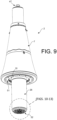
- the gyratory crusher 1 may differ from conventional gyratory crushers in that a lower mainshaft 26 of the mainshaft assembly 2 may comprise a specially-configured bottom plate 32.
- the lower mainshaft 26 may comprise a recess 46 ( FIG. 10 ) within its distal end as shown.
- the recess 46 may be defined, for example, by a bottom surface 29 surrounded by a lower annular projection 28, without limitation.
- the lower annular projection 28 may be continuous as shown; however, it may comprise interruptions (e.g., so as to be castellated or partially castellated, undulating, scalloped, or the like), without limitation.
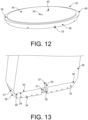
- the lower annular projection 28 may be configured to engage with and/or abut an upper annular lip 38 adjacent an upper side of the end plate 32 as suggested in FIG. 13 . Surfaces of the lower annular projection 28 may snugly abut complementary surfaces and/or geometric features of the lower annular projection 28, without limitation.
- the upper annular lip 38 of the end plate 32 may be defined around or surround an upper projection 45 which is configured to extend into recess 46 of the lower mainshaft 26, without limitation.
- the upper projection 45 may protrude upwardly from the upper annular lip 38 and may be arranged centrally and/or concentrically with respect thereto as shown.
- a lower side of the bottom plate 32 may comprise a number of radial oil grooves 33 and/or one or more annular oil grooves 34 may be provided on its bottom surface, without limitation.
- the grooves 33, 34 may assist with the holding and channeling of oil between the end plate 32 and thrust bearing 48 thereby facilitating lubrication.
- the radial oil grooves 33 may be interrupted along a radial line as shown, so as to form a plurality of staggered arcuate block projections 55.
- the staggered arcuate block projections 55 may form a circular tile mosaic pattern as illustrated.
- the radial 33 and annular 34 oil grooves may be interconnected such that they collectively form a tortuous path for oil to move, thereby improving upon the "rose" pattern shown in FIGS. 14-16 .
- a central pocket 35 may be provided to the lower side of the end plate 32 for receiving a fastener 30 for securing the end plate 32 to the lower mainshaft 26.
- a pattern of spaced pockets may be provided and arranged within end plate 32 in order to provide means for securing the end plate 32 to the lower mainshaft 26.
- the fastener 30 may comprise a bolt or threaded pin, without limitation.
- the fastener 30 may, as shown in FIG. 13 , be received through an opening or mounting hole 39 in the end plate 32 and threaded into, welded into, or otherwise mounted within a bore 37 of the lower mainshaft 26 without limitation.
- the bore 37 may be centrally located within recess defined by bottom surface 29 and lower annular projection 28.
- the fastener 30 may comprise a projection integral with the lower mainshaft 26 and machined into the lower mainshaft 26, without limitation.
- a fastening nut or bolt head 31 may be situated within the central pocket 35 of the end plate 32 so as to be clear from impingement with the thrust bearing 48 supporting the lower side of end plate 32.
- a lower alignment chamfer 36 (e.g., a frustoconical taper or lead-in surface).
- the lower alignment chamfer 36 may match the taper angle of an upper alignment chamfer 27 of the lower annular projection 28 as shown.
- a lower annular edge of the upper alignment chamfer 27 may abut or meet with an upper annular edge of the upper annular lip 38, as shown.
- Surfaces of the upper alignment chamfer 27 and lower alignment chamfer 36 may be flush with one another, collectively continuous, or generally follow the same outer chamfer taper angle - thereby creating a smooth homogeneous transition between lower mainshaft 26 and end plate 32.
- mating surfaces between upper annular lip 38 and lower annular projection 28 may be interlocking (e.g., undulating, scalloped, undulating), without limitation.
- the outer surface of upper projection 45 and inner surface of lower annular projection 28 can be complimentary splined surfaces, without limitation.
- rotation of end plate 32 with respect to lower mainshaft 26 may be discouraged or prevented by providing one or more alignment pins 44 to bottom surface 29 such that they protrude into respective alignment holes 40.
- upper projection 45 can be prevented from spinning within lower annular projection 28 during operation, which could cause loosening of fasteners 30, 31 attaching the end plate 32 to the lower mainshaft 26.
- FIGS. 14-16 show a conventional end plate (according to the prior art) of which end plate 32 aims to improve upon.
- a conventional end plate comprises a cylindrical body provided with a rose pattern of oil grooves at its lower surface.
- the outer peripheral cylindrical surface is radially-inwardly inset from other surfaces of a distal end of a lower mainshaft.
- FIGS. 17-19 another novel feature of the gyratory crusher 1 is the provision of an alignment chamfer 41 to a counterweight 13 which is intended for attaching to an upper portion of an eccentric 11 and/or liner 12 thereof.
- the counterweight may comprise a non-annular arcuate shape (e.g., a "C" shape), as shown, without limitation.
- the alignment chamfer 41 may, as shown, be provided to an inner concave portion of the counterweight, such that the counterweight 13 is generally narrower in width adjacent an upper part of the counterweight 13 and generally wider in width adjacent a lower part of the counterweight 13.
- a number of projections 42 may be provided to a lower face of the counterweight 13 ( FIG. 19 ). These projections 42 may serve as centering features, without limitation. As shown in FIG. 17 , the projections 42 may rest in a gap shelf between eccentric 11 and inner liner 12. Mounting holes 43 (which may be countersunk as shown) may be provided through counterweight 13. In some embodiments, such as the one shown, mounting holes 43 may extend into, disrupt, or intersect the alignment chamfer 41. Mounting holes 43 may also extend through projections 42, for example, to increase length of engagement between the fasteners and the mounting holes 43. The mounting holes 43 may enable fasteners (not shown) to pass through the counterweight and into a portion of the eccentric 11 and/or liner 12 to secure the counterweight 13 thereto.
- FIGS. 20-21 as the mainshaft assembly 2 is lowered into the gyratory crusher 1 during reintroduction or reassembly, guides 15 help "rough center” the lower mainshaft 26 into alignment with the oil seal(s) 52 and/or eccentric 11.
- the smooth lead-in taper collectively formed by the flush lower alignment chamfers 27, 36 presents itself to oil seal(s) 53 to more "finely align” the lower mainshaft 26 with the oil seal(s) 53 and/or eccentric 11.
- oil seal(s) 53 may be guided around outer peripheral surfaces (i.e., the outer diameter of) lower mainshaft 26.
- the smooth lead-in taper collectively formed by the flush lower alignment chamfers 27, 36 subsequently presents itself to the alignment chamfer 41 of counterweight 13.
- One or both of lower alignment chamfers 27, 36 may ride against surfaces of alignment chamfer 41 to supplementally finish guiding the lower mainshaft 26 into the eccentric 11 (e.g., into a liner 11 disposed therein), without limitation.
- Synergistic combinations of features 15, 27, 36, 41, 49, 50, disclosed herein may contribute to a greater self-aligning/self-centering effect.
- an eccentric liner 12 may be entirely optional.
- the eccentric liner 12 may be omitted from the eccentric 11 (wherein the bore 56 and/or inner diameter 57 may be formed directly through the body of eccentric 11).
- an eccentric liner 12 may be provided as an integral surface portion of eccentric 11.
- the eccentric liner 12 and eccentric 11 may be, in some embodiments, provided as a monolithic unitary structure and may be inseparable from each other, without limitation.
- the eccentric liner 12 and eccentric may also be provided as separable parts which have a clearance fit or press fit between them.
- bore 56 and “inside diameter” 57 may relate to an opening through an eccentric 11 or its liner 12 - whichever is smaller in diameter, configured to receive the lower mainshaft 26, and/or which comprises the bearing surfaces designed to abut, envelope, or constrain lateral movement of the outer peripheral diametrical surface of lower mainshaft 26, without limitation.
- guide 15 may refer to a separable guide structure that is removably affixed or mounted to a separate guide mount 14 as depicted in the figures; or, it may broadly refer to or encompass any structure connected to, integral with, attached to, or extending from the inner surface 22 of the dust bonnet 9 which is adequately configured to help concentrically align a lower mainshaft 26 of the mainshaft assembly 2 with one or more oil seals 53 and/or the inside diameter 57 of bore 56 of the eccentric 11 or its optional liner 12.
- guide 15 may also refer to or encompass any structure connected to, integral with, attached to, or extending from the inner surface 22 of the dust bonnet 9 which is adequately configured to help guide the lower mainshaft 26 into an oil seal(s) 53, eccentric 11, eccentric liner 12, bore 56, and/or inside diameter 57 when the mainshaft assembly 2 is lowered into the gyratory crusher 1, without limitation.
- a contractor or other entity may provide a gyratory crusher 1 or component(s) thereof as substantially shown and described herein, or, may practice any one or more of the methods or method steps shown and described herein, without limitation.
- a contractor or other entity may operate a gyratory crusher 1 as shown and described.
- a contractor or other entity may fabricate, provide, or install a gyratory crusher 1 as substantially shown and described herein, and this may include conversion of an existing gyratory crusher to provide a gyratory crusher 1 configured to improve mainshaft self-alignment during installation.
- a contractor or other entity may receive a bid request for a project related to designing, fabricating, delivering, installing, operating, or performing maintenance on a gyratory crusher, or, for providing a component thereof as substantially described herein, with the intention or purpose of converting an existing gyratory crusher to one incorporating the inventive features, concepts, and associated advantages described herein.
- a contractor or other entity may offer to design such a gyratory crusher 1 or component thereof, for a client.
- a contractor or other entity may subcontract or facilitate the fabrication, delivery, sale, and/or installation of any component(s) of the gyratory crusher disclosed.
- the contractor or other entity may also maintain, modify, retrofit, or upgrade a gyratory crusher (or one or more components thereof) in order to produce a gyratory crusher 1 as shown and described.
- the contractor or other entity may provide such maintenance or modifications by subcontracting such services or by directly providing those services or components needed for said maintenance, modifications, retrofit, or upgrades.
- the contractor or other entity may modify an existing gyratory crusher by virtue of provision of a retrofit kit to arrive at a modified gyratory crusher 1 comprising any number of the components described herein, or one or more of the inventive method steps, design features, devices, or inventive concepts discussed herein.
Landscapes
- Engineering & Computer Science (AREA)
- Mechanical Engineering (AREA)
- Food Science & Technology (AREA)
- Crushing And Grinding (AREA)
Applications Claiming Priority (3)
| Application Number | Priority Date | Filing Date | Title |
|---|---|---|---|
| US202063076056P | 2020-09-09 | 2020-09-09 | |
| PCT/IB2021/058227 WO2022053988A1 (en) | 2020-09-09 | 2021-09-09 | Gyratory crusher with self-aligning mainshaft features and method of assembly thereof |
| EP21770308.1A EP4210873B1 (de) | 2020-09-09 | 2021-09-09 | Kreiselbrecher mit selbstausrichtenden hauptwellenmerkmalen und verfahren zur montage davon |
Related Parent Applications (1)
| Application Number | Title | Priority Date | Filing Date |
|---|---|---|---|
| EP21770308.1A Division EP4210873B1 (de) | 2020-09-09 | 2021-09-09 | Kreiselbrecher mit selbstausrichtenden hauptwellenmerkmalen und verfahren zur montage davon |
Publications (2)
| Publication Number | Publication Date |
|---|---|
| EP4461409A2 true EP4461409A2 (de) | 2024-11-13 |
| EP4461409A3 EP4461409A3 (de) | 2025-01-29 |
Family
ID=77774949
Family Applications (2)
| Application Number | Title | Priority Date | Filing Date |
|---|---|---|---|
| EP24202284.6A Pending EP4461409A3 (de) | 2020-09-09 | 2021-09-09 | Kreiselbrecher mit selbstausrichtenden hauptwellenmerkmalen und verfahren zur montage davon |
| EP21770308.1A Active EP4210873B1 (de) | 2020-09-09 | 2021-09-09 | Kreiselbrecher mit selbstausrichtenden hauptwellenmerkmalen und verfahren zur montage davon |
Family Applications After (1)
| Application Number | Title | Priority Date | Filing Date |
|---|---|---|---|
| EP21770308.1A Active EP4210873B1 (de) | 2020-09-09 | 2021-09-09 | Kreiselbrecher mit selbstausrichtenden hauptwellenmerkmalen und verfahren zur montage davon |
Country Status (10)
| Country | Link |
|---|---|
| US (1) | US11850600B2 (de) |
| EP (2) | EP4461409A3 (de) |
| CN (2) | CN116323004B (de) |
| AU (2) | AU2021339095B2 (de) |
| CA (1) | CA3193616A1 (de) |
| CL (2) | CL2023000649A1 (de) |
| FI (1) | FI4210873T3 (de) |
| MX (1) | MX2023002794A (de) |
| PE (1) | PE20231284A1 (de) |
| WO (1) | WO2022053988A1 (de) |
Families Citing this family (1)
| Publication number | Priority date | Publication date | Assignee | Title |
|---|---|---|---|---|
| US12305761B2 (en) * | 2022-04-07 | 2025-05-20 | Metso Outotec USA Inc. | System and method of aligning a main shaft of a gyratory crusher |
Citations (3)
| Publication number | Priority date | Publication date | Assignee | Title |
|---|---|---|---|---|
| US4586664A (en) | 1983-04-01 | 1986-05-06 | Kabushiki Kaisha Kobe Seiko Sho | Bearing supporting system for cone crusher |
| US20120223171A1 (en) | 2009-09-15 | 2012-09-06 | Metso Minerals Industries, Inc. | Concentrated Bi-Density Eccentric Counterweight For Cone-Type Rock Crusher |
| US20140215788A1 (en) | 2012-12-04 | 2014-08-07 | Flsmidth A/S | Method for assembling a crusher |
Family Cites Families (18)
| Publication number | Priority date | Publication date | Assignee | Title |
|---|---|---|---|---|
| US2147833A (en) * | 1934-05-07 | 1939-02-21 | Arthur W Fahrenwald | Crushing mill |
| US2135324A (en) * | 1936-01-04 | 1938-11-01 | Brown Peter Boswell | Gyratory crushing machine |
| US4454994A (en) * | 1982-02-04 | 1984-06-19 | Johnson Louis W | Load bearing surface |
| US4919349A (en) * | 1989-10-10 | 1990-04-24 | Johnson Louis W | Dust seal for gyratory rock crushers |
| AUPM985594A0 (en) * | 1994-12-02 | 1995-01-05 | Ledger Engineering Pty Ltd | Improved gyratory crusher |
| US5718390A (en) * | 1996-03-18 | 1998-02-17 | Cedarapids, Inc. | Gyratory crusher |
| US6550707B2 (en) * | 2001-01-05 | 2003-04-22 | Sandvik Ab | Gyratory crusher dust seal system |
| CN201168616Y (zh) * | 2007-11-12 | 2008-12-24 | 王鹏 | 单缸液压式圆锥破碎机 |
| US8033491B2 (en) * | 2008-05-22 | 2011-10-11 | Flsmidth A/S | Top service gyratory crusher |
| SE535215C2 (sv) * | 2010-07-09 | 2012-05-22 | Sandvik Intellectual Property | Gyratorisk kross med tätningsanordning, samt förfarande för att skydda en arbetszon |
| KR101191267B1 (ko) * | 2011-04-14 | 2012-10-16 | 하용간 | 콘형 크러셔 |
| EP2689850B1 (de) * | 2012-07-27 | 2017-11-15 | Sandvik Intellectual Property AB | Kreiselbrecher und gleitlagerbuchse |
| EP2774682B1 (de) * | 2013-03-08 | 2015-12-30 | Sandvik Intellectual Property AB | Montageanordnung für die Hauptwelle eines Kreiselbrechers |
| CN203264772U (zh) * | 2013-05-28 | 2013-11-06 | 成都大宏立机器股份有限公司 | 一种惯性圆锥破碎机偏心配重结构 |
| CN204396063U (zh) * | 2014-12-26 | 2015-06-17 | 浙江浙矿重工股份有限公司 | 一种圆锥破碎机用凹凸面下一体式止推机构 |
| AU2016396736A1 (en) * | 2016-03-07 | 2018-08-23 | Sandvik Intellectual Property Ab | Sealing assembly for gyratory crusher |
| US11143306B1 (en) * | 2017-01-23 | 2021-10-12 | Tristar Design and Manufacturing, Inc. | Self-aligning seal |
| US11148146B2 (en) * | 2019-03-25 | 2021-10-19 | Metso Outotec Finland Oy | Cone crusher |
-
2021
- 2021-09-09 CA CA3193616A patent/CA3193616A1/en active Pending
- 2021-09-09 FI FIEP21770308.1T patent/FI4210873T3/fi active
- 2021-09-09 CN CN202180069068.3A patent/CN116323004B/zh active Active
- 2021-09-09 CN CN202511550975.6A patent/CN121372563A/zh active Pending
- 2021-09-09 US US18/025,569 patent/US11850600B2/en active Active
- 2021-09-09 AU AU2021339095A patent/AU2021339095B2/en active Active
- 2021-09-09 EP EP24202284.6A patent/EP4461409A3/de active Pending
- 2021-09-09 MX MX2023002794A patent/MX2023002794A/es unknown
- 2021-09-09 PE PE2023001008A patent/PE20231284A1/es unknown
- 2021-09-09 EP EP21770308.1A patent/EP4210873B1/de active Active
- 2021-09-09 WO PCT/IB2021/058227 patent/WO2022053988A1/en not_active Ceased
-
2023
- 2023-03-07 CL CL2023000649A patent/CL2023000649A1/es unknown
-
2024
- 2024-08-23 AU AU2024216305A patent/AU2024216305B2/en active Active
-
2025
- 2025-04-21 CL CL2025001181A patent/CL2025001181A1/es unknown
Patent Citations (3)
| Publication number | Priority date | Publication date | Assignee | Title |
|---|---|---|---|---|
| US4586664A (en) | 1983-04-01 | 1986-05-06 | Kabushiki Kaisha Kobe Seiko Sho | Bearing supporting system for cone crusher |
| US20120223171A1 (en) | 2009-09-15 | 2012-09-06 | Metso Minerals Industries, Inc. | Concentrated Bi-Density Eccentric Counterweight For Cone-Type Rock Crusher |
| US20140215788A1 (en) | 2012-12-04 | 2014-08-07 | Flsmidth A/S | Method for assembling a crusher |
Also Published As
| Publication number | Publication date |
|---|---|
| AU2021339095B2 (en) | 2024-05-23 |
| CN116323004B (zh) | 2025-11-14 |
| AU2024216305A1 (en) | 2024-09-12 |
| AU2024216305B2 (en) | 2026-04-23 |
| US11850600B2 (en) | 2023-12-26 |
| CN116323004A (zh) | 2023-06-23 |
| US20230330681A1 (en) | 2023-10-19 |
| CL2023000649A1 (es) | 2023-08-25 |
| EP4210873A1 (de) | 2023-07-19 |
| EP4461409A3 (de) | 2025-01-29 |
| WO2022053988A1 (en) | 2022-03-17 |
| MX2023002794A (es) | 2023-03-16 |
| PE20231284A1 (es) | 2023-08-22 |
| FI4210873T3 (fi) | 2024-11-04 |
| EP4210873B1 (de) | 2024-10-02 |
| CN121372563A (zh) | 2026-01-23 |
| CL2025001181A1 (es) | 2025-08-18 |
| CA3193616A1 (en) | 2022-03-17 |
| AU2021339095A1 (en) | 2023-04-06 |
Similar Documents
| Publication | Publication Date | Title |
|---|---|---|
| US8033491B2 (en) | Top service gyratory crusher | |
| US8042756B2 (en) | Vertical shaft impact crusher | |
| AU2024216305B2 (en) | Gyratory crusher with self-aligning features | |
| US8414258B2 (en) | Support bar for turbine diaphragm that facilitates reduced maintenance cycle time and cost | |
| US20240040968A1 (en) | Grinding mill liner | |
| WO2015051980A1 (en) | Gyratory crusher spider arm shields | |
| US20240299947A1 (en) | Gyratory crusher with self-aligning mainshaft features and method of assembly thereof | |
| US4378911A (en) | Cage mill | |
| US20110101142A1 (en) | Distributor plate locking mechanism for vertical shaft impact crusher | |
| RU2739464C2 (ru) | Узел втулки крестовины для гирационной дробилки | |
| TWI626086B (zh) | 一種用於精磨機和分散機的簡化質量板及其製造方法 | |
| US6390401B1 (en) | Liner segment locator/retainer for ORE grinding mills | |
| CN109311020B (zh) | 轴承筒和立轴冲击式破碎机 | |
| US8911152B2 (en) | Bearing | |
| CA3070651C (en) | Pressure plate apparatus | |
| EA048882B1 (ru) | Конусная дробилка с самоцентрирующимися элементами главного вала и ее пылезащитный кожух | |
| US20250108387A1 (en) | Segmented Screen Assembly for Cuttings Dryer | |
| US4477031A (en) | Apparatus for ready conversion of crushing cavity configuration in a cone crusher | |
| CN111655377B (zh) | 带有检查舱口组件的回转破碎机底壳 | |
| CN216910470U (zh) | 一种重型大负载耐冲击双转子锤式萤石破碎机 | |
| EP3854481A1 (de) | Druckplattenvorrichtung | |
| WO2026047278A1 (en) | Upper head bushing | |
| CA1159425A (en) | Apparatus for ready conversion of crushing cavity configuration in a cone crusher | |
| EA045938B1 (ru) | Лифтерный стержень, устройство для выгрузки измельченного материала, расположенное на разгрузочном конце мельницы, и способ демонтажа разгрузочного конца мельницы | |
| WO2000064587A1 (en) | Pulverising mill |
Legal Events
| Date | Code | Title | Description |
|---|---|---|---|
| PUAI | Public reference made under article 153(3) epc to a published international application that has entered the european phase |
Free format text: ORIGINAL CODE: 0009012 |
|
| STAA | Information on the status of an ep patent application or granted ep patent |
Free format text: STATUS: THE APPLICATION HAS BEEN PUBLISHED |
|
| AC | Divisional application: reference to earlier application |
Ref document number: 4210873 Country of ref document: EP Kind code of ref document: P |
|
| AK | Designated contracting states |
Kind code of ref document: A2 Designated state(s): AL AT BE BG CH CY CZ DE DK EE ES FI FR GB GR HR HU IE IS IT LI LT LU LV MC MK MT NL NO PL PT RO RS SE SI SK SM TR |
|
| REG | Reference to a national code |
Ref country code: DE Ref legal event code: R079 Free format text: PREVIOUS MAIN CLASS: B02C0002000000 Ipc: B02C0002020000 |
|
| PUAL | Search report despatched |
Free format text: ORIGINAL CODE: 0009013 |
|
| AK | Designated contracting states |
Kind code of ref document: A3 Designated state(s): AL AT BE BG CH CY CZ DE DK EE ES FI FR GB GR HR HU IE IS IT LI LT LU LV MC MK MT NL NO PL PT RO RS SE SI SK SM TR |
|
| RIC1 | Information provided on ipc code assigned before grant |
Ipc: B02C 2/00 20060101ALI20241223BHEP Ipc: B02C 2/04 20060101ALI20241223BHEP Ipc: B02C 2/02 20060101AFI20241223BHEP |
|
| STAA | Information on the status of an ep patent application or granted ep patent |
Free format text: STATUS: REQUEST FOR EXAMINATION WAS MADE |
|
| 17P | Request for examination filed |
Effective date: 20250523 |