EP4461896A1 - Eléments de construction modulaires - Google Patents
Eléments de construction modulaires Download PDFInfo
- Publication number
- EP4461896A1 EP4461896A1 EP24174701.3A EP24174701A EP4461896A1 EP 4461896 A1 EP4461896 A1 EP 4461896A1 EP 24174701 A EP24174701 A EP 24174701A EP 4461896 A1 EP4461896 A1 EP 4461896A1
- Authority
- EP
- European Patent Office
- Prior art keywords
- building element
- ceiling
- floor
- building
- joists
- Prior art date
- Legal status (The legal status is an assumption and is not a legal conclusion. Google has not performed a legal analysis and makes no representation as to the accuracy of the status listed.)
- Pending
Links
Images








Classifications
-
- E—FIXED CONSTRUCTIONS
- E04—BUILDING
- E04B—GENERAL BUILDING CONSTRUCTIONS; WALLS, e.g. PARTITIONS; ROOFS; FLOORS; CEILINGS; INSULATION OR OTHER PROTECTION OF BUILDINGS
- E04B1/00—Constructions in general; Structures which are not restricted either to walls, e.g. partitions, or floors or ceilings or roofs
- E04B1/348—Structures composed of units comprising at least considerable parts of two sides of a room, e.g. box-like or cell-like units closed or in skeleton form
- E04B1/34815—Elements not integrated in a skeleton
- E04B1/34838—Elements not integrated in a skeleton the supporting structure consisting of wood
-
- E—FIXED CONSTRUCTIONS
- E04—BUILDING
- E04B—GENERAL BUILDING CONSTRUCTIONS; WALLS, e.g. PARTITIONS; ROOFS; FLOORS; CEILINGS; INSULATION OR OTHER PROTECTION OF BUILDINGS
- E04B1/00—Constructions in general; Structures which are not restricted either to walls, e.g. partitions, or floors or ceilings or roofs
- E04B1/18—Structures comprising elongated load-supporting parts, e.g. columns, girders, skeletons
- E04B1/26—Structures comprising elongated load-supporting parts, e.g. columns, girders, skeletons the supporting parts consisting of wood
- E04B1/2604—Connections specially adapted therefor
- E04B1/2612—Joist hangers
-
- E—FIXED CONSTRUCTIONS
- E04—BUILDING
- E04B—GENERAL BUILDING CONSTRUCTIONS; WALLS, e.g. PARTITIONS; ROOFS; FLOORS; CEILINGS; INSULATION OR OTHER PROTECTION OF BUILDINGS
- E04B1/00—Constructions in general; Structures which are not restricted either to walls, e.g. partitions, or floors or ceilings or roofs
- E04B1/62—Insulation or other protection; Elements or use of specified material therefor
- E04B1/74—Heat, sound or noise insulation, absorption, or reflection; Other building methods affording favourable thermal or acoustical conditions, e.g. accumulating of heat within walls
- E04B1/82—Heat, sound or noise insulation, absorption, or reflection; Other building methods affording favourable thermal or acoustical conditions, e.g. accumulating of heat within walls specifically with respect to sound only
- E04B2001/8254—Soundproof supporting of building elements, e.g. stairs, floor slabs or beams, on a structure
Definitions
- the technology of the present disclosure relates to the field of modular building elements comprising wood and/or steel.
- EP2241692A2 discloses a house module, an assembly of a number of house modules for forming a house, a house comprising a number of house modules and to a method for manufacturing a house.
- it is proposed to form a house from concrete house modules. A number of concrete house modules are manufactured centrally and subsequently transported to a building site.
- the present disclosure contemplates improving the process of constructing a building formed by multiple modular building elements.
- the present disclosure contemplates using at least in part different materials, such as but not limited to wood, wood-derived products, plastics, composite materials, metals such as steel or aluminium, or any combination thereof. Although different materials are used, the technology of the present disclosure still provides for an efficient building process.
- Improvements may be found in terms of speed in which the modular building elements can be formed and/or in which the building can be constructed, in reducing weight and/or material use, and/or in reducing an environmental footprint of the building formed from the modular elements.
- the present disclosure contemplates in a first aspect a modular building formed by at least a bottom modular building element and a top modular building element.
- the top building element is positioned above the bottom building element.
- the bottom building element comprises a floor, a ceiling with one or more ceiling joists connected to at least one transverse ceiling beam, and one or more columns coupling the floor and the ceiling
- the top building element comprises a floor with one or more floor joists connected to at least one transverse floor beam, a ceiling, and one or more columns coupling the floor and the ceiling
- the one or more ceiling joists of the bottom building element and the one or more floor joists of the top building element are positioned substantially parallel and at least partially side-by-side.
- the bottom building element comprises a floor, a ceiling with multiple ceiling joists connected between two transverse ceiling beams, and one or more columns coupling the floor and the ceiling.
- the top building element comprises a floor with multiple floor joists connected between two transverse floor beams, a ceiling, and one or more columns coupling the floor and the ceiling.
- the ceiling joists and the floor joists are positioned substantially parallel and at least partially side-by-side, and at least the ceiling joists and the floor joists are formed from wood, wood derived product, or metal.
- the ceiling joists and the floor joists being positioned substantially parallel and at least partially side-by-side, a more compact building can be obtained.
- the ceiling joists and floor joists may thus form a staggered arrangement relative to each other.
- wood, wood derived product, plastic, fibrous material, and/or metal may allow for a lighter and/or more environmentally friendly design - compared to modules comprising concrete, in particular when a majority of the module is formed from concrete, for example reinforced concrete.
- wood-derived products are CLT (cross laminated timber), OSB (oriented strand board), plywood, glue-laminated-timber and laminated veneer lumber.
- metals are steel and aluminum.
- a plastic can be any polymer, optionally as a fibre-reinforced composite material.
- fibrous materials are paper, cardboard, felt, mineral wool, or any material comprising fibres, for example cellulose fibres.
- one or more columns may be used to couple the floor and the ceiling of a modular building element.
- To couple here implies that forces can be transferred between the floor and the ceiling via the columns.
- the columns of the bottom building element may supported on a foundation of the modular building.
- one or more vertical wall elements may be used to couple the floor and the ceiling of any modular building element disclosed herein.
- the majority of vertical forces are transferred via columns and/or wall elements.
- the majority or even all of the weight of the top building element is supported on the column of the bottom building element.
- the use of columns may prevent or reduce a need of contact between other components of the top building element and the bottom building element. Such contact may otherwise result in undesired transfer of sound between the building elements.
- a column may have any cross-section shape and size.
- a column may be sized such that it form part of a wall of the building element. As such, a column may span between 0.5% and 99.5% of a width and/or length of a building element.
- a column may be widened in such a way that one horizontal dimension of a column is larger than the other, for example at least two times or four times wider, so that it forms a wide column, or a slab.
- a wide column may be beneficial to stabilize the building element.
- a modular building element can be a bottom modular building element, a top modular building element, or even a bottom and top modular building element at the same time.
- a modular building element above which another modular building element is positioned is generally regarded a bottom building element.
- a modular building element below which another modular building element is positioned is generally regarded a top building element.
- a modular building element above and below which another modular building element is positioned is generally regarded a bottom building element as well as a top modular element.
- a top modular building element which is the top most building element of a modular building may have any ceiling, for example with a ceiling beam arrangement which is similar to a floor, because it does not need to be able to have another element stacked on top of it.
- the ceiling joists of the bottom building element are shorter in length than the floor joists of the top building element, it may be achieved that at least part of the transverse floor beams of the top building element can be positioned at the same height as the ceiling joists of the bottom building element. This in turn may result in a more compact modular building.
- ceiling joists and floor joists as used herein can refer to a plurality of respectively ceiling joists and floor joists, or to a single respective ceiling joist and floor joist when a building element comprises respective only a single ceiling joist and floor joist.
- the ceiling joists of the bottom building element are shorter in length than a spacing between the two transverse floor beams of the top building element, at least part of the ceiling joists of the bottom building element can be positioned between the two transverse floor beams of the top building element. This in turn may result in a more compact modular building.
- transverse ceiling beams of the bottom building element are vertically structurally spaced apart from the transverse floor beams of the top building element, such that no substantial part of the weight of the top building element is transferred from the transverse floor beams of the top building element to the transverse ceiling beams of the bottom building element, transfer of sound between the bottom building element and the top building element may be reduced.
- a sound damping element is more sound damping compared to non-sound damping elements which may for example comprise concrete, wood, or steel.
- the sound damping element typically comprises or consists of material or materials with a lower E-modulus than wood and/or steel.
- a column interface element may be positioned between a first column of the bottom building element and a first column of the top building element, and wherein the weight of the top building element of the first column of the top building element is essentially transferred via the column interface element to the first column of the bottom building element.
- any column interface element may be connected to the first column of the bottom building element or to the first column of the top building element during assembly of the modular building.
- at least part of any column interface element may be formed by the first column of the bottom building element or to the first column of the top building element.
- the column interface element does not protrude beyond at least one of the first column of the bottom building element and the first column of the top building element in any horizontal direction.
- each set of columns comprising a column of the bottom building element and a column of the top element positioned above the column of the bottom building element in the respective set of columns.
- the column interface element may comprise at least two bodies, a first of the bodies comprising a male mating part and a second of the bodies comprising a female mating part which is at least partially shaped complementary to male mating part.
- a first of the bodies comprising a male mating part
- a second of the bodies comprising a female mating part which is at least partially shaped complementary to male mating part.
- Any of the male mating part and the female mating part may be formed by a column interface element, or conceivably also by a column.
- the complementary shape of the male and female mating part allows for convenient centering of two columns when stacked on top of each other.
- any column interface element may comprise or consist of wood, wood-derived product, metal, and/or plastic. Additionally or alternatively, any column interface element may comprise or consist of material with a low sound transmissivity.
- mounting brackets may be used to connect the ends of the ceiling joists to the transverse ceiling beams.
- the mounting brackets are more compact design of the modular building may be achieved.
- Any mounting bracket may additionally or alternatively prevent or reduce a chance of lateral torsional buckling of the ceiling joists, for example by limiting a sideways movement and rotation of the ceiling joists with respect to the transverse ceiling beams.
- the resistance to lateral torsional buckling of a ceiling joist may be increased.
- Any mounting bracket may be supported on a top surface of one of the transverse ceiling beams. Additionally or alternatively, at least one mounting bracket may be partially positioned along a side surface of one of the transverse ceiling beams.
- part of a top surface of at least one of the transverse ceiling beams of the bottom building element may extend into the building beyond an inner side surface of the transverse floor beam, and at least one of the ceiling joists of the bottom building element may be supported on the part of the top surface.
- At least one of the transverse ceiling beams of the bottom building element may be wider than at least one of the transverse floor beams of the top building element.
- a chance of lateral torsional buckling of said ceiling joist may be reduced.
- any ceiling joist may form a structural element with a hollow cross-section together with part of a ceiling surface of the bottom building element.
- the ceiling surface may for example be a gypsum plate, or comprise or consist of any other material such as timber, timber based material, fibrous material, mineral material, plastic material, any other suitable material, or any combination thereof.
- the ceiling joist itself, or the ceiling joist and the part of the ceiling surface preferably form a closed circumference.
- a bottom plane of at least one of the ceiling joists of the bottom modular element may be aligned with a top plane of the transverse ceiling beams.
- the present disclosure provides an alternative modular building.
- the modular building comprises a bottom modular building element and a top modular building element, the top building element being positioned above the bottom building element.
- Features disclosed in conjunction with the building elements in accordance with the building of the first aspect are readily applicable to building elements of the modular building according to the second aspect. These features for example relate to material use, dimensions of any beam, joist, positioning of beams, positioning of joists, options for interface elements, and any other feature disclosed herein.
- At least one ceiling joist of a bottom building element discussed in conjunction with a modular building according to the one of the first or second aspect is positioned substantially parallel and at least partially side-by-side with at least one floor joist of a top building element discussed in conjunction with a modular building according to the other of the first and second aspect.
- the bottom building element in the alternative modular building of the second aspect comprises a floor, and a ceiling with at least one ceiling joist.
- a ceiling with at least one ceiling joist.
- Any wall element is generally positioned vertically or approximately vertically, and can as such be referred to as a vertical wall element.
- the top building element in the alternative modular building of the second aspect comprises a floor with at least one floor joist, a ceiling, and one or more wall elements coupling the floor and the ceiling.
- at least one floor joist is positioned at least partially alongside the at least one wall element.
- the ceiling joists and the floor joists are positioned substantially parallel and at least partially side-by-side.
- at least the ceiling joists and the floor joists are formed from wood, wood derived product, plastic, fibrous material, and/or metal.
- columns are used to couple the floor and ceiling of the building elements
- one or more wall elements are used to couple the floor and the ceiling, at least for the top building element.
- a wall element generally covers an entire side, front, or rear of a building element, whereas when columns are used, typically two or more columns are positioned on one side, front or rear of the building element, with at least a small spacing between adjacent columns.
- a building element comprises a wall element
- the wall element may be used to substitute the transverse ceiling beam and/or transverse floor beam on one side of the building element.
- floor joists may extend between two wall elements.
- ceiling joists of a bottom modular element may be positioned for at least part of their height between wall elements of the top modular element.
- a bottom surface of a wall element may be essentially aligned with a bottom surface of one or more or all of the floor joists.
- a bottom surface of one or more or all of the ceiling joists may be essentially aligned with a top surface of a wall element.
- a wall element has a generally constant thickness. Any wall elements may have one or more openings therein, for example forming an opening for a window, door, or forming a passageway through the wall element. However, generally speaking, in a wall element with one or more openings, at least two vertical sections and two horizontal sections can be identified, which sections can overlap each other for example at the corners.
- one or more recesses may be formed in an inner side surface of the wall element.
- an end of a ceiling joist of a bottom building element may be positioned in the recess.
- Multiple independent recesses may be formed for example according to the number of ceiling joists om the bottom building element.
- the wall elements described herein are generally used to be load-bearing. In a stack of building elements comprising wall elements, vertical loads from the top building elements may be essentially carried by wall elements of bottom building elements.
- an interface element may be positioned at or near each of the four corners of the bottom building element, on which interface elements the weight of the top building element can be supported.
- a support on multiple interface elements instead of a direct support of the wall elements onto each other, may decrease transmission of sounds between the top building element and the bottom building element.
- the spacing is preferably filled with air or sound-dampening material. It is preferably avoided that the space between adjacent interface elements is filled with material through which weight from the top building element is transferred to the bottom building element, for example any wooden or metal materials.
- Modular buildings may be formed by combining one or more top elements and bottom elements from the modular buildings of the first and second aspects.
- a set of columns and associated transverse floor beam and/or transverse ceiling beam may be substituted by a wall element, and vice versa.
- the building elements used to form any modular building are regarded as separate aspects of the present disclosure.
- a top building element for use in a modular building and a bottom building element for use in a modular building are envisioned as separate aspects.
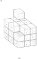
- Fig. 1 in a schematic isometric view shows a first example of a modular building 100 formed with modular building elements 32.
- Fig. 1 shows that it is envisioned that any modular building 100 may comprise a number of modular building elements in vertical direction, as well as in two orthogonal horizontal directions.
- Fig. 1 one of the top building elements '32 is shown in an exploded view, lifted away from a bottom building element.
- building elements will be positioned alongside each other and/or on top of each other.
- the building 100 comprises nine building elements, the building 100 being three elements wide, three elements long, and three elements high. Any building 100 disclosed herein may have a width, length, and height of one or more building elements.
- the building elements comprise columns, and weight of top building elements is transferred to columns of bottom building elements, a high number of building elements may be stacked on top of each other.
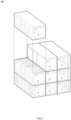
- Fig. 2 shows a second example of a modular building 100, with as an example twelve modular building elements 33.
- the modular building element are longer relative to the building 100.
- the building elements 33 have as an example a facade element on each side of the element.
- the building elements 33 are arranged with their longitudinal direction perpendicular to the facade of the building. the depth of the building 100 is thereby determined by the depth of the building element 33.
- Each element may have more than four columns, to allow an increase in the longitudinal direction, for example independent of the span of the floor joists and/or ceiling joists
- the facade elements do not have to be part of the building elements 33 and can also be connected after the building elements have been stacked on top of each other.
- Fig. 3 shows a third example of a modular building 100, shown as an example comprising nine building elements 34.
- the longitudinal direction of the elements 34 is parallel to the facade of the building 100.
- Fig. 3 depicts the general option that the ceiling of the top building elements '34 can be different from the ceiling of the bottom building elements 34.
- said ceiling can be a roof.
- a single modular building may comprise building elements which all have the same dimensions, or a single modular building may comprise building elements with different dimensions.
- a single building element may form a separate room, tenable space, office room or dwelling or a number of these spaces.
- a number of adjacent building elements may form a separate room, tenable space, office room or dwelling.
- one or more side walls of adjacent building element may be open to allow the adjacent building elements to together form an open space.
- FIGs. 1-3 building element comprising columns are depicted, any and all building elements may be substitute by building elements comprising one or more wall elements, as for example discussed in conjunction with Figs. 17-19B .
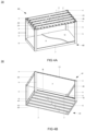
- Figs. 4A and 4B depict an example of a modular building element 30, which, when used to form part of a modular building together with at least one further building element, can be a top building element and/or bottom building element.
- multiple modular building elements 30 according to the example of Figs. 4A and 4B may be stacked on top of each other to form at least part of a modular building.
- the modular building element 30 is respectively depicted in an isometric top view, and an isometric bottom view, in Figs. 4A and 4B .
- the modular building element 30 comprises a floor 40, a ceiling 42, and a plurality of columns 5 coupling the floor 40 and the ceiling 42.
- Figs. 4A and 4B show four columns 5, it will be appreciated that as with any other modular building element disclosed herein, the modular building element 30 may comprise less than four columns, or more than four columns, for example five, six, eight or even more.
- the floor 40 depicted in Figs. 4A and 4B can generally be comprised by any modular building element disclosed herein, also the modular building element 300 of Fig. 17 .
- the floor 40 comprises a plurality of essentially parallel floor joists 9 connected between transverse floor beams 6.
- any floor may comprise any number of floor joists, including none or only one.
- the plurality of floor joists comprises two floor edge joists 7 generally disposed on opposite sides of the floor.
- the floor 40 further comprises a floor surface 8 and a floor finishing 10, both of which are optional for any floor disclosed herein.
- the floor joists 9 are typically formed each by a single beam-shaped element, and can be connected to the transverse floor beams 6 at opposite ends of the floor joists 9, or in case of the floor edge joists 7, the floor joists 7 can be connected to columns 5 at opposite ends of the floor joists 7.
- the ceiling 42 depicted in Figs. 4A and 4B can generally be comprised by any modular building element disclosed herein, in particular by any bottom building element, also the modular building element 300 of Fig. 17 .
- any other type of ceiling may be used, for example any conventional ceiling or roof element.
- the roof could in this case also be angled so that it is not parallel to the floors.
- the ceiling 42 comprises a number of ceiling joists 1 which are connected between two transverse ceiling beams 3.
- the transverse ceiling beams 3 are at least partially positioned below the ceiling joists 1 of the same building element.
- Any ceiling beam can comprise or consist of wood, wood-derived product, and/or a metal such as steel.
- the transverse ceiling beams are depicted with a rectangular cross-section, any transverse ceiling beam can have any other cross-sectional shape, for example a delta shaped, a C-shaped or an I-shaped cross-sectional shape.
- the ceiling 42 comprises a number of ceiling battens 11 and a ceiling surface 2 connected to the ceiling battens 11.
- a ceiling surface 2 may be connected directly to the ceiling joists.
- any ceiling joist can have a height between 150-400mm and a width between 30-200 mm.
- the ceiling surface 2 can be made from a gypsum based material (sheetrock or gypsum fibre board) or an alternative mineral composite material such as cement based or loam-based materials, timber based materials, fibrous material, plastic material, or any other suitable material, or any combination thereof.
- At least the ceiling joists and the floor joists, and preferably but necessarily also the columns, transverse ceiling beams, and/or transverse floor beams are formed from or at least comprise wood, wood derived product, metal, a composite material, a plastic, or any combination thereof.
- one, more, or all ceiling joists, floor joists, columns, transverse ceiling beams, transverse floor beams are not formed from concrete, in any combination thereof. This applies for any building element disclosed herein, in any combination of the different options.
- any one or more of the side faces may be at least partially closed, for example by a facade element, partition wall, party wall, or any other covering member.
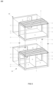
- Fig. 5 shows an exploded view of a modular building 100 - or at least part thereof.
- the modular building 100 comprises a top modular building element '30 and a bottom modular building element 30.
- a column interface elements 4 is typically positioned between two columns 5.
- the task of the column interface element is to provide a spacing between the bottom building element and the top building element, preferably to prevent any part of the of the bottom building element and top building - besides the column interface elements - from contacting in such a way that sound can be transmitted between the building elements at noticeable levels to people occupying the building elements.
- the column interface elements 4 are depicted as separate elements - separate from the columns 5. This is an option which can apply to any column interface element 4 disclosed herein. Any column interface element 4 may be formed by a single body, or may be formed by multiple separate bodies. When a column interface element 4 is formed by multiple separate bodies, the multiple separate bodies may be connected to multiple columns prior to assembly of the modular building. The same applies to the interface elements 400 discussed in conjunction with Figs. 17-19B . Also any other feature disclosed in conjunction with column interface elements can be readily applied to the interface elements 400 discussed in conjunction with Figs. 17-19B , in any combination.
- a column interface element is used to structurally couple two columns which are positioned one above the other.
- To structurally couple implies that the weight of the top column is transferred to the bottom column via the column interface element.
- any column interface element 4 does not protrude beyond their respective column 5 of the bottom building element and column 5 of the top building element in any horizontal direction.
- the column interface element 4 preferably does not extend beyond the footprint of the respective columns 5 of the bottom building element and/or top building element.
- Figs. 8A-8C three different column interfaces are depicted. It will be understood that any of the three column interfaces may be readily applied to any set of columns disclosed herein for any embodiment of the modular building. Other interfaces between a column 5' of a top building element and a column 5 of a bottom building element may also be used instead of the three particular interfaces depicted in Figs. 8A-8C .
- the column interface element is formed by two separate bodies 4' and 4".
- the first body 4' is connected to the bottom column 5, or may be formed by the bottom column 5 itself.
- the second body 4" is connected to the top column 5', or may be formed by the top column 5' itself.
- a first of the bodies comprises a male mating part 74
- a second of the bodies comprises a female mating part 75 which has a shape generally corresponding to at least part of the male mating part 74.
- the bodies 4' and 4" may be self-centering when the top column 5' is positioned on top of the bottom column 5.
- the body 4" associated with the top column 5' comprises the male mating part 74
- the body 4' associated with the bottom column 5 comprises the male mating part 74.
- the interface element 4 is formed as a vertical spacer 4. Furthermore, respectively the top column 5' and the bottom column 5 are provided with a protrusion 120 arranged to be at least partially positioned in a pocket 122 in respectively the bottom column 5 and the top column 5'. Preferably, but not necessarily, at least a distal end of the protrusion 120 is tapered towards the end, for example to facilitate inserting the protrusion 120 into the pocket 122.
- a depth of the pocket 122 may be larger, equal to, or smaller than a length of the protrusion 120, for example whether it is desired that weight is transferred through the protrusion 120 or the protrusion 120 is primarily used as a guiding tool for positioning one column above the other during assembly of the building.
- the column interface element 4 may be readily used as interface element 400 in conjunction with any modular building element, for example as discussed in conjunction with Figs. 17-19B .
- a partition wall 18 is positioned in the bottom building element 30.
- the partition wall 18 is oriented perpendicular to the ceiling joists 1, although it is also envisioned that any partition wall 18 can also be oriented parallel to the ceiling joists 1 or at any angle relative to the ceiling joists.
- FIG. 5 A further option depicted in Fig. 5 is that one or more sides of any building element disclosed herein may be covered with a facade element 16, with no, one, or more windows 17 of any shape and size in the facade element 16.
- the facade elements 16 in Fig. 5 are shown in an exploded view relative to the building elements 30 '30.
- the facade elements can for example either be already mounted to each module at the factory, or attached the modules on-site after the modules have been stacked.
- one or more transverse floor beams 6 of the building element may be positioned between two columns 5.
- any transverse floor beams 6 may be connected to a respective column 5, directly or indirectly through one or more connection elements.
- a top surface of the transverse floor beams is aligned with a top surface of the floor joists 7, 9.
- floor edge joists 7 may be positioned between two columns 5. For example, at the ends thereof, any floor edge joist 7 may be connected to a respective column 5, directly or indirectly through one or more connection elements. Typically, the floor edge joists 7 are shorter than the other floor joists 9.
- a bottom surface 40 of the columns 5 is aligned with, slightly above or below a bottom surface 44 of the transverse floor beams 6 and/or a bottom surface 45 of the floor edge joists 7.
- the bottom surface 40 of the columns 5 is at least positioned below a top surface of the transverse floor beams 6 and/or a top surface of the floor edge joists 7, in use.
- Fig. 6 shows a schematic exploded section view of the modular building 100 of Fig. 5 , along plane AA indicated in Fig. 7 . with the top building element '30 and the bottom building element 30.
- Fig. 7 shows a shows a schematic exploded section view of the modular building 100 of Fig. 5 cut along plane BB, with the top building element '30 and the bottom building element 30.
- the column interface elements 4 may be connected to the bottom building element 30 first, after which the columns 5 of the top building element '30 can be lowered onto the column interface elements 4.
- the ceiling joists 1 of the bottom element may be shorter than the floor joists 9 of the top module. As such, a space between the transverse floor beams 6 of the top module is sufficient for the ceiling joists 1 of the bottom element to nest between the transverse floor beams 6.
- the ceiling joists 1 and the floor joists 6 are positioned alternately. It will be appreciated that for any building 100, multiple, for example two or three, ceiling joists may be positioned between two adjacent floor joists, and/or multiple, for example two or three, floor joists may be positioned between two adjacent ceiling joists.
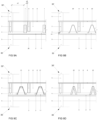
- Figs. 9A-9D show a detailed section view of part of a modular building 100, in particular showing part of the floor of the top building element '30 and the ceiling of the bottom building element 30.
- Figs. 9A-9D many shapes and materials are envisioned for the ceiling joists of the bottom building element 30, which shapes may be readily applied to any floor joist 9 as well.
- a first ceiling joist 1 of the bottom building element 30 is positioned between a first floor joist 7 and a second floor joist 9 of the top building element '30.
- a spacing s 1 between the first ceiling joist and the first floor joist may be larger than a spacing s2 between the first ceiling joist and the second floor joist.
- the spacing s2 may be larger than spacing s1 .
- one or more ducts or other installations may be positioned in the spacing s1 .
- These ducts or other installations may be of a larger size compared to a situation wherein spacings s1 and s2 would be equal or approximately equal.
- the spacings s1 and s2 may alternatively be equal.
- the spacings between adjacent floor joists may be equal for a single modular element, or may vary between different sets of adjacent floor joists.
- the spacings between adjacent ceiling joists may be equal for a single modular element, or may vary between different sets of adjacent ceiling joists.
- spacing s1 may as an option be empty between the two transverse floor beams 6, at least during assembly of the modular building - for example prior to one or more ducts or wiring being positioned in the space defined by spacing s1 .
- Fig. 9B depicts alternatively shaped ceiling joists 20.
- the ceiling joists 1 are depicted as beams with a substantially rectangular cross-section
- the ceiling joists 20 have a generally tapered cross-section, tapered upwards away from the bottom building element 30.
- Fig. 9C and 9D depict even further alternatives of ceiling joists 21, 22, which are also tapered upwards away from the bottom building element 30.
- any section shape can be envisioned.
- application of a ceiling joist with a hollow section, made of a timber based, metal, plastic or other material may increase the resistance against lateral torsional buckling.
- Any ceiling joist as for example depicted in 9C and 9D, may be made wood-based material. It will be appreciated that any ceiling joist in any embodiment of any building element disclosed herein may have any of the cross-sectional shapes detailed in Figs. 9A-9D .
- the ceiling joist 20 preferably consist of or comprise metal, such as steel. Additionally, as a further option, the ceiling joist 20 may be thin-walled, to reduce weight, for example with a thickness between 0.5 and 3 mm, in particular between 1.0 and 2.0 mm. By virtue of the trapezoidal shape of the ceiling joist 20, a chance of lateral torsional buckling is reduced, for example compared to a beam with a rectangular cross-section.
- the ceiling joists 21, 22 of respectively Fig. 9C and 9D are also designed to reduce a sensitivity to lateral torsional buckling, for example with respect to a similar joist with a rectangular cross-sectional shape.
- the ceiling joists 21 depicted in Fig. 9C are formed by thin webs, which are at their distal ends connected to a top flange, in particular a thick top flange, and at their proximal end connected to further bottom flanges, in particular thick bottom flanges, which in turn can be connected to the transverse ceiling beams 3.
- the relative wordings thin and thick imply that the thin elements have a smaller width than the thick elements.
- the thin elements for example can be a factor two, three, four or even five or more thinner than the thick elements.
- the thin elements have a thickness between 5-20 mm, in particular approximately 10 mm.
- the webs are typically made from oriented strand board or plywood, the flanges are typically made from timber or laminated veneer lumber.
- the ceiling joists 22 depicted in Fig. 9D comprise two beam elements which are slanted towards each other and are joined at their distal ends.
- the beam elements may for example comprise wood, wood-derived product, metal such as steel, or any other material.
- the beam elements may have a thickness between 10 - 40 mm, in particular between 20 - 30 mm.
- the transverse ceiling beam 3 of the bottom building element 30 is vertically structurally spaced apart from the transverse floor beam 6 of the top building element '30.
- This optional feature is also depicted for example in Fig. 12A , and can be applied to any embodiment of the modular building.
- air and/or one or more flexible and/or sound-absorbing elements may be present.
- no rigid elements extend between one or more or all of the transverse ceiling beams 3 of the bottom building element 30 and the transverse floor beams 6 of the top building element '30 in a vertical direction.
- the height of the spacing s3 may be at least in part defined by the height of the column interface element 4 positioned between the columns 5 of the top building element '30 and the columns 5 of the bottom building element 30.
- the ceiling joists form a structural element together with part of the ceiling surface 2.
- a continuous hollow cross-sectional shape is formed.
- the ceiling joist may have a hollow cross-sectional shape on its own, for example when the ceiling comprises or consists of a non-structural cladding material.
- Any ceiling joist may be formed by connecting multiple elements with a hollow cross-sectional shape and/or any ceiling joists may have multiple distinct hollow sections formed therein.
- any ceiling joist may be formed in an extrusion or pultrusion process.
- any of the ceiling joists disclosed in conjunction with Figs. 9A-9D , and any options for ceiling joists discussed herein may be readily applied to any building element, for example also any building element comprising one or more wall elements, such as but not limited to the building element 300 of Fig. 17 .
- Fig. 10 shows in an exploded view a modular building 100 comprising a top building element '30 and a bottom building element 30.
- Fig. 11 shows an exploded section of the modular building 100 of Fig. 10
- Fig. 12A shows a detailed view of the modular building 100 of Fig. 10 in assembled state, with a bracket 23 detailed in Fig. 12B .
- the building 100 of Fig. 10 is also depicted in Figs. 4A and 4B .
- brackets 23 are positioned at both ends of the ceiling joist 1, and the brackets 23 are used to connect the ceiling joists 1 to the respective transverse ceiling beams 28.
- the transverse ceiling beams 28, as depicted in Fig. 10 , but also as an option applicable to any other building element disclosed herein, may have a smaller width than the width of the columns 5 of the building element.
- the width of the transverse ceiling beams 28 may for example be half or less of the width of the columns 5, or even 40% or less, 30% or less, or even 20% or less.
- the brackets 23 are an example of how it can be achieved that the ceiling joists 1 of the bottom building element are shorter in length than at least one of the floor joists 9 of the top building element and/or a spacing between the two transversal ceiling beams 28.
- the brackets 23 may also allow the ceiling joists 1 of the bottom building element to be shorter in length than a spacing between the two transverse floor beams 6 of the top building element.
- Brackets may also be used even when one or both ends of the ceiling joists are positioned above a top surface of one or both transverse ceiling beams, for example to prevent rotation of the ceiling joists around their elongation axis.
- a bracket 23 which may be used in any building element disclosed herein to connect an end of a ceiling joist 1 to a transverse ceiling beam 28.
- the bracket 23 comprises a joist connection part 76 and a beam connection part 77.
- the bracket 23 may aid in limiting a rotation of the ceiling joist 1 around its elongation axis.
- the joist connection part 76 is in general used to form the connection between the bracket 23 and the ceiling joist 1. Although depicted with two vertical plates, conceivably the bracket 23 may also comprise a single vertical plate. To this end, for example, a reception space 78 may be formed by the joist connection 76 into which part of the ceiling joist 1 can be positioned.
- the reception space is the space enclosed by the vertical plates, or in case of a single vertical steel plate, on either side or both sides of that vertical steel plate.
- pins, bolts and/or screws may be used to hold the joist 1 in the reception space 78.
- the joist connection part can have inclined sides if the ceiling joist that should be received has a trapezoidal shape.
- the beam connection part 77 is preferably shaped corresponding to a shape of a top surface of the transversal ceiling beam 28.
- the beam connection part 77 is in general used to form the connection between the bracket 23 and the transverse ceiling beam 28.
- the beam connection part 77 may for example comprises a plate with one or more through-holes.
- a screw connection may be used to connect the beam connection part 77 to the transverse ceiling beam 28.
- Fig. 13A depicts a detailed view of another modular building 100, in which an alternative bracket 29 is used, which bracket 29 is depicted in Fig. 13B .
- the bracket 29 comprises a similar joist connection part 76 to the bracket 23 depicted in Fig. 12B .
- the beam connection part 77 of the bracket 23 of Fig. 12B will in use be typically supported on a top surface of a transverse ceiling beam 28
- the beam connection part 77 of the bracket 29 of Fig. 13B will in use typically be positioned along a side surface of a transverse ceiling beam 28.
- brackets In assembled state of the modular building 100, when using one or more brackets, for example those depicted in Figs. 12B and 13B , part of the transverse floor beams 6 of the top building element '30 can be positioned alongside the bracket. This allows for a compact design of the modular building 100.
- the brackets are formed in metal, such as steel.
- the transverse floor beams 6 of the top building element have a width at least approximately corresponding to a width of the transverse ceiling beams 3 of the bottom building element.
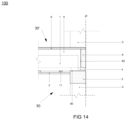
- Fig. 14 shows part of another example of a modular building 100, showing part of a top building element '30 positioned on top of a bottom building element 30.
- the brackets 23, 29 depicted in Figs. 12A-13B are merely examples of mounting brackets, and alternatively any other type of mounting bracket may be used. Although the brackets 23, 29 are in Figs. 12A-13B shown as being connected to a transverse ceiling beam 3,28, any mounting bracket may be used to connect a ceiling joist to a wall element 24, as will be elaborated on in conjunction with Figs. 17-19B .
- the transverse ceiling beams 3 of the bottom building element 30 can be wider than the transverse floor beams 6 of the top building element '30.
- the outer side faces of the transverse ceiling beam 3 and the transverse floor beam 6 are approximately aligned in a plane P.
- the transverse ceiling beams 3 of the bottom building element 30 is wider than the transverse floor beams 6 of the top building element '30, part of the top surface of the transverse ceiling beam 3 extends further into the building than the transverse floor beam 6. As such, this part of the top surface may be used for supporting one or more ceiling joist 1.
- part of the top surface 80 of the transverse ceiling beam 3 can extend into the building beyond the inner side surface 82 of the transverse floor beam 6.
- the part of the top surface 80 can be used to support an end of ceiling joist 1 onto, without the end of the ceiling joist 1 interfering with the transversal floor beam 6.
- the ceiling joists 1 are supported on a top surface of the transverse ceiling beams 3.
- the ceiling joist 1 extends over part of the width of the transverse ceiling beam 3, for example up to 75% of the width, or up to 50% of the width, or even up to 25% of the width.
- the ceiling joist 1 is shown extending to half the width of the ceiling beam 3.
- Fig. 14 shows the bottom building element 30 comprising the transverse ceiling beam 3, as for any bottom building element disclosed herein, the transverse ceiling beam 3 may be substituted by a wall element 24.
- Fig. 15 shows in an exploded view another example of a modular building 100 comprising a bottom building element 30 and a top building element '30.
- Fig. 15 indicates that many configurations of the building elements are envisioned, with for example any number of columns. In the example of Fig. 15 , both building elements comprise six columns 5.
- a building element comprises more than four columns, for example six columns 5 as depicted in Fig. 15
- multiple distinct lengths of ceiling joists 1 and/or floor joists may be used.
- a first set of ceiling joists 1 is positioned left of the central two columns 5, and a second set of ceiling joists 1 positioned right of the central two columns 5.
- a central transversal ceiling beam 3 is positioned between the first and second sets of ceiling joists 1.
- a central transversal floor beam may be comprised at least by any building element with six or more columns.
- the first and second set of ceiling joists 1 are spaced apart, such that in a spacing between the first and second set of ceiling joists 1, at least part of a central transversal floor beam of a top modular element can be accommodated.
- one or more partition walls 18, party walls 19, facade elements 16, and/or windows 17 may be comprised by any building element disclosed herein.
- a wall element 24 Any set of columns, in the example of Fig. 15 but also for any building element disclosed herein, may be substituted by a wall element 24.
- the wall elements are further elaborated on in conjunction with Figs. 17-19B .
- Fig. 16 shows yet another example of a modular building 100 within the scope of the present disclosure, in an exploded view.
- the modular building 100 comprises a top building element 30' and a bottom building element 30 which is use positioned below the top building element.
- a floor opening 15 is provided in the floor of the top building element, aligned with an opening in the ceiling of the bottom building element.
- the floor joists of the top building element positioned between the floor edge joists 7 are reduced in length.
- the ceiling joists 1 are reduced in length - i.e. they do not extend between the outermost transversal ceiling beams 3.
- the floor opening and opening in the ceiling may for example be used as a staircase.
- one or more intermediate columns 12 may be comprised by the bottom building element 30, with an intermediate transversal ceiling beam 14 on which the ceiling joists 1 are supported. Intermediate struts 13 may span between the intermediate transversal ceiling beams 14 and the transversal ceiling beam 3, or - as depicted in Fig. 16 - between the intermediate columns 12 and the outer columns 5. In general, an intermediate column 12 may be supported on the floor surface 8, or on the floor edge joist 7. No vertical coupling is typically required between the intermediate columns 12 and the top building element '30, and as such no interface element 4 is depicted in Fig. 16 above the intermediate columns 12. Any intermediate column may be formed from wood, wood-derived product, or a metal such as steel.
- FIG. 17-19B another type of modular building element 300 is elaborated. It will be appreciated that the features disclosed in conjunction with the types of modular building element disclosed in conjunction with Figs. 1-16 are readily applicable to the modular building elements of Figs. 17-19B , for example in terms of material use, shapes, dimensions, and relative dimensions of the ceiling joists and the floor joists, the use of mounting brackets, the presence of facades, partition wall, intermediate columns, and any other feature, in any combination.
- a modular building element 300 is envisioned within the context of the present disclosure.
- the modular building element 300 comprises a floor 40, a ceiling 42, and two wall elements 24 between the floor and the ceiling.
- the floor 40 comprises floor joists 7,9 spanning between the wall elements 24, and the ceiling 42 comprises ceiling joists 1 spanning between the wall elements 24.
- the ceiling may be substituted by any type of ceiling or roof.
- the floor may be substituted by any type of floor or foundation.
- the outside floor joists 7 may have the same length as the inner floor joists 9. As shown in Fig. 17 , the floor joists are positioned at least partially alongside the wall elements 24. As such, at least part of the floor joist is at the same height of at least of the wall elements.
- FIG. 18A and 19A Two examples of how two modular building elements with wall elements can be stacked on top of each other, with the ceiling joists of the bottom element and the floor joists of the top element positioned substantially parallel and at least partially side-by-side, are depicted in Figs. 18A and 19A , and Figs. 18B and 19B respectively.
- Figs. 18A and 18B depict in detail part of a modular building 1000 comprising a top building element ⁇ 300 positioned above a bottom building element 300, in a section view.
- Figs. 19A and 19B also depict in detail part of the modular building 1000, in a different section view in a plane perpendicular to the section plane used for Figs. 18A and 18B .
- At least four interface elements 400 are positioned between the top building element and the bottom building element.
- the four interface elements 400 may be positioned at or near corners of the building elements.
- the interface elements 400 may be similar to the column interface elements, and may thus have any one or more features discussed in conjunction with the column interface elements 4.
- the interface elements 400 When essentially all the weight of the top building element is transferred to the wall elements 24 of the bottom building element through the interface elements 400, transmission of sound between the top building element and bottom building element may be reduced - compared for example to a situation wherein the wall elements 24 of the building elements would be stacked directly on top of each other, or a solid element, for example a wooden element, would be positioned between the wall elements 24 over the entire width of the wall elements.
- a solid element for example a wooden element
- a vertical spacing may be present between a wall element 24 of the top building element relative to a wall element 24 of the bottom building element positioned directly below the respective wall element of the top building element.
- the interface elements 24 are the only weight-transferring elements.
- air and/or sound dampening material may be present.
- mounting brackets 23 are comprised by the bottom building element.
- the brackets may be shaped similar, and function similar, to the brackets described in conjunction with Figs. 12B and 13B .
- recesses 25 are formed in the wall elements 24 of the top building element 300.
- the recesses 25 are designed to in use accommodate ends of the ceiling joists 1 of the bottom building element 30. This allows the ceiling joists 1 of the bottom building element to be supported on a top surface of the wall elements 24 of the bottom building element.
- the recesses allow the ceiling joists 1 of the bottom building element to be longer than at least one of the floor joists 7, 9 of the top building element and/or longer than a spacing between wall elements 24 of the top building element and/or longer than a spacing between wall elements 24 of the bottom element.
- a spacing between the wall elements 24 of the top building element is essentially equal to a spacing between the wall elements 24 of the bottom building element.
- a wall thickness of the wall elements 24 of the top building element is essentially equal to a wall thickness of the wall elements 24 of the bottom building element.
- Any wall element 24 is preferably provided as a single body.
- the shape of the recesses 25 may resemble the shape of the ceiling joists 22, even when the ceiling joists 22 for example have a tapered shape.
- building elements are envisioned with on one end a set of columns 5, as explained generally in conjunction with Figs. 1-16 , and on an opposite end a wall element 24, as explained generally in conjunction with Figs. 17-19B .
- Any building element with no, one or more wall elements may be a bottom and/or top building element relative to another building with no, one or more wall elements, in any combination thereof.
- At least one ceiling joist of a bottom building element and at least one floor joist of a top building element can be positioned substantially parallel and at least partially side-by-side are for example depicted, in a non-limitative manner, in Figs. 6-7 , 9A-9D , 10 , 12A , 13A , 14 , 18A-18B , 19A and 19B .
Landscapes
- Engineering & Computer Science (AREA)
- Architecture (AREA)
- Physics & Mathematics (AREA)
- Electromagnetism (AREA)
- Civil Engineering (AREA)
- Structural Engineering (AREA)
- Floor Finish (AREA)
Applications Claiming Priority (1)
| Application Number | Priority Date | Filing Date | Title |
|---|---|---|---|
| NL2034781A NL2034781B1 (en) | 2023-05-08 | 2023-05-08 | Modular building elements |
Publications (1)
| Publication Number | Publication Date |
|---|---|
| EP4461896A1 true EP4461896A1 (fr) | 2024-11-13 |
Family
ID=86942362
Family Applications (1)
| Application Number | Title | Priority Date | Filing Date |
|---|---|---|---|
| EP24174701.3A Pending EP4461896A1 (fr) | 2023-05-08 | 2024-05-08 | Eléments de construction modulaires |
Country Status (2)
| Country | Link |
|---|---|
| EP (1) | EP4461896A1 (fr) |
| NL (1) | NL2034781B1 (fr) |
Citations (2)
| Publication number | Priority date | Publication date | Assignee | Title |
|---|---|---|---|---|
| EP2241692A2 (fr) | 2009-04-15 | 2010-10-20 | Ballast Nedam Bouw en Ontwikkeling B.V. | Module de maison, maison comprenant des modules et procédé pour construire une maison |
| EP3081713A1 (fr) * | 2014-10-15 | 2016-10-19 | Keystone Lintels Limited | Agencement amélioré de solive de plancher/plafond |
-
2023
- 2023-05-08 NL NL2034781A patent/NL2034781B1/en active
-
2024
- 2024-05-08 EP EP24174701.3A patent/EP4461896A1/fr active Pending
Patent Citations (2)
| Publication number | Priority date | Publication date | Assignee | Title |
|---|---|---|---|---|
| EP2241692A2 (fr) | 2009-04-15 | 2010-10-20 | Ballast Nedam Bouw en Ontwikkeling B.V. | Module de maison, maison comprenant des modules et procédé pour construire une maison |
| EP3081713A1 (fr) * | 2014-10-15 | 2016-10-19 | Keystone Lintels Limited | Agencement amélioré de solive de plancher/plafond |
Also Published As
| Publication number | Publication date |
|---|---|
| NL2034781B1 (en) | 2024-11-25 |
Similar Documents
| Publication | Publication Date | Title |
|---|---|---|
| CA2692723C (fr) | Panneau de toit isole structurel dote d'une ame en mousse rigide | |
| US6205729B1 (en) | Asymmetric structural insulated panel | |
| US20080083180A1 (en) | Structural insulated panels with a rigid foam core and without thermal bridging | |
| CA2111149A1 (fr) | Systeme de construction a ossature de bois utilisant des elements prefabriques | |
| EP0916778B1 (fr) | Linteau | |
| US11255084B2 (en) | Thermal break wood columns, buttresses and headers with rigid insulation | |
| EP3892786A1 (fr) | Module linéaire pour bâtiments pour la réalisation de cadres structurels de bâtiments préfabriqués avec isolation thermique, kit pour bâtiments et bâtiment préfabriqué correspondant | |
| WO2017058095A1 (fr) | Section composite de fibres et assemblage | |
| WO2021021633A1 (fr) | Système de panneau structural pour mur | |
| WO2023102178A1 (fr) | Élément structural modifié isolé | |
| WO2001059228A1 (fr) | Element mural | |
| EP4461896A1 (fr) | Eléments de construction modulaires | |
| WO2020117115A1 (fr) | Élément de construction, unités de logement modulaires, bâtiments et procédé | |
| US20040226255A1 (en) | Composite beam | |
| US20050102962A1 (en) | Timber block | |
| EP1811097B1 (fr) | Élément de construction | |
| JP2013511636A (ja) | 木製壁を構成する要素一式および該要素を使用する方法 | |
| WO2004109032A1 (fr) | Poutres en bois contreventees | |
| EP4074912A1 (fr) | Poutrelle pour bâtiments et ponts | |
| EP1953300B1 (fr) | Agencement pour assemblage d'éléments de construction à base de bois | |
| CN223689167U (zh) | 一种薄壁h型钢竹或钢木组合楼板连接节点 | |
| US20250034870A1 (en) | Structural building material | |
| CN215563808U (zh) | 一种立式拼接式节能整体轻质预制混凝土墙板 | |
| WO2025158101A1 (fr) | Élément de paroi préfabriqué | |
| CN118110299A (zh) | 一种竹木钢塑组合楼面板及生产方法 |
Legal Events
| Date | Code | Title | Description |
|---|---|---|---|
| PUAI | Public reference made under article 153(3) epc to a published international application that has entered the european phase |
Free format text: ORIGINAL CODE: 0009012 |
|
| STAA | Information on the status of an ep patent application or granted ep patent |
Free format text: STATUS: THE APPLICATION HAS BEEN PUBLISHED |
|
| AK | Designated contracting states |
Kind code of ref document: A1 Designated state(s): AL AT BE BG CH CY CZ DE DK EE ES FI FR GB GR HR HU IE IS IT LI LT LU LV MC ME MK MT NL NO PL PT RO RS SE SI SK SM TR |
|
| P01 | Opt-out of the competence of the unified patent court (upc) registered |
Free format text: CASE NUMBER: APP_61286/2024 Effective date: 20241115 |
|
| STAA | Information on the status of an ep patent application or granted ep patent |
Free format text: STATUS: REQUEST FOR EXAMINATION WAS MADE |
|
| 17P | Request for examination filed |
Effective date: 20250512 |