EP4461993A1 - Trimmbarer sekundärlastpfaddetektor für horizontalen stabilisatoraktuator - Google Patents
Trimmbarer sekundärlastpfaddetektor für horizontalen stabilisatoraktuator Download PDFInfo
- Publication number
- EP4461993A1 EP4461993A1 EP23305758.7A EP23305758A EP4461993A1 EP 4461993 A1 EP4461993 A1 EP 4461993A1 EP 23305758 A EP23305758 A EP 23305758A EP 4461993 A1 EP4461993 A1 EP 4461993A1
- Authority
- EP
- European Patent Office
- Prior art keywords
- lock
- assembly
- opening
- transfer plate
- plate
- Prior art date
- Legal status (The legal status is an assumption and is not a legal conclusion. Google has not performed a legal analysis and makes no representation as to the accuracy of the status listed.)
- Pending
Links
Images

Classifications
-
- F—MECHANICAL ENGINEERING; LIGHTING; HEATING; WEAPONS; BLASTING
- F16—ENGINEERING ELEMENTS AND UNITS; GENERAL MEASURES FOR PRODUCING AND MAINTAINING EFFECTIVE FUNCTIONING OF MACHINES OR INSTALLATIONS; THERMAL INSULATION IN GENERAL
- F16H—GEARING
- F16H25/00—Gearings comprising primarily only cams, cam-followers and screw-and-nut mechanisms
- F16H25/18—Gearings comprising primarily only cams, cam-followers and screw-and-nut mechanisms for conveying or interconverting oscillating or reciprocating motions
- F16H25/20—Screw mechanisms
- F16H25/205—Screw mechanisms comprising alternate power paths, e.g. for fail safe back-up
-
- B—PERFORMING OPERATIONS; TRANSPORTING
- B64—AIRCRAFT; AVIATION; COSMONAUTICS
- B64C—AEROPLANES; HELICOPTERS
- B64C13/00—Control systems or transmitting systems for actuating flying-control surfaces, lift-increasing flaps, air brakes, or spoilers
- B64C13/24—Transmitting means
- B64C13/26—Transmitting means without power amplification or where power amplification is irrelevant
- B64C13/28—Transmitting means without power amplification or where power amplification is irrelevant mechanical
- B64C13/341—Transmitting means without power amplification or where power amplification is irrelevant mechanical having duplication or stand-by provisions
-
- F—MECHANICAL ENGINEERING; LIGHTING; HEATING; WEAPONS; BLASTING
- F16—ENGINEERING ELEMENTS AND UNITS; GENERAL MEASURES FOR PRODUCING AND MAINTAINING EFFECTIVE FUNCTIONING OF MACHINES OR INSTALLATIONS; THERMAL INSULATION IN GENERAL
- F16H—GEARING
- F16H25/00—Gearings comprising primarily only cams, cam-followers and screw-and-nut mechanisms
- F16H25/18—Gearings comprising primarily only cams, cam-followers and screw-and-nut mechanisms for conveying or interconverting oscillating or reciprocating motions
- F16H25/20—Screw mechanisms
- F16H25/24—Elements essential to such mechanisms, e.g. screws, nuts
- F16H25/2472—Safety nuts
-
- B—PERFORMING OPERATIONS; TRANSPORTING
- B64—AIRCRAFT; AVIATION; COSMONAUTICS
- B64C—AEROPLANES; HELICOPTERS
- B64C5/00—Stabilising surfaces
- B64C5/02—Tailplanes
-
- B—PERFORMING OPERATIONS; TRANSPORTING
- B64—AIRCRAFT; AVIATION; COSMONAUTICS
- B64C—AEROPLANES; HELICOPTERS
- B64C5/00—Stabilising surfaces
- B64C5/10—Stabilising surfaces adjustable
- B64C5/16—Stabilising surfaces adjustable about spanwise axes
-
- B—PERFORMING OPERATIONS; TRANSPORTING
- B64—AIRCRAFT; AVIATION; COSMONAUTICS
- B64D—EQUIPMENT FOR FITTING IN OR TO AIRCRAFT; FLIGHT SUITS; PARACHUTES; ARRANGEMENT OR MOUNTING OF POWER PLANTS OR PROPULSION TRANSMISSIONS IN AIRCRAFT
- B64D45/00—Aircraft indicators or protectors not otherwise provided for
- B64D2045/0085—Devices for aircraft health monitoring, e.g. monitoring flutter or vibration
Definitions
- the disclosure relates to an assembly for a flight actuator such as a trimmable horizontal stabiliser actuator (THSA).
- THSA trimmable horizontal stabiliser actuator
- THSA trimmable horizontal stabiliser actuator
- a flight actuator it is well known for a flight actuator to include two mechanical load paths, one primary and the other secondary, with the latter intended to take up the load when the primary path has failed.
- a typical actuator such as a THSA
- the loads are transmitted from the screw through a primary nut.
- the assembly includes a failsafe plate, which is connected to the primary nut with a small amount of play.
- the failsafe plate During normal operation, when the primary load path is working correctly, the secondary load path formed by this failsafe plate carries no load since there is no contact due to the small amount of play.
- the failsafe plate performs its failsafe function and ensures continuity of the transmission of loads by the actuator via the secondary load path.
- failsafe features are generally reliable, they can fail. It is important, particularly in safety critical applications such as aircraft, to have some reliable means for detecting when the load is being carried by the secondary load path. In the aircraft industry, regulations require such a function to be in place. Whilst it may be that a manual check is required, some assemblies do have devices to check for engagement of the secondary load path. Furthermore, the health/integrity of the means for detecting engagement of the secondary load path must itself be checkable. Again, in the aircraft industry, this is a regulatory requirement.
- loading of the secondary load path is detected by a so-called checkable shear pin. This is provided on a lower attachment secondary load path of the THSA. In the event of primary load failure, the checkable shear pin will provide an indication to the flight control computers of the secondary load path engagement.
- a secondary load path assembly comprising: a secondary load path comprising: a plate; a secondary nut; and a transfer plate secured to the plate and configured to connect the plate and the secondary nut in load transfer engagement, the transfer plate having an opening therethrough, an axis defined through the opening, and the secondary nut protruding axially through the opening; wherein, in a state in which load is not transmitted via the secondary load path, a clearance is provided between the secondary nut and the opening; the assembly further comprising: a locking unit configured to lock the secondary nut to the transfer plate when load is to be transmitted through the secondary path, the locking unit comprising a lock arranged to axially move to a lock position in which it is located in the clearance between the secondary nut and the opening to lock the secondary nut to the transfer plate.
- the secondary load transfer path is part of a load transfer assembly such as a THSA with a primary load transfer path.
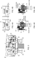
- a typical known flight control actuator 10 of the trimmable horizontal stabiliser actuator (THSA) type includes a primary load path with a hollow screw 20 connected at its upper end to the aircraft via a Cardan joint system 30 joining with first aircraft structural elements (not shown).
- the primary load path further includes a primary nut 25 mounted on the screw 20, and the primary nut 25 is connected to the stabiliser (not shown) of the aircraft.
- the primary nut 25 is loaded by an external load at the bearing 40 level and a gimbal 50. In other words, the loads transfer from the stabiliser and bearing 40 to the gimbal 50 and the screw 20.
- the secondary load path parts (described further below) are not engaged due to a clearance between the transfer plate 65 and the secondary nut 70.
- the load passes, instead, to the failsafe plate 60 to a transfer plate 65 to a secondary nut 70 around the screw 25 - i.e. along the secondary load path. There is relative movement between the transfer plate 65 and the secondary nut 70 to close the clearance and engage the secondary load path parts.
- the failsafe plate 60 is securely attached to the aircraft such that if, for example, only one bearing fails (i.e. on one side of the assembly), the entire secondary load path with translate.
- the assembly according to this disclosure therefore functions to securely lock the failsafe plate 60, via the transfer plate 65, to the secondary nut 70 when the secondary load path is engaged, to avoid backlash.
- the assembly comprises a locking unit 80 that is mounted to the transfer plate 65 e.g. by means of a nut and bolt 81 or other fastener.
- a maintenance cap 90 is affixed to cover the locking components parts (described further below) in the locking unit 80.
- the maintenance cap 90 may be fastened by screws or nuts and bolts or other fasteners 91.
- two such locking units are provided, one on each side of the load path assembly, between the opposing failsafe plates 60, as seen in Fig. 3 .
- a switch 85 is located in and extends from the locking unit 80.
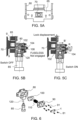
- the locking component parts comprise a slidable lock 100, slidably located within the body of the locking unit 80 and a lock spring 110 extending into and arranged to bias the lock for movement in the body of the lock unit.
- a ball 120 is located between the end 851 of the switch 85 that extends into the locking unit 80 and the slidable lock 100 as will be described further below.
- the slidable lock has a locking end 102 and an opposite end 103 in engagement with the spring 110.
- the opposite end has a greater diameter than the locking end, the locking end having a smaller diameter than the interior of the body of the locking unit, the opposite end having a diameter approximately equal to the body interior, while still allowing slidable movement between the lock and the body interior.
- a curved recess 108 is formed in the wide diameter part of the lock between the locking end and the opposite end, shaped and sized to receive the ball 120 when the lock is in the unlocked position ( Fig. 4C and 5B ).
- Figs. 4A and 4C show the assembly in normal operating condition when load is transferred via the primary load path and the secondary load path is not engaged.
- a clearance g e.g. around 4 mm, but this is only one example and the clearance will depend on the design and application
- the clearance will be all around the secondary nut between the nut and the opening 650 so that there is not force transfer engagement between the transfer plate and the secondary nut.
- the sectional view through the lock unit, in this unlocked state is shown in Fig. 4C .
- the lock 100 here is seated behind the secondary nut, and forced by the secondary nut inside the locking unit 80, and compresses the spring 110.
- the lock unit 80 of this disclosure therefore operates to provide this locking engagement in the state of the secondary load path being engaged.
- Fig. 4D which shows a cross-section through the lock unit in the locked position
- the transfer plate 65 moves down (arrow A) relative to the secondary nut 70, so that they engage along the top edge 651 of the opening 650
- the slidable lock 100 moves down relative to the secondary nut.
- the lock 100 is shaped to have a locking end 102 that has a size corresponding to the larger gap G created when the top gap is closed and edge 651 is in contact with the transfer plate 65 and as this locking end 102 moves down (A) into alignment with the larger gap G it is able to move into that gap G under the force of the spring 110, as the spring expands. This then blocks any relative movement between the secondary nut and the transfer plate.
- the slidable lock 100 moves (in direction B) into the gap G to lock the secondary nut, it also slides over the ball 120 and is configured to push the ball down (direction A) against the end 851 of the switch 85. This activates the switch and the switch then provides an indication (e.g. to the flight control computer or to personnel) that the secondary load path is engaged (and locked).
- the assembly therefore provides reliable locking and detection of the engagement of the secondary load path.
- a screw or the like is engaged with the end 104 (opposite the locking end 102) of the lock 100 and is used to rotate (direction R (either clockwise or anti-clockwise) the lock to cause the lock to move in a direction B' away from the secondary nut in the lock unit.
- the lock therefore moves against the force of the spring 110, further compressing the spring and slides over the ball 120 such that the recess 106 moves away from the ball 120 and the body of the slider adjacent the recess (between the recess and the locking end 102) pushes against the ball 120 against the end 851 of the switch 85 in direction A to activate the switch.
- the switch then indicates that the lock is able to move and is not jammed, which confirms reliable functioning of the lock.
- the assembly of this disclosure is therefore able to ensure locking of the secondary load path parts when needed, as well as providing a reliable indication that the secondary load path is engaged and is also capable of being checked in a simple and reliable manner. No 'fuses' - i.e. parts that are destroyed to provide the engagement indication - are used and so the assembly is re-usable and does not require the assembly to be dismantled for re-setting/re-use.
Landscapes
- Engineering & Computer Science (AREA)
- General Engineering & Computer Science (AREA)
- Mechanical Engineering (AREA)
- Automation & Control Theory (AREA)
- Aviation & Aerospace Engineering (AREA)
- Transmission Devices (AREA)
- Connection Of Plates (AREA)
Priority Applications (3)
| Application Number | Priority Date | Filing Date | Title |
|---|---|---|---|
| EP23305758.7A EP4461993A1 (de) | 2023-05-12 | 2023-05-12 | Trimmbarer sekundärlastpfaddetektor für horizontalen stabilisatoraktuator |
| CA3233171A CA3233171A1 (en) | 2023-05-12 | 2024-03-25 | Trimmable horizontal stabiliser actuator secondary load path detector |
| US18/662,263 US12510140B2 (en) | 2023-05-12 | 2024-05-13 | Trimmable horizontal stabiliser actuator secondary load path detector |
Applications Claiming Priority (1)
| Application Number | Priority Date | Filing Date | Title |
|---|---|---|---|
| EP23305758.7A EP4461993A1 (de) | 2023-05-12 | 2023-05-12 | Trimmbarer sekundärlastpfaddetektor für horizontalen stabilisatoraktuator |
Publications (1)
| Publication Number | Publication Date |
|---|---|
| EP4461993A1 true EP4461993A1 (de) | 2024-11-13 |
Family
ID=86604819
Family Applications (1)
| Application Number | Title | Priority Date | Filing Date |
|---|---|---|---|
| EP23305758.7A Pending EP4461993A1 (de) | 2023-05-12 | 2023-05-12 | Trimmbarer sekundärlastpfaddetektor für horizontalen stabilisatoraktuator |
Country Status (3)
| Country | Link |
|---|---|
| US (1) | US12510140B2 (de) |
| EP (1) | EP4461993A1 (de) |
| CA (1) | CA3233171A1 (de) |
Families Citing this family (1)
| Publication number | Priority date | Publication date | Assignee | Title |
|---|---|---|---|---|
| CN121302772A (zh) * | 2025-09-30 | 2026-01-09 | 北京控制工程研究所 | 复杂工况任务下作动器载荷和寿命分析的试验方法 |
Citations (3)
| Publication number | Priority date | Publication date | Assignee | Title |
|---|---|---|---|---|
| US20160281826A1 (en) * | 2015-03-27 | 2016-09-29 | Goodrich Actuation Systems Sas | Lower attachment for trimmable horizontal stabiliser actuator |
| US20180194454A1 (en) * | 2017-01-10 | 2018-07-12 | Parker-Hannifin Corporation | Moving end electronic detection of secondary load path engagement of aircraft flight control actuator |
| EP3789294A1 (de) * | 2019-09-04 | 2021-03-10 | Goodrich Actuation Systems SAS | Aktuator |
Family Cites Families (3)
| Publication number | Priority date | Publication date | Assignee | Title |
|---|---|---|---|---|
| US8985510B2 (en) | 2011-11-15 | 2015-03-24 | Parker-Hannifin Corporation | Tie rod lock |
| EP3127805B1 (de) | 2015-08-07 | 2021-03-17 | Goodrich Actuation Systems SAS | Untere befestigung für einen trimmbaren horizontalen stabilisatoraktuator |
| US10974846B2 (en) | 2016-12-09 | 2021-04-13 | Parker-Hannifin Corporation | Fixed end electronic detection of secondary load path engagement of aircraft flight control actuator |
-
2023
- 2023-05-12 EP EP23305758.7A patent/EP4461993A1/de active Pending
-
2024
- 2024-03-25 CA CA3233171A patent/CA3233171A1/en active Pending
- 2024-05-13 US US18/662,263 patent/US12510140B2/en active Active
Patent Citations (3)
| Publication number | Priority date | Publication date | Assignee | Title |
|---|---|---|---|---|
| US20160281826A1 (en) * | 2015-03-27 | 2016-09-29 | Goodrich Actuation Systems Sas | Lower attachment for trimmable horizontal stabiliser actuator |
| US20180194454A1 (en) * | 2017-01-10 | 2018-07-12 | Parker-Hannifin Corporation | Moving end electronic detection of secondary load path engagement of aircraft flight control actuator |
| EP3789294A1 (de) * | 2019-09-04 | 2021-03-10 | Goodrich Actuation Systems SAS | Aktuator |
Also Published As
| Publication number | Publication date |
|---|---|
| US20240376967A1 (en) | 2024-11-14 |
| US12510140B2 (en) | 2025-12-30 |
| CA3233171A1 (en) | 2025-06-20 |
Similar Documents
| Publication | Publication Date | Title |
|---|---|---|
| EP3282146B1 (de) | Sekundärlastpfaddetektion | |
| US8985510B2 (en) | Tie rod lock | |
| US20130001357A1 (en) | Horizontal stabilizer trim actuator failure detection system and method using position sensors | |
| US6928895B2 (en) | Ballscrew locking nut | |
| US8191824B2 (en) | Integrated load sensing system | |
| US6851648B2 (en) | Ball screw actuator for aircraft control surfaces | |
| US11209074B2 (en) | Lower attachment for trimmable horizontal stabiliser actuator | |
| US8714479B1 (en) | Centering, release and reset mechanism | |
| US10974811B2 (en) | Upper attachment for trimmable horizontal stabiliser actuator | |
| US12510140B2 (en) | Trimmable horizontal stabiliser actuator secondary load path detector | |
| US20170036754A1 (en) | Lower Attachment for Trimmable Horizontal Stabiliser Actuator | |
| US12540659B2 (en) | Screw actuators | |
| US4909364A (en) | Latching failure detection mechanism for rotary drive systems | |
| US11198501B2 (en) | Actuator upper attachment | |
| BR102024006308A2 (pt) | Conjunto de via de carga secundária, conjunto de eixos transmissores de força, e, atuador de estabilizador horizontal regulável | |
| US12420911B2 (en) | Lower attachment for trimmable horizontal stabiliser actuator | |
| US4984473A (en) | Torque monitor |
Legal Events
| Date | Code | Title | Description |
|---|---|---|---|
| PUAI | Public reference made under article 153(3) epc to a published international application that has entered the european phase |
Free format text: ORIGINAL CODE: 0009012 |
|
| STAA | Information on the status of an ep patent application or granted ep patent |
Free format text: STATUS: THE APPLICATION HAS BEEN PUBLISHED |
|
| AK | Designated contracting states |
Kind code of ref document: A1 Designated state(s): AL AT BE BG CH CY CZ DE DK EE ES FI FR GB GR HR HU IE IS IT LI LT LU LV MC ME MK MT NL NO PL PT RO RS SE SI SK SM TR |
|
| STAA | Information on the status of an ep patent application or granted ep patent |
Free format text: STATUS: REQUEST FOR EXAMINATION WAS MADE |
|
| 17P | Request for examination filed |
Effective date: 20250513 |
|
| GRAP | Despatch of communication of intention to grant a patent |
Free format text: ORIGINAL CODE: EPIDOSNIGR1 |
|
| STAA | Information on the status of an ep patent application or granted ep patent |
Free format text: STATUS: GRANT OF PATENT IS INTENDED |
|
| RIC1 | Information provided on ipc code assigned before grant |
Ipc: F16H 25/20 20060101AFI20260205BHEP Ipc: B64C 13/28 20060101ALI20260205BHEP Ipc: F16H 25/24 20060101ALI20260205BHEP Ipc: B64C 5/16 20060101ALN20260205BHEP Ipc: B64C 5/02 20060101ALN20260205BHEP |
|
| RIC1 | Information provided on ipc code assigned before grant |
Ipc: F16H 25/20 20060101AFI20260219BHEP Ipc: B64C 13/28 20060101ALI20260219BHEP Ipc: F16H 25/24 20060101ALI20260219BHEP Ipc: B64C 5/16 20060101ALN20260219BHEP Ipc: B64C 5/02 20060101ALN20260219BHEP |
|
| INTG | Intention to grant announced |
Effective date: 20260303 |