EP4462014A1 - Dispositif d'éclairage pour un phare de véhicule automobile et phare de véhicule automobile - Google Patents
Dispositif d'éclairage pour un phare de véhicule automobile et phare de véhicule automobile Download PDFInfo
- Publication number
- EP4462014A1 EP4462014A1 EP23173075.5A EP23173075A EP4462014A1 EP 4462014 A1 EP4462014 A1 EP 4462014A1 EP 23173075 A EP23173075 A EP 23173075A EP 4462014 A1 EP4462014 A1 EP 4462014A1
- Authority
- EP
- European Patent Office
- Prior art keywords
- light
- signlight
- coupling element
- light source
- distribution
- Prior art date
- Legal status (The legal status is an assumption and is not a legal conclusion. Google has not performed a legal analysis and makes no representation as to the accuracy of the status listed.)
- Pending
Links
Images


Classifications
-
- F—MECHANICAL ENGINEERING; LIGHTING; HEATING; WEAPONS; BLASTING
- F21—LIGHTING
- F21S—NON-PORTABLE LIGHTING DEVICES; SYSTEMS THEREOF; VEHICLE LIGHTING DEVICES SPECIALLY ADAPTED FOR VEHICLE EXTERIORS
- F21S41/00—Illuminating devices specially adapted for vehicle exteriors, e.g. headlamps
- F21S41/10—Illuminating devices specially adapted for vehicle exteriors, e.g. headlamps characterised by the light source
- F21S41/14—Illuminating devices specially adapted for vehicle exteriors, e.g. headlamps characterised by the light source characterised by the type of light source
- F21S41/141—Light emitting diodes [LED]
-
- F—MECHANICAL ENGINEERING; LIGHTING; HEATING; WEAPONS; BLASTING
- F21—LIGHTING
- F21S—NON-PORTABLE LIGHTING DEVICES; SYSTEMS THEREOF; VEHICLE LIGHTING DEVICES SPECIALLY ADAPTED FOR VEHICLE EXTERIORS
- F21S41/00—Illuminating devices specially adapted for vehicle exteriors, e.g. headlamps
- F21S41/20—Illuminating devices specially adapted for vehicle exteriors, e.g. headlamps characterised by refractors, transparent cover plates, light guides or filters
- F21S41/25—Projection lenses
- F21S41/27—Thick lenses
-
- F—MECHANICAL ENGINEERING; LIGHTING; HEATING; WEAPONS; BLASTING
- F21—LIGHTING
- F21S—NON-PORTABLE LIGHTING DEVICES; SYSTEMS THEREOF; VEHICLE LIGHTING DEVICES SPECIALLY ADAPTED FOR VEHICLE EXTERIORS
- F21S41/00—Illuminating devices specially adapted for vehicle exteriors, e.g. headlamps
- F21S41/20—Illuminating devices specially adapted for vehicle exteriors, e.g. headlamps characterised by refractors, transparent cover plates, light guides or filters
- F21S41/285—Refractors, transparent cover plates, light guides or filters not provided in groups F21S41/24 - F21S41/2805
-
- F—MECHANICAL ENGINEERING; LIGHTING; HEATING; WEAPONS; BLASTING
- F21—LIGHTING
- F21S—NON-PORTABLE LIGHTING DEVICES; SYSTEMS THEREOF; VEHICLE LIGHTING DEVICES SPECIALLY ADAPTED FOR VEHICLE EXTERIORS
- F21S41/00—Illuminating devices specially adapted for vehicle exteriors, e.g. headlamps
- F21S41/10—Illuminating devices specially adapted for vehicle exteriors, e.g. headlamps characterised by the light source
- F21S41/14—Illuminating devices specially adapted for vehicle exteriors, e.g. headlamps characterised by the light source characterised by the type of light source
- F21S41/141—Light emitting diodes [LED]
- F21S41/143—Light emitting diodes [LED] the main emission direction of the LED being parallel to the optical axis of the illuminating device
-
- F—MECHANICAL ENGINEERING; LIGHTING; HEATING; WEAPONS; BLASTING
- F21—LIGHTING
- F21S—NON-PORTABLE LIGHTING DEVICES; SYSTEMS THEREOF; VEHICLE LIGHTING DEVICES SPECIALLY ADAPTED FOR VEHICLE EXTERIORS
- F21S41/00—Illuminating devices specially adapted for vehicle exteriors, e.g. headlamps
- F21S41/10—Illuminating devices specially adapted for vehicle exteriors, e.g. headlamps characterised by the light source
- F21S41/14—Illuminating devices specially adapted for vehicle exteriors, e.g. headlamps characterised by the light source characterised by the type of light source
- F21S41/18—Combination of light sources of different types or shapes
-
- F—MECHANICAL ENGINEERING; LIGHTING; HEATING; WEAPONS; BLASTING
- F21—LIGHTING
- F21S—NON-PORTABLE LIGHTING DEVICES; SYSTEMS THEREOF; VEHICLE LIGHTING DEVICES SPECIALLY ADAPTED FOR VEHICLE EXTERIORS
- F21S41/00—Illuminating devices specially adapted for vehicle exteriors, e.g. headlamps
- F21S41/20—Illuminating devices specially adapted for vehicle exteriors, e.g. headlamps characterised by refractors, transparent cover plates, light guides or filters
- F21S41/25—Projection lenses
- F21S41/255—Lenses with a front view of circular or truncated circular outline
-
- F—MECHANICAL ENGINEERING; LIGHTING; HEATING; WEAPONS; BLASTING
- F21—LIGHTING
- F21S—NON-PORTABLE LIGHTING DEVICES; SYSTEMS THEREOF; VEHICLE LIGHTING DEVICES SPECIALLY ADAPTED FOR VEHICLE EXTERIORS
- F21S41/00—Illuminating devices specially adapted for vehicle exteriors, e.g. headlamps
- F21S41/30—Illuminating devices specially adapted for vehicle exteriors, e.g. headlamps characterised by reflectors
- F21S41/32—Optical layout thereof
-
- F—MECHANICAL ENGINEERING; LIGHTING; HEATING; WEAPONS; BLASTING
- F21—LIGHTING
- F21S—NON-PORTABLE LIGHTING DEVICES; SYSTEMS THEREOF; VEHICLE LIGHTING DEVICES SPECIALLY ADAPTED FOR VEHICLE EXTERIORS
- F21S41/00—Illuminating devices specially adapted for vehicle exteriors, e.g. headlamps
- F21S41/40—Illuminating devices specially adapted for vehicle exteriors, e.g. headlamps characterised by screens, non-reflecting members, light-shielding members or fixed shades
-
- F—MECHANICAL ENGINEERING; LIGHTING; HEATING; WEAPONS; BLASTING
- F21—LIGHTING
- F21W—INDEXING SCHEME ASSOCIATED WITH SUBCLASSES F21K, F21L, F21S and F21V, RELATING TO USES OR APPLICATIONS OF LIGHTING DEVICES OR SYSTEMS
- F21W2102/00—Exterior vehicle lighting devices for illuminating purposes
- F21W2102/10—Arrangement or contour of the emitted light
- F21W2102/13—Arrangement or contour of the emitted light for high-beam region or low-beam region
- F21W2102/135—Arrangement or contour of the emitted light for high-beam region or low-beam region the light having cut-off lines, i.e. clear borderlines between emitted regions and dark regions
- F21W2102/14—Arrangement or contour of the emitted light for high-beam region or low-beam region the light having cut-off lines, i.e. clear borderlines between emitted regions and dark regions having vertical cut-off lines; specially adapted for adaptive high beams, i.e. wherein the beam is broader but avoids glaring other road users
- F21W2102/145—Arrangement or contour of the emitted light for high-beam region or low-beam region the light having cut-off lines, i.e. clear borderlines between emitted regions and dark regions having vertical cut-off lines; specially adapted for adaptive high beams, i.e. wherein the beam is broader but avoids glaring other road users wherein the light is emitted between two parallel vertical cutoff lines, e.g. selectively emitted rectangular-shaped high beam
-
- F—MECHANICAL ENGINEERING; LIGHTING; HEATING; WEAPONS; BLASTING
- F21—LIGHTING
- F21W—INDEXING SCHEME ASSOCIATED WITH SUBCLASSES F21K, F21L, F21S and F21V, RELATING TO USES OR APPLICATIONS OF LIGHTING DEVICES OR SYSTEMS
- F21W2102/00—Exterior vehicle lighting devices for illuminating purposes
- F21W2102/10—Arrangement or contour of the emitted light
- F21W2102/17—Arrangement or contour of the emitted light for regions other than high beam or low beam
- F21W2102/18—Arrangement or contour of the emitted light for regions other than high beam or low beam for overhead signs
-
- F—MECHANICAL ENGINEERING; LIGHTING; HEATING; WEAPONS; BLASTING
- F21—LIGHTING
- F21W—INDEXING SCHEME ASSOCIATED WITH SUBCLASSES F21K, F21L, F21S and F21V, RELATING TO USES OR APPLICATIONS OF LIGHTING DEVICES OR SYSTEMS
- F21W2107/00—Use or application of lighting devices on or in particular types of vehicles
- F21W2107/10—Use or application of lighting devices on or in particular types of vehicles for land vehicles
-
- F—MECHANICAL ENGINEERING; LIGHTING; HEATING; WEAPONS; BLASTING
- F21—LIGHTING
- F21Y—INDEXING SCHEME ASSOCIATED WITH SUBCLASSES F21K, F21L, F21S and F21V, RELATING TO THE FORM OR THE KIND OF THE LIGHT SOURCES OR OF THE COLOUR OF THE LIGHT EMITTED
- F21Y2115/00—Light-generating elements of semiconductor light sources
- F21Y2115/10—Light-emitting diodes [LED]
Definitions
- the invention relates to a motor vehicle headlight with at least one such lighting device.
- the lighting devices described above are known from the prior art, in which, by modifying the light-permeable body, the light coupling element or the projection device, a sign light distribution can be generated in addition to a front or low beam distribution with the at least one light source.
- the lighting device has at least one further light source, the so-called signlight light source, and a further signlight light coupling element assigned to the signlight light source, wherein the signlight light coupling element forms the light emitted by the signlight light source into a third light beam and directs the third light beam onto the boundary surface, so that light rays, in particular essentially all light rays of the third light beam, enter the translucent body, and wherein at least a portion, preferably all light rays that have entered the translucent body again are projected by the projection optics device as a signlight light beam into a region of the light distribution lying above the light-dark boundary, and are imaged, for example as a signlight light distribution.
- the signlight light source can be switched off (or dimmed) in partial high beam operation, so that no undesirable scattered radiation can emanate from the signlight in this operating state.
- Partial high beam operation is an operating state in which one or more areas, so-called segments, are excluded from a high beam distribution, for example to prevent dazzling of oncoming traffic or traffic ahead.
- the signlight light source In an operating state in which the light distribution, in particular an apron light distribution or a low beam distribution, is generated with the at least one light source, the signlight light source can be switched on so that a signlight light distribution is generated in addition to the light distribution, independently of this.
- the signlight light distribution is generated together with the apron or low beam (ie, the at least one light source responsible for generating the apron or low beam distribution is also responsible for generating the signlight light distribution) and cannot be switched off independently of this.
- the invention accordingly offers advantages in terms of the glare value, particularly when the lighting device is operated in ADB mode ("Advanced Driving Beam"), in which individual areas or segments of a (partial) high beam distribution can be switched off. Because the sign light is switched off in this operating state, in contrast to the prior art, this cannot cause glare in the masked area or in the masked/switched off segments.
- the reduction of unwanted "residual light" made possible by the invention, particularly in masked areas, can increase safety for all road users.
- the sign light can be switched on to make it easier for the driver to read overhead signposts, for example.
- the signlight light coupling element contacts the light coupling element in a common contact area or in a common contact surface. This has the advantage, particularly when the two elements are made of the same material, that the passing light rays are not deflected in their direction of propagation and can therefore also be better controlled in terms of design.
- the contact region or the contact surface is advantageously positioned in such a way, for example in relation to or at a distance from the at least one light source, that at least a portion of the light rays coming from the light source, which enter the Signlight light coupling element via the contact region or the contact surface, are totally reflected at a light exit surface of the Signlight light coupling element.
- This light therefore does not contribute to the light distribution and is deflected into an area where it remains unused and is, for example, absorbed.
- the contact area or the contact surface is positioned in such a way, for example in relation to or at a distance from the at least one light source, that at least a part of those light rays coming from the light source which are incident on a Light coupling element boundary surface of the light coupling element, are totally reflected at the light coupling element boundary surface into the light coupling element in the direction of the light-permeable body.
- This light can therefore contribute to the light distribution, e.g. to the apron or dipped beam distribution.
- the signlight light source is positioned as close as possible to a light coupling surface of the signlight light coupling element in order to be able to capture as much light as possible and to reduce as much as possible rays emanating from the signlight light source that could enter the light coupling element as interference radiation.
- a light coupling surface of the Signlight light coupling element is concave and/or a light exit surface of the Signlight light coupling element is convex.
- the signlight light coupling element has a focal point and the signlight light source is arranged substantially at the focal point.
- the light coupling surface is preferably designed to be as concave as possible in order to increase the coupling efficiency by arranging the light source in the concave cavity resulting from this design, preferably as deep as possible, and thus being enclosed by the light coupling surface at least in that angular range in which the light source emits light.
- the scattered light Due to the preferably convex light exit surface, the scattered light is largely totally reflected and deflected backwards.
- the design of the light coupling surface which is particularly strongly curved, enables a light exit surface that is as curved as possible, so that light rays coming from the light coupling element, which are coupled into the Signlight light coupling element, are deflected by total reflection at the light exit surface, so that they cannot exit the Signlight light coupling element in the direction of light propagation.
- This scattered light is preferably redirected backwards, opposite to the actual direction of light propagation.
- signlight light coupling element and the light coupling element are formed in one piece, in particular from the same material, for example by the signlight light coupling element and the light coupling element being injection-molded together in an injection-molding process.
- the at least one light source and the signlight light source are arranged such that the main light beam directions of the at least one light source and the signlight light source run parallel to each other.
- the at least one light source and the signlight light source are arranged in a common plane and/or the at least one light source and the signlight light source are arranged on a common circuit board.
- the at least one light source is mounted directly on a heat sink and is connected, for example by means of wire bonding, to a circuit board on which the sign light source is arranged.
- the light emitted by the signlight light source is radiated by the signlight light coupling element directly onto the boundary surface.
- direct means that the light is not further influenced on the way to the surface 106 and in particular does not undergo any deflection, i.e. it propagates in a straight line to the boundary surface.
- the at least one light coupling element and the signlight light coupling element form a one-piece transparent, translucent body. It can also be provided that the translucent body and the projection device are connected in one piece to this translucent body.
- the light coupling element is designed in such a way that it receives the light emitted by the light source and into the light coupling element coupled light is bundled into the first light beam, wherein the light beam is preferably directed into the diaphragm edge region or into a region of the diaphragm edge of the diaphragm device.
- the signlight light coupling element illuminates the boundary surface, which forms the diaphragm device or is at least part of the diaphragm device, with the third light beam in such a way that a maximum of the illuminance of the light pattern formed on the boundary surface is at a distance greater than zero from the diaphragm edge and/or the light pattern is at a distance greater than zero from the diaphragm edge.
- the signlight light coupling element is designed such that the light beam emerging from the signlight light coupling element is expanded in the horizontal direction.
- the signlight light coupling element is designed to be anamorphic or astigmatic, or the light coupling surface and/or the light exit surface are designed in such a way that the light pattern that is formed on the boundary surface is expanded/distorted in the horizontal direction and thus a wide illumination can be achieved.
- Such a design can be achieved by having a smaller curvature of the signlight light coupling element in the horizontal direction compared to the vertical direction.
- the signlight light coupling element can be designed such that the light rays of the light beam emerging from the signlight light coupling element converge in the vertical direction.
- the boundary surface is convex in the vertical direction.
- the boundary surface preferably lies essentially in a focal surface or Petzval surface of the projection device, so that the illuminated area on the boundary surface is imaged by the projection device as a signlight light distribution.
- the boundary surface of the translucent body can have a light-scattering structure, e.g. a grain.
- the at least one light source and/or the signlight light source each comprise one or more light-emitting elements, e.g. one or more LEDs.
- the wording "at least one light source (for generating the light distribution)” means that exactly one such light source, but of course also two or more such light sources can be provided to generate the light distribution.
- the wording "has a signlight light source)" does not exclude the possibility that two or more such signlight light sources can be provided to generate signlight.
- the lighting device further comprises an additional light module which is designed to generate an additional high beam distribution, wherein the additional light module is designed to generate a segmented additional light distribution which comprises two or more light segments, and wherein the additional light distribution and the light distribution together form a high beam distribution when all light segments of the additional light distribution are illuminated, and wherein in a low beam mode the at least one light source for generating the light distribution and the signlight light source for generating the signlight light distribution is activated and the additional light module is deactivated, and wherein in a partial high beam operation at least one light source for generating the light distribution and the additional light module are activated, wherein the additional light module is operated such that one or more light segments are unlit and the signlight light source for generating the signlight light distribution is dimmed or deactivated.
- the additional light module is designed to generate an additional high beam distribution which comprises two or more light segments, and wherein the additional light distribution and the light distribution together form a high beam distribution when all light segments of the additional light distribution are illuminated, and wherein in
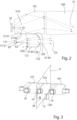
- Figure 1 shows a lighting device 1 for a motor vehicle headlight for generating a light distribution LV, wherein the lighting device has at least one light source 10, a light-transmissive body 100, at least one light coupling element 101 for coupling light emitted by the at least one light source 10 into the light-transmissive body 100 and a projection device 500.
- each of these light sources 10 into a light coupling element 101 light and the light coupling elements 101 couple this light into the light-permeable body 100.
- the projection device 500 and the light-transmitting body 100 are made of the same material and formed in one piece.
- the light-transmissive body 100 has a diaphragm device 103 with a diaphragm edge region 104, wherein the diaphragm device 103 is arranged in the light propagation direction between the at least one light coupling element 101 and the projection device 500.
- the optical body 110 and the body from which the optical body 100 and the projection device 500 are formed are each a solid body, i.e. a body that has no through-openings or opening inclusions.
- the transparent, translucent material from which the bodies are formed has a refractive index greater than that of air.
- the material contains, for example, PMMA (polymethyl methacrylate) or PC (polycarbonate) and is particularly preferably formed from it.
- the bodies can also be made from glass material, in particular inorganic glass material. In the example shown, there are two separate bodies, but the two bodies can also be formed integrally with one another.
- the light S10 emitted by a light source 10 enters the light coupling element 101 and is coupled via this into the light-permeable body 100 and propagates in the light-permeable body 100 as the first light beam S1.
- the first light beam S1 is modified by the aperture device 103 in a manner known to those skilled in the art to form a modified, second light beam S2, which is imaged by the projection device 500 by means of the emerging light beam LL as the light distribution LV to be generated (or as part of the light distribution LV to be generated; in the case of several light sources 10, these together form the light distribution LV).
- the light distribution LV in the form of a low beam distribution is shown by way of example in the Figures 5 and 6 shown.
- the light distribution LV which is generated with the at least one light source 10 and which is, for example, an apron or dipped beam distribution, has a Light-dark boundary HD, wherein the light-dark boundary HD, in particular the shape and position of the light-dark boundary HD, is determined by the diaphragm edge region or a diaphragm edge 104 of the diaphragm device 103.
- the diaphragm device 103 is formed by a first boundary surface 106 and a second boundary surface 105 of the light-permeable body 100.
- the two boundary surfaces 105, 106 converge in the common diaphragm edge 104 or the diaphragm edge region 104.
- the second boundary surface 105 is arranged in front of the second boundary surface 106 in the light propagation direction.
- the second boundary surface is horizontal and approximately parallel to the light propagation direction, while the first boundary surface is transverse to the light propagation direction.
- the lighting device 1 has at least one further light source, in the present case exactly one further light source, the so-called signlight light source 20.
- a further signlight light coupling element 120 assigned to the signlight light source 20 is provided, wherein the signlight light coupling element 120 forms the light S20 emitted by the signlight light source 20 into a third light beam S3 and directs the third light beam S3 onto the first boundary surface 106, so that light rays, in particular essentially all light rays of the third light beam S3, enter the light-permeable body 100 via the first boundary surface 106.
- the signlight light coupling element 120 is preferably located, as shown, on an underside of the at least one light coupling element 101.
- At least a part, preferably all, of the light rays S4 that have re-entered the light-permeable body 100 are projected by the projection optics device 500 as a signlight light beam SL into a region B of the light distribution LV lying above the light-dark boundary HD (see Figure 5 ) and displayed, for example, as a signlight light distribution SV.
- the at least one light source 10 and the signlight light source 20 are arranged such that the main light beam directions X1, X2 of the at least one light source 10 and the signlight light source 20 run parallel to each other.
- the "light propagation direction" corresponds approximately to the direction of the main light emission directions.
- the at least one light source 10 and the signlight light source 20 each comprise one or more light-emitting elements, e.g. one or more LEDs.
- the wording "at least one light source (for generating the light distribution)” means that exactly one such light source, but of course also two or more such light sources can be provided to generate the light distribution.
- the wording "has a signlight light source)" does not exclude the possibility that two or more such signlight light sources can be provided to generate signlight.
- the light rays S2 of the light source 10 reach an upper region of the projection device 500 or an area above a horizontal plane in which an axis of symmetry or the optical axis of the projection device 500 lies in order to generate the light distribution LV.
- these light rays S2 are "inverted" downwards as emerging light rays LL by the corresponding curvature or design of the projection device 500 and form a light distribution LV in the traffic area or on a measuring screen in a lower region, in particular below the 0°-0° line, which is limited at the top by the HD limit.
- the diaphragm edge region or the diaphragm edge 104 lies essentially in a focal line or in a focal surface of the projection device 500, accordingly the diaphragm edge is imaged as a light-dark boundary in the light image LV, which is generated with the light rays of the light bundle S1.
- the signlight light coupling element 120 and the at least one light coupling element 101 are preferably made in one piece, in particular from the same material, and form a transparent body 110.
- the optical body 100 and the light coupling elements are designed in such a way that light propagates in a straight line in them on the one hand, and on the other hand is largely totally reflected when it hits boundary walls and can exit the respective body/element at corresponding exit surfaces or the projection device 500.
- the lighting device 1 comprises according to Figure 1 further an additional light module 200, which is designed, as shown in Figure 6 is shown to generate a segmented additional light distribution FLV which comprises several light segments SEG, whereby the additional light distribution FLV and the light distribution LV together form a high beam distribution when all light segments SEG are activated.
- the additional light distribution FLV adjoins the light distribution LV, ie the apron or low beam distribution, or there is a certain overlap between the two light distributions.
- the additional light module 200 is designed to form a segmented additional light distribution, as described, which consists of laterally adjacent or overlapping light segments SEG, which can be activated and deactivated individually.
- a segmented additional light distribution as described, which consists of laterally adjacent or overlapping light segments SEG, which can be activated and deactivated individually.
- an area in which a vehicle, e.g. of oncoming traffic QFK, is located can remain unlit by switching off the corresponding light segment, so that oncoming traffic QFK is not blinded.
- the high beam light module comprises 200 (see Figure 1 ) a light source 201, e.g. a multichip LED, with which the segmented additional light distribution FLV can be generated in a known manner in cooperation with optical elements 202 - 205 (imaging lenses 202, 204, 205, aperture diaphragm 203).
- a light source 201 e.g. a multichip LED
- optical elements 202 - 205 imaging lenses 202, 204, 205, aperture diaphragm 203.
- the at least one light source 10 in this specific case, the three light sources 10) for generating the light distribution LV and the signlight light source 20 for generating the signlight light distribution SV are activated and the additional light module is deactivated.
- the at least one light source 10 or in this specific case, the three light sources 10) for generating the light distribution LV and the additional light module 200 are activated, whereby this is activated in such a way that all light segments SEG are illuminated, and the signlight light source 20 can also be activated.
- the signlight light source 20 is also deactivated (or at least dimmed).
- the design according to the invention allows the signlight light source to be switched off (or dimmed) in, for example, or partial high beam operation, so that no unwanted scattered radiation can be emitted from the signlight in this operating state.
- the signlight light source In an operating state in which the light distribution, in particular an apron light distribution or a low beam distribution, is generated with the at least one light source, the signlight light source can be switched on so that in addition to the light distribution, a signlight light distribution is generated independently of it.
- the signlight light distribution is generated together with the apron or low beam (i.e., the at least one light source responsible for generating the apron or low beam distribution is also responsible for generating the signlight light distribution) and cannot be switched off independently of it.
- the invention accordingly offers advantages in terms of the glare value, particularly when the lighting device is operated in ADB mode ("Advanced Driving Beam”), in which individual areas or segments of a partial long-distance light distribution can be switched off. Because the sign light is switched off in this operating state, in contrast to the prior art, this cannot cause glare in the masked area or in the masked/switched off segments.
- the reduction of undesirable "residual light" made possible by the invention, particularly in masked areas can increase safety for all road users. increased.
- the sign light can be switched on to make it easier for the driver to read overhead signs, for example.
- the signlight light coupling element 120 contacts the light coupling element 101 in a common contact area or in a common contact surface 130.
- This has the advantage, particularly when the two elements 101, 130 are made of the same material, that the passing light rays are not deflected in their direction of propagation and can therefore also be better controlled in terms of design.
- the contact region or the contact surface 130 is advantageously positioned in such a way, for example in relation to or at a distance from the at least one light source 10, that at least a portion of the light rays S130 coming from the light source 10, which enter the signlight light coupling element 120 via the contact region or the contact surface 130, are totally reflected at a light exit surface 122 of the signlight light coupling element 120.
- This light S130 therefore does not contribute to the light distribution and is deflected into an area where it remains unused and is absorbed, for example.
- the light S130 is deflected to the rear and exits the signlight light coupling element 120 unused.
- the contact area or the contact surface 130 is positioned in such a way, for example in relation to or at a distance from the at least one light source 10, that at least a portion of the light rays S131 coming from the light source 10, which impinge on a light coupling element boundary surface 131 of the light coupling element 101 in front of the contact area or the contact surface 130, are totally reflected at the light coupling element boundary surface 131 into the light coupling element 101 in the direction of the light-permeable body 100.
- the light coupling element boundary surface 131 is the boundary surface on which the contact surface 130 is located. This light S131 can thus contribute to the light distribution, e.g. to the front or low beam distribution.
- the signlight light source 20 is positioned as close as possible to a light coupling surface 121 of the signlight light coupling element 120 in order to be able to capture as much light as possible and to reduce as much as possible rays emanating from the signlight light source 20 that could enter the light coupling element 101 as interference radiation.
- the light coupling surface 121 of the signlight light coupling element 120 is concave and the light exit surface 122 is convex.
- the signlight light coupling element 120 has a focal point F121, wherein the signlight light source 20 is arranged essentially at this focal point F121.
- the light coupling surface 121 is preferably designed to be as concave as possible in order to increase the coupling efficiency by arranging the light source in the concave cavity resulting from this design, preferably as deep as possible, and thus being enclosed by the light coupling surface 121 at least in that angular range in which the light source emits light.
- the scattered light S130 is largely totally reflected and deflected backwards, as already described above.
- the particularly strongly curved design of the light coupling surface 121 enables a light exit surface 122 that is as curved as possible, so that light rays S130 coming from the light coupling element 101, which are coupled into the signlight light coupling element 120, are deflected by total reflection at the light exit surface 122, so that they cannot exit the signlight light coupling element 120 in the direction of light propagation.
- This scattered light is preferably deflected backwards, opposite to the actual direction of light propagation.
- the light emitted by the signlight light source 20 is radiated by the signlight light coupling element 120 directly onto the boundary surface 106.
- direct means that the light is not further influenced on the way to the surface 106 and in particular does not undergo any deflection, i.e. it propagates in a straight line to the boundary surface 106.
- the light coupling element 101 is preferably designed such that the light emitted by the light source 10 and coupled into the light coupling element 101 is formed into the first light beam S1, wherein the light beam S1 is preferably directed into the diaphragm edge region or into a region of the diaphragm edge 104 of the diaphragm device 103.
- the signlight light coupling element 120 illuminates the boundary surface 106 with the third light beam S3 such that a maximum of the illuminance of the light pattern L106 formed on the boundary surface 106 is at a distance greater than zero from the diaphragm edge 104 and/or the light pattern L106 is at a distance greater than zero from the diaphragm edge 104.
- This can be used to create a gap G in the overall light distribution in the traffic area or on a vertical measuring screen in front of the lighting device between the dipped beam distribution and the sign light distribution, as shown in Figure 5 can be recognized.
- light pattern at a distance refers to the edge of the light pattern that encloses the light pattern, with any portion of the edge that lies on the boundary surface 106 being at a distance greater than zero from the aperture edge 104.
- the signlight light coupling element 120 is designed such that the light beam S3 emerging from the signlight light coupling element 120 is expanded in the horizontal direction.
- the signlight light coupling element 120 is designed to be anamorphic or astigmatic, or the light coupling surface 121 and/or the light exit surface 122 are designed in such a way that the light pattern L106 formed on the boundary surface 106 is expanded/distorted in the horizontal direction and thus a wide illumination can be achieved.
- Such a design can be achieved by having a smaller curvature of the signlight light coupling element 120 in the horizontal direction compared to the vertical direction.
- the signlight light coupling element 120 can be designed such that the light rays of the light beam S3 emerging from the signlight light coupling element 120 converge in the vertical direction.
- this makes it possible to efficiently direct light into the desired area, i.e. in particular onto the surface 106 below the edge 104.
- the light exit surface 122 being convex in the vertical direction (i.e. in vertical sections parallel to the main light beam direction X1, X2).
- the light exit surface 122 can also be curved, preferably convex, in particular with a different curvature/radius of curvature than in the vertical direction.
- the boundary surface 106 is convex in the vertical direction (ie in vertical sections), as shown in Figure 4 is shown so that light rays S4.
- the light rays S4 enter the optical body 100 via the boundary surface 106 and reach the projection device 500, from which they are imaged in an area in front of the lighting device 1.
- the boundary surface 106 is preferably located in or substantially in a focal surface or Petzval surface of the projection device 500, so that the area on the boundary surface 106 illuminated by the light rays S4 is projected by the projection device 500 into the traffic space,
- the boundary surface 106 of the translucent body 101 has a light-scattering structure, e.g. a grain.
- an outer surface of the projection device 500 is formed by a groove-shaped structure in a smooth base surface, wherein the grooves forming the groove-shaped structure run in a substantially vertical direction, and wherein preferably two grooves lying next to each other in the horizontal direction are separated by an elevation, in particular one running substantially vertically, which preferably extends over the entire vertical extent of the grooves.
Landscapes
- Engineering & Computer Science (AREA)
- General Engineering & Computer Science (AREA)
- Physics & Mathematics (AREA)
- Microelectronics & Electronic Packaging (AREA)
- Optics & Photonics (AREA)
- Non-Portable Lighting Devices Or Systems Thereof (AREA)
- Lighting Device Outwards From Vehicle And Optical Signal (AREA)
Priority Applications (5)
| Application Number | Priority Date | Filing Date | Title |
|---|---|---|---|
| EP23173075.5A EP4462014A1 (fr) | 2023-05-12 | 2023-05-12 | Dispositif d'éclairage pour un phare de véhicule automobile et phare de véhicule automobile |
| JP2024070615A JP2024163857A (ja) | 2023-05-12 | 2024-04-24 | 自動車投光器用の照射装置並びに自動車投光器 |
| KR1020240055834A KR20240164402A (ko) | 2023-05-12 | 2024-04-26 | 자동차 헤드라이트용 조명 장치 및 자동차 헤드라이트 |
| US18/655,622 US12584602B2 (en) | 2023-05-12 | 2024-05-06 | Illumination device for motor vehicle headlight and motor vehicle headlight |
| CN202410573234.9A CN118935283A (zh) | 2023-05-12 | 2024-05-10 | 用于机动车前照灯的照明设备以及机动车前照灯 |
Applications Claiming Priority (1)
| Application Number | Priority Date | Filing Date | Title |
|---|---|---|---|
| EP23173075.5A EP4462014A1 (fr) | 2023-05-12 | 2023-05-12 | Dispositif d'éclairage pour un phare de véhicule automobile et phare de véhicule automobile |
Publications (1)
| Publication Number | Publication Date |
|---|---|
| EP4462014A1 true EP4462014A1 (fr) | 2024-11-13 |
Family
ID=86378627
Family Applications (1)
| Application Number | Title | Priority Date | Filing Date |
|---|---|---|---|
| EP23173075.5A Pending EP4462014A1 (fr) | 2023-05-12 | 2023-05-12 | Dispositif d'éclairage pour un phare de véhicule automobile et phare de véhicule automobile |
Country Status (5)
| Country | Link |
|---|---|
| US (1) | US12584602B2 (fr) |
| EP (1) | EP4462014A1 (fr) |
| JP (1) | JP2024163857A (fr) |
| KR (1) | KR20240164402A (fr) |
| CN (1) | CN118935283A (fr) |
Citations (5)
| Publication number | Priority date | Publication date | Assignee | Title |
|---|---|---|---|---|
| DE102011118270A1 (de) * | 2010-12-03 | 2012-06-06 | Docter Optics Gmbh | Fahrzeugscheinwerfer |
| WO2020064978A1 (fr) * | 2018-09-27 | 2020-04-02 | Valeo Vision | Élément optiquae, module optique et véhicule |
| WO2021246065A1 (fr) * | 2020-06-02 | 2021-12-09 | ミネベアミツミ株式会社 | Dispositif d'éclairage |
| WO2022100057A1 (fr) * | 2020-11-16 | 2022-05-19 | 华域视觉科技(上海)有限公司 | Dispositif optique pour phare de véhicule, dispositif d'éclairage de véhicule et véhicule |
| EP4137744A1 (fr) * | 2020-07-02 | 2023-02-22 | Hasco Vision Technology Co., Ltd. | Unité optique de lampe de véhicule, module de lampe de véhicule et véhicule |
Family Cites Families (8)
| Publication number | Priority date | Publication date | Assignee | Title |
|---|---|---|---|---|
| JP5511347B2 (ja) * | 2009-12-10 | 2014-06-04 | 株式会社小糸製作所 | 発光モジュールおよび車両用灯具 |
| JP6410341B2 (ja) * | 2014-05-23 | 2018-10-24 | 株式会社小糸製作所 | 車両用前照灯 |
| WO2016162921A1 (fr) * | 2015-04-06 | 2016-10-13 | 三菱電機株式会社 | Source de lumière de phare et phare |
| AT518098B1 (de) * | 2015-12-17 | 2017-11-15 | Zkw Group Gmbh | Zusatzscheinwerfer für Fahrzeuge sowie Scheinwerfersystem |
| JP7055563B2 (ja) * | 2018-03-28 | 2022-04-18 | ダイハツ工業株式会社 | 配光制御装置 |
| KR102558734B1 (ko) * | 2018-12-26 | 2023-07-25 | 에스엘 주식회사 | 차량용 램프 |
| JP7354570B2 (ja) * | 2019-03-28 | 2023-10-03 | 市光工業株式会社 | 車両用灯具 |
| JP7608975B2 (ja) * | 2021-06-11 | 2025-01-07 | 市光工業株式会社 | 車両用灯具ユニット、車両用灯具装置 |
-
2023
- 2023-05-12 EP EP23173075.5A patent/EP4462014A1/fr active Pending
-
2024
- 2024-04-24 JP JP2024070615A patent/JP2024163857A/ja active Pending
- 2024-04-26 KR KR1020240055834A patent/KR20240164402A/ko active Pending
- 2024-05-06 US US18/655,622 patent/US12584602B2/en active Active
- 2024-05-10 CN CN202410573234.9A patent/CN118935283A/zh active Pending
Patent Citations (5)
| Publication number | Priority date | Publication date | Assignee | Title |
|---|---|---|---|---|
| DE102011118270A1 (de) * | 2010-12-03 | 2012-06-06 | Docter Optics Gmbh | Fahrzeugscheinwerfer |
| WO2020064978A1 (fr) * | 2018-09-27 | 2020-04-02 | Valeo Vision | Élément optiquae, module optique et véhicule |
| WO2021246065A1 (fr) * | 2020-06-02 | 2021-12-09 | ミネベアミツミ株式会社 | Dispositif d'éclairage |
| EP4137744A1 (fr) * | 2020-07-02 | 2023-02-22 | Hasco Vision Technology Co., Ltd. | Unité optique de lampe de véhicule, module de lampe de véhicule et véhicule |
| WO2022100057A1 (fr) * | 2020-11-16 | 2022-05-19 | 华域视觉科技(上海)有限公司 | Dispositif optique pour phare de véhicule, dispositif d'éclairage de véhicule et véhicule |
Also Published As
| Publication number | Publication date |
|---|---|
| JP2024163857A (ja) | 2024-11-22 |
| KR20240164402A (ko) | 2024-11-19 |
| CN118935283A (zh) | 2024-11-12 |
| US20240377043A1 (en) | 2024-11-14 |
| US12584602B2 (en) | 2026-03-24 |
Similar Documents
| Publication | Publication Date | Title |
|---|---|---|
| EP3343091B1 (fr) | Module d'éclairage de phare de véhicule automobile | |
| AT518552B1 (de) | Beleuchtungseinheit für einen Kraftfahrzeugscheinwerfer zum Erzeugen von zumindest zwei Lichtverteilungen | |
| EP2799761B1 (fr) | Module d'éclairage de phare de véhicule automobile | |
| EP2431657B1 (fr) | Module de réflecteur d'un phare de véhicule automobile | |
| AT518551B1 (de) | Kraftfahrzeugbeleuchtungsvorrichtung | |
| DE60302708T2 (de) | Kfz-Scheinwerfer nach dem Projektionsprinzip mit einer sekundären Lichtquelle | |
| DE102009021046A1 (de) | Fahrzeugscheinwerfer | |
| EP2984396B1 (fr) | Unité lumineuse dotée d'un cache pourvu d'au moins une fenêtre optique | |
| DE202015010030U1 (de) | Leuchmodul zur Beleuchtung und/oder Signalisierung eines Kraftfahrzeugs | |
| DE112012006849T5 (de) | Lichtquelle für einen Scheinwerfer und Scheinwerfer | |
| EP2602539A1 (fr) | Module d'éclairage pour un phare de véhicule automobile | |
| EP4025827B1 (fr) | Dispositif d'éclairage pour un phare de véhicule automobile | |
| DE102009037698A1 (de) | Fahrzeugbeleuchtungseinheit und Fahrzeugleuchte | |
| EP2719940A2 (fr) | Module d'éclairage | |
| EP3699486B1 (fr) | Phare pourvu d'une pluralité de sources lumineuses à semi-conducteurs et d'un champ optique primaire en une pièce | |
| WO2019233953A1 (fr) | Phare de véhicule à moteur comprenant au moins deux modules d'éclairage | |
| EP3388734A1 (fr) | Unité optique primaire pour un module d'éclairage de phare de véhicule | |
| EP3671016A1 (fr) | Dispositif d'éclairage pour un phare de véhicule automobile ainsi que phare de véhicule automobile | |
| WO2014165890A1 (fr) | Unité d'éclairage pour projecteur de véhicule | |
| DE102012215124B4 (de) | Beleuchtungseinrichtung mit mehreren Lichtquellen und Lichtleitkörpern sowie einem Reflektor | |
| EP4506616B1 (fr) | Dispositif d'éclairage pour un phare de véhicule automobile et phare de véhicule automobile | |
| EP4462014A1 (fr) | Dispositif d'éclairage pour un phare de véhicule automobile et phare de véhicule automobile | |
| DE102016122188A1 (de) | Lichtvorrichtung, insbesondere ein Projektorsystem für einen Scheinwerfer für Kraftfahrzeuge | |
| EP4545845B1 (fr) | Dispositif d'éclairage pour un phare de véhicule automobile et phare de véhicule automobile | |
| EP2052284B1 (fr) | Phare de véhicule |
Legal Events
| Date | Code | Title | Description |
|---|---|---|---|
| PUAI | Public reference made under article 153(3) epc to a published international application that has entered the european phase |
Free format text: ORIGINAL CODE: 0009012 |
|
| STAA | Information on the status of an ep patent application or granted ep patent |
Free format text: STATUS: THE APPLICATION HAS BEEN PUBLISHED |
|
| AK | Designated contracting states |
Kind code of ref document: A1 Designated state(s): AL AT BE BG CH CY CZ DE DK EE ES FI FR GB GR HR HU IE IS IT LI LT LU LV MC ME MK MT NL NO PL PT RO RS SE SI SK SM TR |
|
| STAA | Information on the status of an ep patent application or granted ep patent |
Free format text: STATUS: REQUEST FOR EXAMINATION WAS MADE |
|
| 17P | Request for examination filed |
Effective date: 20250509 |