EP4462068A1 - Arme à répétition - Google Patents
Arme à répétition Download PDFInfo
- Publication number
- EP4462068A1 EP4462068A1 EP24161088.0A EP24161088A EP4462068A1 EP 4462068 A1 EP4462068 A1 EP 4462068A1 EP 24161088 A EP24161088 A EP 24161088A EP 4462068 A1 EP4462068 A1 EP 4462068A1
- Authority
- EP
- European Patent Office
- Prior art keywords
- bolt
- slide
- fore
- handle
- repeating rifle
- Prior art date
- Legal status (The legal status is an assumption and is not a legal conclusion. Google has not performed a legal analysis and makes no representation as to the accuracy of the status listed.)
- Granted
Links
Images





Classifications
-
- F—MECHANICAL ENGINEERING; LIGHTING; HEATING; WEAPONS; BLASTING
- F41—WEAPONS
- F41C—SMALLARMS, e.g. PISTOLS, RIFLES; ACCESSORIES THEREFOR
- F41C7/00—Shoulder-fired smallarms, e.g. rifles, carbines, shotguns
- F41C7/02—Pump-action guns, i.e. guns having a reciprocating handgrip beneath the barrel for loading or cocking
-
- F—MECHANICAL ENGINEERING; LIGHTING; HEATING; WEAPONS; BLASTING
- F41—WEAPONS
- F41A—FUNCTIONAL FEATURES OR DETAILS COMMON TO BOTH SMALLARMS AND ORDNANCE, e.g. CANNONS; MOUNTINGS FOR SMALLARMS OR ORDNANCE
- F41A3/00—Breech mechanisms, e.g. locks
- F41A3/12—Bolt action, i.e. the main breech opening movement being parallel to the barrel axis
- F41A3/14—Rigid bolt locks, i.e. having locking elements rigidly mounted on the bolt or bolt handle and on the barrel or breech-housing respectively
- F41A3/16—Rigid bolt locks, i.e. having locking elements rigidly mounted on the bolt or bolt handle and on the barrel or breech-housing respectively the locking elements effecting a rotary movement about the barrel axis, e.g. rotating cylinder bolt locks
- F41A3/18—Rigid bolt locks, i.e. having locking elements rigidly mounted on the bolt or bolt handle and on the barrel or breech-housing respectively the locking elements effecting a rotary movement about the barrel axis, e.g. rotating cylinder bolt locks hand-operated
- F41A3/20—Straight-pull operated bolt locks, i.e. the operating hand effecting only a straight movement parallel to the barrel axis
-
- F—MECHANICAL ENGINEERING; LIGHTING; HEATING; WEAPONS; BLASTING
- F41—WEAPONS
- F41A—FUNCTIONAL FEATURES OR DETAILS COMMON TO BOTH SMALLARMS AND ORDNANCE, e.g. CANNONS; MOUNTINGS FOR SMALLARMS OR ORDNANCE
- F41A3/00—Breech mechanisms, e.g. locks
- F41A3/64—Mounting of breech-blocks; Accessories for breech-blocks or breech-block mountings
- F41A3/72—Operating handles or levers; Mounting thereof in breech-blocks or bolts
Definitions
- the present invention relates to a repeating rifle, in particular a repeating rifle, which is designed as a straight-pull repeater, comprising a fore-end and a bolt handle.
- handguns pistols and revolvers
- rifles also known as small arms (rifles and shotguns)
- small arms rifles and shotguns
- bolts for rifles The basic purpose of bolts for rifles is to mechanically and securely close the barrel, which is open at the back for loading, when the weapon is fired.
- rigid locking bolts were and are the most common locking technology for rifles for civilian, official and sporting use, and are usually operated by hand.
- the bayonet-like and manually rotating cylinder bolt has become the norm. This not only locks the barrel (albeit often indirectly via the barrel-supporting system housing), but also serves, with its linear movement component, to eject the fired cartridge case and feed a new cartridge from the cartridge magazine. This process is called repeating, and consequently the corresponding rifles for ball ammunition are called repeating rifles, and the corresponding design for shotgun ammunition is called repeating shotguns.
- the main disadvantage of this design is the need to raise the weapon for reloading when firing a follow-up shot while hunting or shooting while lying down, so that the forearm can be oscillated linearly with the guiding hand.
- the straight-pull repeater model R93 from the manufacturer Blaser was developed based on the then very successful straight-pull repeater model R93 from DE 43 05 700 C1 with a connecting rod-like retrofit kit according to the documents DE 200 00 158 U1 and DE 201 00 014 U1 tried to use the straight-pull repeater as a pump-action repeater if necessary.
- the US 2,422,532 A , the GB 132,889 A , the US 2019/0212081 A1 and the US 2,832,165 A reveal repeating rifles that can be operated either with the fore-end or with the bolt handle.
- the aim of the invention is to overcome the described disadvantages of the prior art and to create a repeating rifle, in particular a repeating rifle, which is versatile and ergonomic to operate.
- the invention enables the shooter to operate one and the same repeating rifle, depending on the specific situation, using the repeating mechanism that is more advantageous in that situation, particularly from an ergonomic point of view.
- switching between operation with the forearm and operation with the bolt handle takes place without tools using at least one operating handle arranged on or in the repeating rifle. Switching between the two operating modes is therefore very quick and easy for the shooter. It is particularly advantageous if an operating handle is attached to both sides (for left- and right-handed shooters) on or in the forearm or housing of the repeating rifle.
- the specific design of the operating handle can be based on the design that has been tried and tested millions of times and is used, for example, in switches on hand drills that switch from clockwise to anti-clockwise rotation.
- the at least one operating handle can be designed as a push button switch, toggle switch, rocker switch, rotary switch or pendulum switch.
- the at least one actuating handle has a two-stage switching mechanism with a first switching state and a second switching state (in their stop-related end positions).
- the switching mechanism can be completely or partially covered by the forearm.
- the straight-pull repeater In the first switching state (ie in one position of the operating handle) the straight-pull repeater can be operated as a forearm repeater, while in the second switching state (ie in the other position of the operating handle) the operation - with the forearm fixed axially - is carried out via the bolt handle.
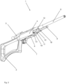
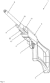
- a repeating rifle designated 1 is shown according to a first embodiment of the invention, the linear bolt (with the bolt head located in the firing direction) of which allows operation as a straight-pull repeater.
- the bolt which is guided longitudinally in a housing 4 arranged between the forearm 2 and the buttstock 3, is provided with a bolt rod 5, at the free end of which a grip ball is attached for comfortable repeating.
- a cartridge magazine 6 and a trigger assembly 7 are inserted in the housing 4, and a barrel 8 is arranged on the front end of the housing.
- the forearm 2 is penetrated transversely to the barrel axis by an axially movable and rotationally fixed actuating handle 13 designed as a slide switch 13, the two front sides of which are mirror-symmetrically opposite one another and can be operated as push buttons (with left and right end positions). With these, the repeating rifle 1 can be switched between the two operating modes “repeating using the bolt handle” and “repeating using the forearm”.
- the slide 10 is provided with a preferably square longitudinal opening 18. Perpendicular to this, this has a shaft-like transverse opening 19 for the rotationally fixed longitudinal guide of the slide switch 13.
- the slide 10 is provided on its two side surfaces with mirror-symmetrical guide grooves 11 (or longitudinal openings) for two actuating rods 12 (preferably with a rectangular cross-section), which are axially fixedly coupled to the linear lock.
- the at least one actuating rod 12 must be longitudinally guided only in the housing 4 or both in the housing 4 and in or on the slide 10.
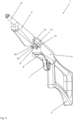
- Fig. 3 shows the polygonal profiled longitudinal guide 9, as the square bar mentioned above, with the slide 10 removed. It is preferably arranged as a cantilever arm fixed to the housing 4 below the barrel 8 (which is also fixed to the housing 4) and essentially parallel to it. Since the slide-forearm assembly 2, 10 is arranged on it (longitudinally movable) and is not in mechanical contact with the barrel 8, the latter can swing freely, promoting shooting precision.
- the straight pull lock is guided longitudinally in the housing 4 and is axially fixedly coupled to at least one of the two actuating rods 12 - preferably in a form-fitting manner.
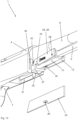
- Fig. 3 to Fig. 6 reveal the compact and user-friendly switching mechanism, whose slide switch 13 can be operated by pressing a button on its left or right front side either (according to Fig. 4 ) with the square rod 9 or the operating rod(s) 12 (according to Fig. 6 ) comes into action.
- the latter is/are 12 after Fig. 5 with at least one gap-like cutout 14, and the square bar 9 with a vertical transverse groove 15.
- the slide switch 13 is Fig. 5 provided with a cuboid-shaped locking projection 16 which, on its side facing away from the square bar 9, merges into a groove-like locking recess 17 which terminates with a frontal cross-section in the outline of the locking projection 16.
- the locking projection 16 is offset on its side facing the square bar 9.
- the slide switch 13 has a flat cross-section, which Fig. 1 push-button-like protrudes transversely from the forearm 2. This shape of the slide switch 13 provides in both directions of movement the axial locking of the slide 10 and thus of the forearm 2 locking lugs 20, 21 on both sides of the locking projection 16 (see Fig. 5 ).
- Fig. 7 shows this mode of operation with the shutter closed with the slide 10 and Fig. 8 with the attached forearm 2 in its front end position.
- the market accepts the hand-wide "gap" between the forearm 2 and the housing 4, even if it is concealed here and there with U-shaped forearm extensions that protrude backwards.
- the present invention counteracts this in the probably predominantly used operating mode with bolt handle 5:
- Fig. 1 and Fig. 2 The carriage 10 is in its Slide switch 13 with the longitudinal guide 9 locked, rear end position, whereby the fore-end 2 merges elegantly flush into the housing 4.
- the slide switch 13 is Fig. 5 - as mentioned - offset on the groove-side locking lug 20 and extends from here with its flat cross-section to its front side. This cross-section allows easy assembly with the bolt open through the entire rifle 1.
- the slide switch 13 first passes through a corresponding shaft in the fore-end 2, then penetrates the cross-section-equal transverse opening 19 of the slide 13, before its front side emerges from a shaft of smaller cross-section in the fore-end 2.
- This end position is formed mechanically elegantly by the stop of the groove-side locking lug 20 on the groove base of the vertical transverse groove 15 and thus ensures the maximum form fit between the longitudinal guide 9 and the slide switch 13 and thus with the slide 10 and consequently also with the fore-end 2 attached to it.
- the slide switch 13 In both end positions, the slide switch 13 is secured in position by a spring catch and can be opened laterally - for example with a Screwdriver blade - can be pushed out of the forearm 2.
- the forearm-slide assembly 2, 10 can then be pulled off in the direction of fire - e.g. for cleaning the weapon.
- a round pin can be arranged on at least one of the two end faces of the locking projection 16, the axis of which extends in the direction of movement of the slide switch 13.
- One of these engages in a corresponding transverse bore in the square rod 9 and the other in a through-bore in the actuating rod(s) 12, which can be produced economically as a punched hole.
- At least one raised shape e.g. folded sheet metal tab
- the sheet metal strip(s) 12 which can be produced economically by forming can engage or disengage in a form-fitting manner with a corresponding recess in the locking projection 16.
- the slide switch 13 described above is designed as an axially fixed and rotatable switching shaft.
- This is axially fixed and rotatably mounted in a transverse bore - in a similar position to the transverse opening 19 - of the slide 10 and corresponds to recesses in the actuating rod(s) 12 and the square rod 9 that are congruent transversely to the barrel axis - preferably semicircular-cylindrical, but also prismatic or V-shaped.
- the lower side surfaces 22 of said rods 12 and the lower side surface 23 of the square rod 9 constructively form a plane in which (or in a plane parallel to) the axis of said switching shaft lies.
- the switching shaft is now engaged with the two actuating rods 12 and is decoupled from the square rod 9: This creates an axial connection between the slide 10 and the actuating rods 12 and releases it from the square rod 9.
- the rifle 1 can now be operated as a pump-action rifle, with the fore-end 2 driving the linear bolt (in the same direction) and the bolt rod attached to it moving back and forth with it uselessly.
- the slide switch 13 or the switching shaft or a pivoting mechanism are arranged inside the weapon so that they are not visible from the outside and cannot be operated incorrectly and can be switched manually, for example after removing the cartridge magazine 6 through the then free magazine slot.
- a mirror-symmetrical and fork-shaped swivel bolt 24 (which can be regarded as a pendulum switch 13) that can be produced economically as a stamped and bent part is guided with its two bolt flanks 26 on bearing pins 28 arranged on both sides and also mirror-symmetrically on the slide 10 so as to be pivotable about the pin axis transversely to the repeating rifle 1.
- the two flanks 26 are provided with two bearing bores 29 with the same axis.
- each of the two flanks 26 has a gap 33, 34 in the circumferential direction on both sides, whereby one can engage or disengage with, for example, a sheet metal tab 35 of the actuating rod(s) 12 and the other with a projection or a recess of the buttstock-housing-barrel-longitudinal guide assembly 3, 4, 8, 9. Fig.
- a locking bolt 30 which protrudes transversely from the square bar 9 in a mirror-symmetrical manner on both sides, the two ends of which engage laterally with the two gaps 33 of the swivel bolt 24, whereby the rear flanks of the gaps 33 preferably rest against the rear lateral surfaces of the locking bolts 30 and the slide 10 (including the fore-end 2) preferably strikes the housing 4 in the shooter's direction.
- the slide 10 which is preferably designed as a square tube, is axially fixed to the buttstock-housing-barrel-square bar assembly 3, 4, 8, 9 and thus also the fore-end 2 which is fixed to it or possibly made in one piece with it. This provides the operating mode with bolt handle 5.
- both actuating rods 12 which are coupled axially to the lock in a mirror-symmetrical manner - only the left one is shown so that the swivel bolt 24 is visible - oscillate through their shafts 32.
- the sheet metal tabs 35 which are bent inwards in a mirror-symmetrical manner from both actuating rods 12 (and formed from their undersides 22), pass unhindered over the undersides of both bolt flanks 26.
- the two ends of the locking bolt 30 which can be designed as welded bolts (mirror-symmetrically welded onto the square bar 9) - with their two corresponding gaps 33 and the two metal tabs 35 with their two corresponding gaps 34 in the locking flank 26 are mirror-symmetrically opposite each other.
- the The swivel bolt 24 can be switched between the two operating modes manually and without tools.
- an operating finger reaches through the open magazine slot 31 to Fig. 9 and engages under a handling lip 25, which is arranged on a locking bridge 27 connecting both locking flanks 26.
- the pendulum switch 13 jumps from its angular position into Fig.
- the operating mode is a pump-action repeater with the following force flow: Forearm 2 --> Slide 10 --> Bearing pin 28 --> Bearing holes 29 --> Bolt flanks 26 --> Gaps 34 --> Sheet metal tabs 35 --> Operating rods 12 --> Bolt.
- the swivel bolt 24 To switch to the previous operating mode with bolt handle 5, with the bolt open and the cartridge magazine 6 removed, the swivel bolt 24 must be pressed back into its original end position through the magazine shaft 31 by pressing the bolt bridge 27 with your finger, in which the two gaps 33 of the two flanks 26 again synchronously engage around the two bolt pin ends 30.
- the swivel bolt 24 snaps tactilely into both end positions, in which it remains securely in place.
- a catch which consists of at least one catch pin 38 arranged transversely on the slide 10, on the outer surface of which a ball rests, which is acted upon by a catch pressure spring 37.
- All catch elements are arranged in a respective and preferably congruent opening 36 of the latch flanks 26, which is covered on the inside by the slide 10 and on the outside by the respective actuating rod 12. They are thus securely housed in a sandwich-like manner in the latch flank(s) 26 between the actuating rod(s) 12 and the side surface(s) of the slide 10.
- the pendulum switch 24 is mechanically understood as a single-armed lever with a pivot axis around the axis of its bearing pin 28. To operate it, the locking bridge 27 or to pull the handling lip 25 (up). Ergonomically, it can be advantageous if the switch 13, 24 can only be operated by pressure. To do this, the pendulum switch 24 would have to become a rocker switch 13. This can be achieved by extending at least one bolt flank 26 in the firing direction, which would create a two-armed lever, both ends of which could be operated by manual pressure through the fore-end 2.
- Another design comprises a swivel mechanism also arranged on the slide 10, the rotation axis of which extends essentially parallel to the barrel axis and which is axially fixedly mounted on the slide 10 or fore-end 2.
- the end of the swivel mechanism accessible through the magazine well has a claw coupling designed as a rocker switch, which in one of its angular end positions engages or disengages with the housing-barrel longitudinal guide assembly 4, 8, 9 and in its other angular end position engages or disengages with the bolt actuating rod(s) assembly 12.
- the fore-end 2 is decoupled from the slide 10 and guided separately on the longitudinal guide 9 for axial movement. Both elements are positively coupled via a reversing gear so that they move axially in opposite directions.
- This design takes aesthetic aspects into account when operated as a fore-end repeater, since when the bolt is closed - i.e. when the weapon is ready to fire - the fore-end 2 merges flush and "without gaps" into the housing 4.
- Another embodiment also not shown graphically, includes the so-called "bullpup" design.
- This is a short design of rifles in which the classic buttstock 2 is omitted and is replaced by the housing 4 with an ergonomically designed shoulder rest.
- the subject matter of the invention is predestined for this short design, since the repetition - by means of the fore-end 2 or bolt handle 5 - takes place ergonomically comfortably in the front area of the weapon 1 using the operating rod(s) 12, while the operating rod(s) 12 ensure the other weapon functions - e.g. loading by means of the bolt movement and cocking the lock - in the housing 4 like a transfer rail.
Landscapes
- Engineering & Computer Science (AREA)
- General Engineering & Computer Science (AREA)
- Toys (AREA)
- Control Of Driving Devices And Active Controlling Of Vehicle (AREA)
- Mechanical Control Devices (AREA)
Applications Claiming Priority (1)
| Application Number | Priority Date | Filing Date | Title |
|---|---|---|---|
| DE102023112184.7A DE102023112184B3 (de) | 2023-05-09 | 2023-05-09 | Repetiergewehr |
Publications (3)
| Publication Number | Publication Date |
|---|---|
| EP4462068A1 true EP4462068A1 (fr) | 2024-11-13 |
| EP4462068C0 EP4462068C0 (fr) | 2025-08-06 |
| EP4462068B1 EP4462068B1 (fr) | 2025-08-06 |
Family
ID=90246646
Family Applications (1)
| Application Number | Title | Priority Date | Filing Date |
|---|---|---|---|
| EP24161088.0A Active EP4462068B1 (fr) | 2023-05-09 | 2024-03-04 | Arme à répétition |
Country Status (3)
| Country | Link |
|---|---|
| US (1) | US12480739B2 (fr) |
| EP (1) | EP4462068B1 (fr) |
| DE (1) | DE102023112184B3 (fr) |
Citations (13)
| Publication number | Priority date | Publication date | Assignee | Title |
|---|---|---|---|---|
| DE106939C (fr) | ||||
| US398063A (en) | 1889-02-19 | mauser | ||
| GB132889A (en) | 1918-09-27 | 1919-09-29 | Improvements in or relating to bolt mechanism for small arms | |
| US2422532A (en) | 1943-12-11 | 1947-06-17 | Dehm Edward | Bolt-actuated cartridge feeding means for rifles |
| US2499878A (en) * | 1948-04-08 | 1950-03-07 | Jerry W Raymond | Slide action attachment for shotguns and rifles |
| US2832165A (en) | 1955-08-25 | 1958-04-29 | Jessie T Ivy | Bolt turning attachment for rifle |
| DE4305700C1 (de) | 1993-02-25 | 1994-10-27 | Blaser Horst Jagdwaffen | Verschluß für eine Schußwaffe, insbesondere ein Repetiergewehr |
| EP0692696B1 (fr) | 1994-07-13 | 1999-07-28 | Browning S.A. | Arme à feu à pompe |
| DE20000158U1 (de) | 2000-01-07 | 2000-03-30 | Engel, Heinz-Eckhard, Dr., Glurns | Repetierbüchse |
| FR2855873A1 (fr) * | 2003-06-06 | 2004-12-10 | Luc De Bruyn Ets | Fusil a repetition |
| US7467581B2 (en) | 2005-10-25 | 2008-12-23 | Browning International, Societe Anonyme | Semi-automatic rifle |
| US20140059910A1 (en) * | 2012-08-20 | 2014-03-06 | Ra Brands, L.L.C. | Bolt assembly for firearms |
| US20190212081A1 (en) | 2018-01-09 | 2019-07-11 | Sturm, Ruger & Company, Inc. | Pump action firearm with slide lock mechanism |
Family Cites Families (12)
| Publication number | Priority date | Publication date | Assignee | Title |
|---|---|---|---|---|
| CH1613A (de) * | 1889-09-19 | 1890-02-28 | Oberst Schmidt Rudolf | Verschluss und Repetirsystem für Gewehre |
| CH7667A (de) * | 1893-10-03 | 1894-05-31 | Leclercq & Hirt | Geradezugverschluß-Gewehr |
| AT2715B (fr) * | 1899-09-04 | 1900-11-26 | Ferdinand Ritter Vo Mannlicher | |
| AT71620B (de) * | 1913-12-09 | 1916-06-10 | Paul Mauser Dr Ing | Drehwarzenverschluß für Handfeuerwaffen. |
| US1613205A (en) * | 1924-05-03 | 1927-01-04 | Soncini Cesare | Automatic firearm with recoiling barrel |
| US2214071A (en) * | 1938-12-01 | 1940-09-10 | Western Cartridge Co | Bolt-action firearm |
| BE527954A (fr) | 1953-04-08 | |||
| US6530306B1 (en) * | 2000-04-28 | 2003-03-11 | Gary Kenneth La Fleur | Closed bolt firing delayed blowback automatic handgun firearm |
| DE202006000661U1 (de) | 2005-01-31 | 2006-05-24 | Edag Engineering + Design Ag | Bördelvorrichtung mit nachgiebiger Stützrolle |
| DE202006006616U1 (de) * | 2006-04-23 | 2007-09-06 | Engel, Heinz-Eckhard, Dr. | Vorderschaftrepetierer |
| US8832478B2 (en) | 2011-10-27 | 2014-09-09 | Intel Corporation | Enabling a non-core domain to control memory bandwidth in a processor |
| US9016187B2 (en) * | 2013-10-02 | 2015-04-28 | Smith & Wesson Corp. | Pump action rifle and action lock mechanism |
-
2023
- 2023-05-09 DE DE102023112184.7A patent/DE102023112184B3/de active Active
-
2024
- 2024-03-04 EP EP24161088.0A patent/EP4462068B1/fr active Active
- 2024-04-10 US US18/631,552 patent/US12480739B2/en active Active
Patent Citations (14)
| Publication number | Priority date | Publication date | Assignee | Title |
|---|---|---|---|---|
| DE106939C (fr) | ||||
| US398063A (en) | 1889-02-19 | mauser | ||
| GB132889A (en) | 1918-09-27 | 1919-09-29 | Improvements in or relating to bolt mechanism for small arms | |
| US2422532A (en) | 1943-12-11 | 1947-06-17 | Dehm Edward | Bolt-actuated cartridge feeding means for rifles |
| US2499878A (en) * | 1948-04-08 | 1950-03-07 | Jerry W Raymond | Slide action attachment for shotguns and rifles |
| US2832165A (en) | 1955-08-25 | 1958-04-29 | Jessie T Ivy | Bolt turning attachment for rifle |
| DE4305700C1 (de) | 1993-02-25 | 1994-10-27 | Blaser Horst Jagdwaffen | Verschluß für eine Schußwaffe, insbesondere ein Repetiergewehr |
| EP0692696B1 (fr) | 1994-07-13 | 1999-07-28 | Browning S.A. | Arme à feu à pompe |
| DE20000158U1 (de) | 2000-01-07 | 2000-03-30 | Engel, Heinz-Eckhard, Dr., Glurns | Repetierbüchse |
| DE20100014U1 (de) | 2000-01-07 | 2001-04-05 | Engel, Heinz-Eckhard, Dr., Glurns | Repetierbüchse |
| FR2855873A1 (fr) * | 2003-06-06 | 2004-12-10 | Luc De Bruyn Ets | Fusil a repetition |
| US7467581B2 (en) | 2005-10-25 | 2008-12-23 | Browning International, Societe Anonyme | Semi-automatic rifle |
| US20140059910A1 (en) * | 2012-08-20 | 2014-03-06 | Ra Brands, L.L.C. | Bolt assembly for firearms |
| US20190212081A1 (en) | 2018-01-09 | 2019-07-11 | Sturm, Ruger & Company, Inc. | Pump action firearm with slide lock mechanism |
Also Published As
| Publication number | Publication date |
|---|---|
| US12480739B2 (en) | 2025-11-25 |
| EP4462068C0 (fr) | 2025-08-06 |
| DE102023112184B3 (de) | 2024-04-04 |
| EP4462068B1 (fr) | 2025-08-06 |
| US20240377156A1 (en) | 2024-11-14 |
Similar Documents
| Publication | Publication Date | Title |
|---|---|---|
| EP1147359B1 (fr) | Culasse pour arme a feu de poing | |
| EP3011253B1 (fr) | Kit de conversion d'arme à feu ainsi que procédé de conversion d'une arme à feu | |
| EP1257775B1 (fr) | Arme de poing a feu a repetition avec blocage de fermeture liberable | |
| EP1518086B1 (fr) | Mitraillette | |
| DE19903321B4 (de) | Ladehebelanordnung für eine Handfeuerwaffe | |
| EP4290173B1 (fr) | Carcasse pour une arme à feu à chargement automatique, ainsi que arme à feu à chargement automatique équipée d'une telle carcasse | |
| DE69220755T2 (de) | Feuerwaffe mit zwei Läufen und Zylinderverschluss | |
| DE3435809C2 (fr) | ||
| EP0416642A2 (fr) | Arme à feu | |
| DE19600459A1 (de) | Verschluß für eine Schußwaffe | |
| DE20319451U1 (de) | Schußwaffe | |
| EP1682844B1 (fr) | Levier de verrouillage et arme automatique pourvu de ce levier de verrouillage | |
| DE102021127979B4 (de) | Verschlusssperrenvorrichtung für schusswaffen | |
| WO2023174929A1 (fr) | Tête de culasse d'arme de chasse et de sport | |
| DE102017128911B4 (de) | Selbstladepistole | |
| EP4038333B1 (fr) | Carabine dotée d'une poignée de charge | |
| DE102023112184B3 (de) | Repetiergewehr | |
| DE10041945A1 (de) | Vorrichtung für eine Handfeuerwaffe | |
| DE10008979B4 (de) | Mehrlade-Handfeuerwaffe mit lösbarer Verschlußsperre | |
| DE10051708B4 (de) | Selbstladepistole | |
| DE203665C (fr) | ||
| DE223197C (fr) | ||
| DE128941C (fr) | ||
| EP1535016A1 (fr) | Ensemble ejecteur de cartouches | |
| DE202005008397U1 (de) | Verschlußvorrichtung für eine Schußwaffe |
Legal Events
| Date | Code | Title | Description |
|---|---|---|---|
| PUAI | Public reference made under article 153(3) epc to a published international application that has entered the european phase |
Free format text: ORIGINAL CODE: 0009012 |
|
| STAA | Information on the status of an ep patent application or granted ep patent |
Free format text: STATUS: REQUEST FOR EXAMINATION WAS MADE |
|
| 17P | Request for examination filed |
Effective date: 20240918 |
|
| AK | Designated contracting states |
Kind code of ref document: A1 Designated state(s): AL AT BE BG CH CY CZ DE DK EE ES FI FR GB GR HR HU IE IS IT LI LT LU LV MC ME MK MT NL NO PL PT RO RS SE SI SK SM TR |
|
| GRAP | Despatch of communication of intention to grant a patent |
Free format text: ORIGINAL CODE: EPIDOSNIGR1 |
|
| STAA | Information on the status of an ep patent application or granted ep patent |
Free format text: STATUS: GRANT OF PATENT IS INTENDED |
|
| INTG | Intention to grant announced |
Effective date: 20250516 |
|
| GRAS | Grant fee paid |
Free format text: ORIGINAL CODE: EPIDOSNIGR3 |
|
| GRAA | (expected) grant |
Free format text: ORIGINAL CODE: 0009210 |
|
| STAA | Information on the status of an ep patent application or granted ep patent |
Free format text: STATUS: THE PATENT HAS BEEN GRANTED |
|
| AK | Designated contracting states |
Kind code of ref document: B1 Designated state(s): AL AT BE BG CH CY CZ DE DK EE ES FI FR GB GR HR HU IE IS IT LI LT LU LV MC ME MK MT NL NO PL PT RO RS SE SI SK SM TR |
|
| REG | Reference to a national code |
Ref country code: GB Ref legal event code: FG4D Free format text: NOT ENGLISH |
|
| REG | Reference to a national code |
Ref country code: CH Ref legal event code: EP |
|
| REG | Reference to a national code |
Ref country code: IE Ref legal event code: FG4D Free format text: LANGUAGE OF EP DOCUMENT: GERMAN |
|
| REG | Reference to a national code |
Ref country code: DE Ref legal event code: R096 Ref document number: 502024000136 Country of ref document: DE |
|
| U01 | Request for unitary effect filed |
Effective date: 20250904 |
|
| U07 | Unitary effect registered |
Designated state(s): AT BE BG DE DK EE FI FR IT LT LU LV MT NL PT RO SE SI Effective date: 20250910 |
|
| PG25 | Lapsed in a contracting state [announced via postgrant information from national office to epo] |
Ref country code: IS Free format text: LAPSE BECAUSE OF FAILURE TO SUBMIT A TRANSLATION OF THE DESCRIPTION OR TO PAY THE FEE WITHIN THE PRESCRIBED TIME-LIMIT Effective date: 20251206 |
|
| PG25 | Lapsed in a contracting state [announced via postgrant information from national office to epo] |
Ref country code: NO Free format text: LAPSE BECAUSE OF FAILURE TO SUBMIT A TRANSLATION OF THE DESCRIPTION OR TO PAY THE FEE WITHIN THE PRESCRIBED TIME-LIMIT Effective date: 20251106 |
|
| PG25 | Lapsed in a contracting state [announced via postgrant information from national office to epo] |
Ref country code: HR Free format text: LAPSE BECAUSE OF FAILURE TO SUBMIT A TRANSLATION OF THE DESCRIPTION OR TO PAY THE FEE WITHIN THE PRESCRIBED TIME-LIMIT Effective date: 20250806 |
|
| PG25 | Lapsed in a contracting state [announced via postgrant information from national office to epo] |
Ref country code: GR Free format text: LAPSE BECAUSE OF FAILURE TO SUBMIT A TRANSLATION OF THE DESCRIPTION OR TO PAY THE FEE WITHIN THE PRESCRIBED TIME-LIMIT Effective date: 20251107 |
|
| PG25 | Lapsed in a contracting state [announced via postgrant information from national office to epo] |
Ref country code: PL Free format text: LAPSE BECAUSE OF FAILURE TO SUBMIT A TRANSLATION OF THE DESCRIPTION OR TO PAY THE FEE WITHIN THE PRESCRIBED TIME-LIMIT Effective date: 20250806 |
|
| PG25 | Lapsed in a contracting state [announced via postgrant information from national office to epo] |
Ref country code: RS Free format text: LAPSE BECAUSE OF FAILURE TO SUBMIT A TRANSLATION OF THE DESCRIPTION OR TO PAY THE FEE WITHIN THE PRESCRIBED TIME-LIMIT Effective date: 20251106 |
|
| PG25 | Lapsed in a contracting state [announced via postgrant information from national office to epo] |
Ref country code: ES Free format text: LAPSE BECAUSE OF FAILURE TO SUBMIT A TRANSLATION OF THE DESCRIPTION OR TO PAY THE FEE WITHIN THE PRESCRIBED TIME-LIMIT Effective date: 20250806 |
|
| PG25 | Lapsed in a contracting state [announced via postgrant information from national office to epo] |
Ref country code: SM Free format text: LAPSE BECAUSE OF FAILURE TO SUBMIT A TRANSLATION OF THE DESCRIPTION OR TO PAY THE FEE WITHIN THE PRESCRIBED TIME-LIMIT Effective date: 20250806 |
|
| PG25 | Lapsed in a contracting state [announced via postgrant information from national office to epo] |
Ref country code: CZ Free format text: LAPSE BECAUSE OF FAILURE TO SUBMIT A TRANSLATION OF THE DESCRIPTION OR TO PAY THE FEE WITHIN THE PRESCRIBED TIME-LIMIT Effective date: 20250806 |
|
| PG25 | Lapsed in a contracting state [announced via postgrant information from national office to epo] |
Ref country code: SK Free format text: LAPSE BECAUSE OF FAILURE TO SUBMIT A TRANSLATION OF THE DESCRIPTION OR TO PAY THE FEE WITHIN THE PRESCRIBED TIME-LIMIT Effective date: 20250806 |
|
| U20 | Renewal fee for the european patent with unitary effect paid |
Year of fee payment: 3 Effective date: 20260319 |