EP4462145A2 - Magnetische marker zur bildgebung und chirurgischen führung - Google Patents
Magnetische marker zur bildgebung und chirurgischen führung Download PDFInfo
- Publication number
- EP4462145A2 EP4462145A2 EP24203052.6A EP24203052A EP4462145A2 EP 4462145 A2 EP4462145 A2 EP 4462145A2 EP 24203052 A EP24203052 A EP 24203052A EP 4462145 A2 EP4462145 A2 EP 4462145A2
- Authority
- EP
- European Patent Office
- Prior art keywords
- marker
- ferromagnetic material
- pieces
- magnetic
- wire
- Prior art date
- Legal status (The legal status is an assumption and is not a legal conclusion. Google has not performed a legal analysis and makes no representation as to the accuracy of the status listed.)
- Pending
Links
Images




Classifications
-
- A—HUMAN NECESSITIES
- A61—MEDICAL OR VETERINARY SCIENCE; HYGIENE
- A61B—DIAGNOSIS; SURGERY; IDENTIFICATION
- A61B90/00—Instruments, implements or accessories specially adapted for surgery or diagnosis and not covered by any of the groups A61B1/00 - A61B50/00, e.g. for luxation treatment or for protecting wound edges
- A61B90/39—Markers, e.g. radio-opaque or breast lesions markers
-
- A—HUMAN NECESSITIES
- A61—MEDICAL OR VETERINARY SCIENCE; HYGIENE
- A61B—DIAGNOSIS; SURGERY; IDENTIFICATION
- A61B5/00—Measuring for diagnostic purposes; Identification of persons
- A61B5/06—Devices, other than using radiation, for detecting or locating foreign bodies ; Determining position of diagnostic devices within or on the body of the patient
- A61B5/061—Determining position of a probe within the body employing means separate from the probe, e.g. sensing internal probe position employing impedance electrodes on the surface of the body
- A61B5/062—Determining position of a probe within the body employing means separate from the probe, e.g. sensing internal probe position employing impedance electrodes on the surface of the body using magnetic field
-
- G—PHYSICS
- G01—MEASURING; TESTING
- G01R—MEASURING ELECTRIC VARIABLES; MEASURING MAGNETIC VARIABLES
- G01R33/00—Arrangements or instruments for measuring magnetic variables
- G01R33/12—Measuring magnetic properties of articles or specimens of solids or fluids
- G01R33/16—Measuring susceptibility
-
- A—HUMAN NECESSITIES
- A61—MEDICAL OR VETERINARY SCIENCE; HYGIENE
- A61B—DIAGNOSIS; SURGERY; IDENTIFICATION
- A61B17/00—Surgical instruments, devices or methods
- A61B2017/00831—Material properties
- A61B2017/00876—Material properties magnetic
-
- A—HUMAN NECESSITIES
- A61—MEDICAL OR VETERINARY SCIENCE; HYGIENE
- A61B—DIAGNOSIS; SURGERY; IDENTIFICATION
- A61B34/00—Computer-aided surgery; Manipulators or robots specially adapted for use in surgery
- A61B34/20—Surgical navigation systems; Devices for tracking or guiding surgical instruments, e.g. for frameless stereotaxis
- A61B2034/2046—Tracking techniques
- A61B2034/2051—Electromagnetic tracking systems
-
- A—HUMAN NECESSITIES
- A61—MEDICAL OR VETERINARY SCIENCE; HYGIENE
- A61B—DIAGNOSIS; SURGERY; IDENTIFICATION
- A61B90/00—Instruments, implements or accessories specially adapted for surgery or diagnosis and not covered by any of the groups A61B1/00 - A61B50/00, e.g. for luxation treatment or for protecting wound edges
- A61B90/39—Markers, e.g. radio-opaque or breast lesions markers
- A61B2090/3904—Markers, e.g. radio-opaque or breast lesions markers specially adapted for marking specified tissue
- A61B2090/3908—Soft tissue, e.g. breast tissue
-
- A—HUMAN NECESSITIES
- A61—MEDICAL OR VETERINARY SCIENCE; HYGIENE
- A61B—DIAGNOSIS; SURGERY; IDENTIFICATION
- A61B90/00—Instruments, implements or accessories specially adapted for surgery or diagnosis and not covered by any of the groups A61B1/00 - A61B50/00, e.g. for luxation treatment or for protecting wound edges
- A61B90/39—Markers, e.g. radio-opaque or breast lesions markers
- A61B2090/3954—Markers, e.g. radio-opaque or breast lesions markers magnetic, e.g. NMR or MRI
-
- A—HUMAN NECESSITIES
- A61—MEDICAL OR VETERINARY SCIENCE; HYGIENE
- A61B—DIAGNOSIS; SURGERY; IDENTIFICATION
- A61B90/00—Instruments, implements or accessories specially adapted for surgery or diagnosis and not covered by any of the groups A61B1/00 - A61B50/00, e.g. for luxation treatment or for protecting wound edges
- A61B90/39—Markers, e.g. radio-opaque or breast lesions markers
- A61B2090/3995—Multi-modality markers
-
- A—HUMAN NECESSITIES
- A61—MEDICAL OR VETERINARY SCIENCE; HYGIENE
- A61B—DIAGNOSIS; SURGERY; IDENTIFICATION
- A61B2562/00—Details of sensors; Constructional details of sensor housings or probes; Accessories for sensors
- A61B2562/02—Details of sensors specially adapted for in-vivo measurements
- A61B2562/0223—Magnetic field sensors
-
- H—ELECTRICITY
- H01—ELECTRIC ELEMENTS
- H01F—MAGNETS; INDUCTANCES; TRANSFORMERS; SELECTION OF MATERIALS FOR THEIR MAGNETIC PROPERTIES
- H01F1/00—Magnets or magnetic bodies characterised by the magnetic materials therefor; Selection of materials for their magnetic properties
- H01F1/01—Magnets or magnetic bodies characterised by the magnetic materials therefor; Selection of materials for their magnetic properties of inorganic materials
- H01F1/03—Magnets or magnetic bodies characterised by the magnetic materials therefor; Selection of materials for their magnetic properties of inorganic materials characterised by their coercivity
- H01F1/12—Magnets or magnetic bodies characterised by the magnetic materials therefor; Selection of materials for their magnetic properties of inorganic materials characterised by their coercivity of soft-magnetic materials
- H01F1/14—Magnets or magnetic bodies characterised by the magnetic materials therefor; Selection of materials for their magnetic properties of inorganic materials characterised by their coercivity of soft-magnetic materials metals or alloys
- H01F1/143—Magnets or magnetic bodies characterised by the magnetic materials therefor; Selection of materials for their magnetic properties of inorganic materials characterised by their coercivity of soft-magnetic materials metals or alloys in the form of wires
-
- H—ELECTRICITY
- H01—ELECTRIC ELEMENTS
- H01F—MAGNETS; INDUCTANCES; TRANSFORMERS; SELECTION OF MATERIALS FOR THEIR MAGNETIC PROPERTIES
- H01F1/00—Magnets or magnetic bodies characterised by the magnetic materials therefor; Selection of materials for their magnetic properties
- H01F1/01—Magnets or magnetic bodies characterised by the magnetic materials therefor; Selection of materials for their magnetic properties of inorganic materials
- H01F1/03—Magnets or magnetic bodies characterised by the magnetic materials therefor; Selection of materials for their magnetic properties of inorganic materials characterised by their coercivity
- H01F1/12—Magnets or magnetic bodies characterised by the magnetic materials therefor; Selection of materials for their magnetic properties of inorganic materials characterised by their coercivity of soft-magnetic materials
- H01F1/14—Magnets or magnetic bodies characterised by the magnetic materials therefor; Selection of materials for their magnetic properties of inorganic materials characterised by their coercivity of soft-magnetic materials metals or alloys
- H01F1/147—Alloys characterised by their composition
- H01F1/153—Amorphous metallic alloys, e.g. glassy metals
- H01F1/15308—Amorphous metallic alloys, e.g. glassy metals based on Fe/Ni
-
- H—ELECTRICITY
- H01—ELECTRIC ELEMENTS
- H01F—MAGNETS; INDUCTANCES; TRANSFORMERS; SELECTION OF MATERIALS FOR THEIR MAGNETIC PROPERTIES
- H01F1/00—Magnets or magnetic bodies characterised by the magnetic materials therefor; Selection of materials for their magnetic properties
- H01F1/01—Magnets or magnetic bodies characterised by the magnetic materials therefor; Selection of materials for their magnetic properties of inorganic materials
- H01F1/03—Magnets or magnetic bodies characterised by the magnetic materials therefor; Selection of materials for their magnetic properties of inorganic materials characterised by their coercivity
- H01F1/12—Magnets or magnetic bodies characterised by the magnetic materials therefor; Selection of materials for their magnetic properties of inorganic materials characterised by their coercivity of soft-magnetic materials
- H01F1/14—Magnets or magnetic bodies characterised by the magnetic materials therefor; Selection of materials for their magnetic properties of inorganic materials characterised by their coercivity of soft-magnetic materials metals or alloys
- H01F1/147—Alloys characterised by their composition
- H01F1/153—Amorphous metallic alloys, e.g. glassy metals
- H01F1/15316—Amorphous metallic alloys, e.g. glassy metals based on Co
-
- H—ELECTRICITY
- H01—ELECTRIC ELEMENTS
- H01F—MAGNETS; INDUCTANCES; TRANSFORMERS; SELECTION OF MATERIALS FOR THEIR MAGNETIC PROPERTIES
- H01F1/00—Magnets or magnetic bodies characterised by the magnetic materials therefor; Selection of materials for their magnetic properties
- H01F1/01—Magnets or magnetic bodies characterised by the magnetic materials therefor; Selection of materials for their magnetic properties of inorganic materials
- H01F1/03—Magnets or magnetic bodies characterised by the magnetic materials therefor; Selection of materials for their magnetic properties of inorganic materials characterised by their coercivity
- H01F1/12—Magnets or magnetic bodies characterised by the magnetic materials therefor; Selection of materials for their magnetic properties of inorganic materials characterised by their coercivity of soft-magnetic materials
- H01F1/14—Magnets or magnetic bodies characterised by the magnetic materials therefor; Selection of materials for their magnetic properties of inorganic materials characterised by their coercivity of soft-magnetic materials metals or alloys
- H01F1/147—Alloys characterised by their composition
- H01F1/153—Amorphous metallic alloys, e.g. glassy metals
- H01F1/15383—Applying coatings thereon
-
- H—ELECTRICITY
- H01—ELECTRIC ELEMENTS
- H01F—MAGNETS; INDUCTANCES; TRANSFORMERS; SELECTION OF MATERIALS FOR THEIR MAGNETIC PROPERTIES
- H01F1/00—Magnets or magnetic bodies characterised by the magnetic materials therefor; Selection of materials for their magnetic properties
- H01F1/01—Magnets or magnetic bodies characterised by the magnetic materials therefor; Selection of materials for their magnetic properties of inorganic materials
- H01F1/03—Magnets or magnetic bodies characterised by the magnetic materials therefor; Selection of materials for their magnetic properties of inorganic materials characterised by their coercivity
- H01F1/12—Magnets or magnetic bodies characterised by the magnetic materials therefor; Selection of materials for their magnetic properties of inorganic materials characterised by their coercivity of soft-magnetic materials
- H01F1/14—Magnets or magnetic bodies characterised by the magnetic materials therefor; Selection of materials for their magnetic properties of inorganic materials characterised by their coercivity of soft-magnetic materials metals or alloys
- H01F1/147—Alloys characterised by their composition
- H01F1/153—Amorphous metallic alloys, e.g. glassy metals
- H01F1/15391—Elongated structures, e.g. wires
-
- H—ELECTRICITY
- H01—ELECTRIC ELEMENTS
- H01F—MAGNETS; INDUCTANCES; TRANSFORMERS; SELECTION OF MATERIALS FOR THEIR MAGNETIC PROPERTIES
- H01F1/00—Magnets or magnetic bodies characterised by the magnetic materials therefor; Selection of materials for their magnetic properties
- H01F1/01—Magnets or magnetic bodies characterised by the magnetic materials therefor; Selection of materials for their magnetic properties of inorganic materials
- H01F1/03—Magnets or magnetic bodies characterised by the magnetic materials therefor; Selection of materials for their magnetic properties of inorganic materials characterised by their coercivity
- H01F1/12—Magnets or magnetic bodies characterised by the magnetic materials therefor; Selection of materials for their magnetic properties of inorganic materials characterised by their coercivity of soft-magnetic materials
- H01F1/34—Magnets or magnetic bodies characterised by the magnetic materials therefor; Selection of materials for their magnetic properties of inorganic materials characterised by their coercivity of soft-magnetic materials non-metallic substances, e.g. ferrites
- H01F1/342—Oxides
- H01F1/344—Ferrites, e.g. having a cubic spinel structure (X2+O)(Y23+O3), e.g. magnetite Fe3O4
Definitions
- This disclosure relates in general to the field of magnetic markers for imaging and surgical guidance, in particular to magnetic susceptometry markers with a reduced MRI artefact.
- Markers are used to guide surgeons to a region of interest during a surgical procedure, where the site of interest is not physically visible or palpable, for example a small tumour that needs to be excised.
- a marker will be deployable through a narrow gauge needle e.g. 18G to 12G in order to reduce trauma to the patient.
- markers are less than 10mm in length so as to be unobtrusive and to minimise trauma.
- the marker may be placed during a biopsy or other surgical procedure at a site of interest in the body, for example a cancer lesion.
- the marker is placed under imaging guidance such as ultrasound or X-ray/mammography.
- the marker is detected and localised using a handheld probe which provides audible, visual or other feedback to the surgeon to guide the surgery.
- the marker is excised along with the surrounding tissue.
- MRI is used to image lesions not visible on ultrasound or mammography for invasive breast cancer and MRI monitoring is increasingly being used for evaluation of neoadjuvant therapy prior to surgical excision, allowing for the size for the tumours to be tracked after neoadjuvant therapy and prior to surgery.
- a MRI artefact should not compromise the assessment by the healthcare professional of the size of the tumour where the marker has been placed, as explained in further detail below.
- Ferromagnetic materials are well known for creating MRI distortions and have been widely described in the scientific literature. For example, Hargreaves et al. (Metal Induced Artifacts in MRI, August 2017, DOI: 10.2214/AJR.11.7364 ) explains that some ferromagnetic materials may be safe for MRI but would still create significant artefacts.
- the artefact is predominantly generated by the component of the magnetic field generated by the ferromagnetic object ( B y ) that is in the same direction as the main field produced by the MRI machine.
- B y The effect of B y is to shift the local Larmor frequency of protons near the object, and if that shift is large enough, those protons will not appear in the correct slice reconstructed by the MRI machine.
- the Applicant has identified a need for a small ferromagnetic marker for detection by susceptometry with acceptable isotropy of response, long sense distance and showing a small MRI artefact.
- the MRI artefact of such a marker should not compromise the assessment by the healthcare professional of the size of the tumour, as monitoring a decrease in the size of the tumour would offer positive options in the management of a cancer patient.
- breast cancer stages are evaluated using several criteria such as the tumour size, whether the tumour has spread to the lymph nodes and if the cancer has spread to other parts of the body (metastasis).
- Early stage cancers where breast conserving surgery using lumpectomy can be envisaged should preferably present a tumour size of 2cm of less.
- Shashla (Neoadjuvant chemotherapy in breast cancers, September 2016, DOI: 10.1177/1745505716677139 ) indicates that smaller tumour size represents a good prognostic factor, and residual tumours of >2 cm are associated with higher rates of locoregional tumour recurrence after neoadjuvant chemotherapy.
- Koh et al. Introduction of a New Staging System of Breast Cancer for Radiologists: An Emphasis on the Prognostic Stage, January 2019, DOI: 10.3348/kjr.2018.0231 ) indicate that tumours where the size is below 2 cm are classified as T1 and correspond to a cancer stage 1 or 2 which is typically when a breast conservation surgery can be envisaged. A larger tumour will more likely lead to more radical procedures, such as mastectomy.
- a marker providing an artefact of approximately 2cm will still allow sufficient radio diagnostics to determine if the tumour is bigger than 2cm and may require further neoadjuvant treatment.
- EP 3517068 A1 discloses a detection system and method which uses an implantable magnetic marker comprising at least one piece of a large Barkhausen jump material (LBJ).
- the magnetic detection system includes a handheld probe to excite the marker below the switching field for bistable switching of the marker causing a harmonic response to be generated in a sub-bistable mode that allows the marker to be detected and localised.
- LBJ Barkhausen jump material
- US 2021153970 A1 discloses an implantable magnetic marker comprising at least one piece of a large Barkhausen jump material (LBJ) containing at least one loop.
- LJ Barkhausen jump material
- WO 2016193753 A2 discloses a magnetic marker comprising a magnetic metallic glass.
- US 2004127787 A1 discloses a leadless marker including a casing, a resonating circuit, and a ferromagnetic element.
- the resonating circuit has an inductor within the casing comprising a plurality of windings of a conductor.
- the ferromagnetic element is at least partially within the inductor.
- the ferromagnetic element has a volume such that when the marker is in an imaging magnetic field having a field strength of 1.5 T and a gradient of 3 T/m, then the force exerted on the marker by the imaging magnetic field is not greater than gravitational force exerted on the marker.
- an implantable marker for imaging and surgical guidance comprising one or more pieces of a ferromagnetic material having a total length to diameter ratio of at least 50 and a total volume of less than 1 ⁇ 10 -10 m 3 .
- the ferromagnetic material may have a total length to diameter ratio of at least about 500.
- the ferromagnetic material may have a total volume of less than about 1 ⁇ 10 -11 m 3 ; preferably less than about 6 ⁇ 10 -12 m 3 .
- the one or more pieces of ferromagnetic material may have a high initial relative permeability ( ⁇ r,i ) > about 1000; preferably at least about 2000.
- the length means the length of a non-linear marker shape as if the marker were extended in a linear manner.
- the length means the length of the marker if straightened and extended in a linear manner.
- the length may comprise the combined length of the plurality of pieces.
- the one or more pieces of ferromagnetic material may have circular cross-section with a readily measurable diameter.
- the one or more pieces of ferromagnetic material may have a non-circular cross-section; for instance, one or more pieces of ferromagnetic material may comprise strips having a generally rectangular cross-sectional shape.
- width e.g. maximum width
- the length to diameter ratio may equate to the ratio of length to the square root of the cross-sectional area of the piece.
- a marker with a high length to diameter ratio as defined herein and a low volume balances the provision of a good sensing response with a small MRI artefact.
- Increasing the length to diameter ratio of the at least one piece of ferromagnetic material improves the sensing response of the marker. Reducing the volume of the ferromagnetic material reduces the MRI artefact created by the marker.
- the marker may be detectable by magnetic susceptometry probes such as the one described in WO 2014/140566 A1 .
- the magnetic susceptometry probes may produce a magnetic field strength between about 0.1mT and about 2.0 mT at source; preferably about 0.2 mT and about 1.2 mT, giving rise to a field strength of between about 0.04 mT and about 0,4 mT within about 5mm of the probe.
- this may allow the marker of the present disclosure to be detected at a range of up to about 50mm, 60mm, 70mm or 80mm from the probe.
- the precise detection range for a particular marker depends to an extent on its configuration, as described herein.
- the total length to diameter ratio of the one or more pieces of ferromagnetic material may be at least about 100, at least about 200, at least about 300, at least about 400, or at least about 500. In some embodiments, the total length to diameter ratio of the one of more pieces of ferromagnetic material may be at least about 650, at least about 700, at least about 750, at least about 1000, at least about 1500, at least about 2000, at least about 2500, at least about 3000 or more. In some embodiments, the total length to diameter ratio of the one or more pieces of ferromagnetic material may be about 2400.
- the total volume of the one or more pieces of ferromagnetic material may be less than 5 ⁇ 10 -11 m 3 , 3 ⁇ 10 -11 m 3 , or 1 ⁇ 10 -11 m 3 . In some embodiments, the total volume of the one or more pieces of ferromagnetic material may as low as 1 ⁇ 10 -12 m 3 .
- the one or more pieces of ferromagnetic material may have a total length of 50 mm and a diameter of 15 ⁇ m.
- the total length to diameter ratio of the one or more pieces of ferromagnetic material may be approximately 3333, and the volume may be approximately 9 ⁇ 10 -12 m 3 .
- the one or more pieces of ferromagnetic material may have a total length of 36 mm and a diameter of 15 ⁇ m.
- the total length to diameter ratio of the one or more pieces of ferromagnetic material may be approximately 2400, and the volume of ferromagnetic material may be approximately 6.4 ⁇ 10 -12 m 3 .
- the marker may comprise a wire or strip of ferromagnetic material having a length of at least 3mm, 6mm, 10mm, 20mm, 30mm, 35mm, 50mm, or 100mm long.
- a wire may have a diameter less than 100 ⁇ m, or less than or equal to 50 ⁇ m, 30 ⁇ m, 15 ⁇ m, or 10 ⁇ m.
- the marker may comprise a wire or strip of ferromagnetic material having a length of no more than 3mm, 6mm, 10mm, 20mm, 30mm, 35mm, 40mm, 50mm, or 100mm long.
- the wire or strip may be formed into one or more pieces, as described herein.
- the marker according to the present disclosure may provide an MRI artefact of less than 3cm in diameter, more preferably less than 2.5cm, especially less than 2cm.
- the size of the MRI artefact may vary depending on the strength of the MRI field, and the size of the MRI artefact may be detected in a 1.5T, or 3.0T MRI scanner, or any other suitable MRI scanner.
- the ferromagnetic material may have a low saturation induction, for example less than or equal to 1T. Provision of a ferromagnetic material with a low saturation induction may limit the size of the MRI artefact created by the material when the marker is subjected to an MRI magnetic field strength which is greater than the field strength needed to saturate the magnetisation of the ferromagnetic material.
- the ferromagnetic material may have a high initial relative permeability, for example, ( ⁇ r,i ) >1000.
- the ferromagnetic material may have a high initial relative permeability of more than 10,000. Provision of a ferromagnetic material with a high initial relative permeability may improve the sensing performance of the marker.
- the ferromagnetic material may be ductile such that it can be formed into a wire.
- the ferromagnetic material may be pliable so that the at least one piece may be formed into a desired configuration; for example to decrease or minimise a magnetic isotropy ratio of the marker, as described below.
- cobalt or nickel-based ferromagnetic alloys especially those sold under the trade names Yshield TM and Metglas 2714A TM , may be used.
- the ferromagnetic material is preferably in the form of a wire, for example cylindrical wire with a circular cross-section, flat wires or strips and the marker may comprise one or more pieces of the material configured to provide maximum sense performance, a high isotropy of sense performance and a reduced MRI artefact.
- wire includes strips as well as wires, unless the context indicates otherwise.
- Preferred embodiments of markers according to the present disclosure may include one or multiple wires or strips according to the first aspect of the disclosure provided as rods, coils and/or rings or a combination of the aforesaid rods, coils and/or rings.
- the one or more multiple wires or strips may be configured to define a tortuous path or paths, either individually or in combination, extending in several different directions and/or including twists, bends, or turns in order to decrease the magnetic anisotropy ratio of the marker.
- An embodiment of markers according to the present disclosure may include a helical coil with 1, 2, 3, 4, 5, 6 or more coils. Where the ferromagnetic material is provided in the form of a multiple helix, for example a triple or quadruple helix, the individual helices are preferably non-touching with each other.
- the or each helical coil may have a pitch to diameter ratio of 1.2, 1.3, 1.4, 1.5, 1.6, 1.7, or more. In some embodiments, the helical coil may have a pitch to diameter ratio of 1.33.
- the “magnetic anisotropy ratio” is the ratio of the strongest to weakest magnetic signals produced by the marker at a constant distance at different orientations of the marker relative to a probe. Since the calculated distance between the marker and the probe depends relatively weakly on the magnetic sense response, the marker may suitably have anisotropy ratio of less than 7 (i.e. between 1 and 7), preferably less than 5, and more preferably less than 3.
- the ferromagnetic material configured into the required shape may be encapsulated in a cylindrical housing.
- the cylindrical housing is preferably injectable in order to allow for placement of the marker.
- the housing may have a maximum diameter such that it is deployable through a narrow gauge needle e.g. 18G to 12G.
- the marker may be packaged within other materials, or a coating may be applied to the marker, to ensure that the marker is biocompatible and robust.
- the marker may be encased in a tube, for example made from Nitinol, titanium, stainless steel or other biocompatible alloys, the material preferably being non-magnetic and having a relatively low conductivity. A low conductivity may comprise a conductivity of below 10 6 Siemens.
- Suitable coating materials include a polymer coating, such as Invar, FEP, Parylene, PTFE, ETFE, PE, PET, PVC or silicone or an epoxy based encapsulant.
- the arrangement of wires may extend in a plurality of directions and/or across a plurality of planes.
- the arrangement of wires may comprise two, three, four, or more linear wires, the wires extending in different directions in the same or different planes.
- the arrangement of wires may comprise two, three, four, or more curved or bent wires, the curved or bent wires extending in a single plane, for example a ring shaped wire, an L-shaped wire, or across a series of planes, for example a helical wire.
- the arrangement of wires may comprise at least one linear wire and at least one curved or bent wire.
- the linear wire and curved or bent wire may extend in different planes, for example mutually orthogonal planes.
- the arrangement of wires or strips within the housing are provided as offset parallel rods, substantially perpendicular rods and/or rods placed end on end, preferably being separated from each by at least one diameter length of the rod. More preferably, two or more rods may be crossed at angles to each other; for example two rods may be crossed substantially at right angles to each other.
- the marker may include a stacked arrangement of multiple such crossed rods.
- the stacked cross arrangement may have the crosses in line or rotated with respect to each other, for example, each cross being rotated substantially by 45 degrees to an adjacent stacked cross.
- each cross may be disposed in a respective plane which is substantially orthogonal to an axis defined by the housing; for example a longitudinal axis of a cylindrical housing of the kind described above.
- each cross may be disposed in a respective plane which is tilted relative to such an axis defined by the housing.
- the planes may suitably be spaced apart along the axis.
- the crosses may thus be disposed in two or more respective parallel planes which are orthogonal to or tilted with respect to the housing axis.
- rods may be provided, such, for example, as one or more groups of parallel rods which are provided throughout the housing.
- the rods in each group may extend in a respective plane, which may be tilted or substantially orthogonal with respect to an axis defined by the housing; for example a longitudinal axis of a cylindrical housing.
- the groups of parallel rods may be arranged in a series of respective planes which are spaced apart along the longitudinal axis of the housing. As before, the planes may be spaced apart along the axis.
- the rods in each group may be aligned with and/or rotated with respect to the rods in at least one other group.
- each group of parallel rods may be rotated by about 15-90° with respect to each other group; for example, four groups of parallel rods may be arranged such that each group is rotated by about 45°, about 60° and about 90° with respect to each respective one of the other groups.
- said tilted rods may form a twisted ladder configuration in which each rod extends in a respective plane that is substantially orthogonal to an axis defined by the housing, particularly a longitudinal axis, the planes being spaced apart along the axis, and is rotated through an angle of about 10-45° with respect to its adjacent rod or rods; for example, the arrangement may comprise 8 linear rods, each of which is rotated by about 11.25° with respect to each of its neighbouring rod or rods.
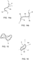
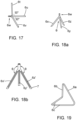
- one or more longitudinal rods may be provided through the housing for example, through the centre thereof or independently of the cylinder casing, forming shapes such as the ones providing the same rods orientations described in GB 2582123 A (such as the three or four edges tetrahedron, the lone circle linked to a perpendicular rod, the "Jack" shape or the snake), the contents of which are incorporated herein by reference; e.g. as shown in Figures 11 to 19 .
- one or more tranverse rods may be provided through the housing, extending in one or more planes which are substantially orthogonal to an axis of the housing, for example a longitudinal axis of a cylindrical housing.
- the markers according to the first aspect of the disclosure are provided in a helix shape or comprising multiple spaced apart rings, optionally including one or more straight longitudinal rods extending through the helix or rings.
- the marker is provided as a single helix combined with one longitudinal wire aligned parallel to a longitudinal axis of the helix, or as a multiple helix, e.g. a double, triple or quadruple helix.
- the pitch of the or each helical coil may be about 1.0-1.5 times the diameter of the coil.
- a detection system for locating an implantable marker comprising: an implantable marker according to the first aspect of the disclosure, at least one drive coil arranged to excite the marker with an alternating magnetic field and at least one sense coil arranged to detect a signal received from the excited marker; a magnetic field generator arranged to drive an alternating magnetic field through the at least drive coil; and at least one detector arranged to receive the signal from the sense coil and detect one or more harmonics of the drive frequency in the received signal.
- Magnetic flux density (B) is a vector quantity measuring the strength and direction of the magnetic field around a magnet or an electric current.
- Magnetic field strength also known as magnetizing field (H) is a vector field that describes the magnetic influence of an external magnetic field on moving electric charges, electric currents, and magnetic materials.
- Coercivity is the magnetizing field ( H ) needed to demagnetize a ferromagnetic material completely.
- Hard magnetic materials have a high coercivity. They are also referred as permanent magnets.
- Soft magnetic materials have low coercivity. They are easily magnetised and demagnetised.
- Magnetisation also known as magnetic polarisation (M) is a vector field that expresses the density of permanent or induced magnetic dipole moments in a magnetic material.
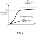
- Saturation of induction is the state reached when an increase in applied external magnetic field H cannot increase the magnetization M of the material further. In this state, the total magnetic flux density that results is called the saturation induction ( B s ), and the magnetisation is the saturation magnetisation ( M s ).
- Apparent initial susceptibility also known as effective susceptibility, is the initial susceptibility for a material of specific geometry in a small applied magnetic field. That is, it is ⁇ after taking into account the demagnetisation factor (see below).
- a ferromagnetic material has a variable relative permeability ( ⁇ r ) that increases relative to the magnetic field and up to a maximum. Many ferromagnetic materials have a maximum relative permeability that can exceed 100,000.
- a paramagnetic material has a constant relative magnetic permeability ( ⁇ r ) which is slightly more than 1.
- a diamagnetic material has a constant relative magnetic permeability ( ⁇ r ) slightly lesser than 1. Diamagnetism causes a repulsive effect by creating a small magnetic field in opposition to an externally applied field.
- Apparent relative magnetic permeability ( ⁇ app ) is the relative magnetic permeability of a material of specific geometry. That is, it is ⁇ r after taking into account the demagnetisation factor.
- Demagnetising field also known as stray field is the magnetic field ( H ) generated by the magnetisation ( M ). It gives rise to shape anisotropy in ferromagnets with a single magnetic domain, and to magnetic domains in larger ferromagnets.
- Demagnetisation factor is a number that describes the strength of the magnetic field produced by an object of specific geometry, compared to an object of infinite extent. It must be used in order to determine the demagnetising field.
- An arbitrarily shaped magnetic object has a total magnetic field that varies with location inside the object and can be quite difficult to calculate. This makes it very difficult to determine the magnetic properties of a material such as, for instance, how the magnetisation of a material varies with its shape and with the magnetic field.
- Magnetic anisotropy describes the variation of magnetic properties depending on the material orientation, relative to an externally applied magnetic field.
- the magnetic moment also known as magnetic dipole moment, is a vector quantity that describes the magnetic strength and orientation of a magnet or other object, such as an electric current loop, that produces a magnetic field H.
- MRI metal artefacts are distortions of the MR image characterised by a region of signal void (black) or bright fringing in the vicinity of a metal object. They occur at interfaces of tissues and metal with different magnetic susceptibilities, which cause local magnetic fields to distort the external magnetic field. This distortion changes the precession frequency in the tissue leading to spatial mis-mapping of information..
- the present disclosure relates to an improved magnetic marker that allows for surgical guidance and provides a small enough MRI artefact (preferably less than 2cm) so as to allow effective radio diagnostics. It has been surprisingly found that using thin wires of ferromagnetic material as defined herein, having a high length to diameter ratio (as defined above) of greater than 50, preferably at least about 500, more preferably at least 650, at least 750 or at least 1000, and low volume of less than about 1 ⁇ 10 -10 m 3 , a marker is created that provides a satisfactory sensing performance, balanced with a small MRI artefact.
- the markers of the present disclosure may be further improved by selecting ferromagnetic material with a low saturation induction which may further limit the MRI artefact size.
- the markers of the present disclosure may be further improved by selecting a ferromagnetic material with a high initial permeability which may improve sensing performance.
- Various shapes for such markers, which provide an improved isotropy of magnetic susceptibility have also been developed
- 'Artefacts' can be produced on an MRI image when an object changes the magnetic fields in an MRI machine.
- a marker of a ferromagnetic material will produce a significant artefact, reducing their appeal for use as a long-term marker for patients undergoing treatment such as neoadjuvant therapies prior to surgical excision.
- the artefact is predominantly generated by the component of the magnetic field generated by the ferromagnetic object ( B y ) that is in the same direction as the main field produced by the MRI machine (here referred to as the y -axis).
- B y is to shift the local Larmor frequency of protons near the object, and if that shift is large enough, those protons will not appear in the correct slice reconstructed by the MRI machine. That is, points at which
- the field produced by a ferromagnetic object can be described by the dipole model.
- B MRI B s V 2 ⁇ y 3 , where B marker,MRI is the field produced by the ferromagnetic material when in an MRI field.
- B B 0 + B marker,MRI . Therefore, it has been found that the strength of the magnetic field from the ferromagnetic object in an MRI machine is dependent on the volume of ferromagnetic material, its saturation induction and the distance away from it.
- m MV
- m ⁇ app HV
- markers comprising ferromagnetic material have been found to be unsuitable for purpose.
- a sphere cannot give the expected artefact size for the needed sense distance as the susceptibility will be low for any diameter. It has been found that for an MRI artefact with a diameter below 10mm under a 1.5T MRI field, the diameter of the sphere cannot exceed 0.18mm which would be too small to handle during manufacturing and to be seen by the surgeon after extraction of the tumour. On the other hand, to sense beyond 40mm, the sphere would need to exceed 1.1mm which would give an artefact much bigger that what would be considered acceptable.
- Example 1 Physical Properties of a Marker according to the disclosure.
- the microscopic dipoles produced in the object will interact constructively, thereby creating a stronger magnetic field, which in turn allows the marker to be detected more easily.
- Eddy currents induced in the material then create an additional magnetic field that partially shields the material from the external field, thus reducing the sense performance.
- Eddy currents can make a significant difference when the object subjected to the field has a large area perpendicular to the field.
- eddy currents actually do not significantly affect the sense performance of magnetic wires.
- eddy currents are significant if L / D > 1. Therefore, in order to reduce or remove the effect of eddy currents on the sense performance of a magnetic wire, it is preferably that the wire is thin.
- aspect ratio is the most important factor.
- initial relative permeability ( ⁇ r,i ) makes little difference as long as it is >1,000, as evident from Figure 1 .
- the magnitude of the ferromagnetic material's magnetic field induced under MRI determines the size of the MRI artefact.
- the range of B s for most ferro-magnetic materials is -0.25-1.5 T.
- the MRI field 1.5-3.0 T
- M s B s B s / ⁇ 0 . So, to minimize the artefact size, a material with a low B s is required.
- a minimal volume of magnetic material should be used, the aspect ratio should be high, and preferably the marker should have a high apparent initial susceptibility, and the material should have a low saturation induction, preferably less than about 1.0 T.
- Figure 3a is a simulation confirming the feasibility of a straight wire that is detectable at useful range while showing a small MRI artefact.
- the dot-dashed line shows, for each wire diameter, the maximum length permitted such that the MRI artefact of the wire has a diameter less than 10mm, assuming the wire material has a saturation induction B s of 1 T.
- the hatched region in the upper-left corner of the graph corresponds to the wire dimensions that simultaneously are detectable at 40mm or farther, and produce an MRI artefact of diameter 10mm or smaller. This figure shows that the wire length must be much greater than the wire diameter to satisfy both of these conditions simultaneously.
- Figure 3b shows the same simulated data as Figure 3a , but over a narrower range of wire diameters, and for more sense distances and saturation inductions.
- the dotted and dot-dashed lines have the same meaning as in Figure 3a .
- the dashed and solid lines correspond to additional values of sense distance and saturation induction as indicated in the legend. This figure shows that a wide range of wire dimensions can be used if one accepts a lower sense distance (30mm rather than 40mm); or if the material has a lower saturation induction (0.5T rather than 1T).
- a low saturation magnetization gives a small ferromagnetic dipole in the MRI scanner, and a high initial permeability means a small volume of material will give a large sense response on a probe such as magnetic susceptometry probes such as the one described in WO 2014/140566 A1 , the contents of which are incorporated herein by reference.
- the sense response under a magnetic susceptometry probe field and the MRI artefact of a ferromagnetic material depend on different variables. It has been recognised that in a small oscillating field, such as that produced by Sentimag TM , which is commercially available from Endomagnetics Ltd, UK, the sense performance depends almost exclusively on aspect ratio and volume, with a weaker dependence on the relative initial permeability, ⁇ r,i (the initial gradient of the B- ⁇ 0 H curve). In contrast, the magnitude of magnetic field produced by the marker in an MRI machine, and hence the MRI artefact size, depends on the saturation induction B s and volume of material.
- a marker having a large aspect ratio preferably having a length to diameter ratio of at least 50, more preferably at least 60, especially at least 100, and more especially at least about 500, with a low total volume, such as one having a length of at least 3mm, preferably being at least 6mm long with a diameter less than 100 ⁇ m, preferably having a diameter equal to or less than 50 ⁇ m, especially equal to or less than 30 ⁇ m piece of low-saturation-induction ferromagnetic material was found to be sensed adequately while producing a low MRI artefact.
- Example 2 Study into Preferred Materials for a Magnetic Marker according to the disclosure.
- Example 1 The marker described in Example 1 was further investigated to allow selection of the preferred magnetic materials that would produce the required high initial relative permeability ⁇ r,i > 1000, be formable into very thin strips or wire to allow the large aspect ratio but low volume to be configured, and having a low saturation induction B s ideally having a low B s of less than 1 T.
- Preferred materials that possess the required characteristics were found to be particular metals, amorphous metals and ceramic ferrites, preferably cobalt-based amorphous metals such as those sold under the trade names Yshield MCE61 TM , Metglas 2705M TM and Metglas 2714A TM ; Manganese-Zinc ceramic ferrites such as those sold under the trade names Fair-Rites 31 TM , 76 TM and 78 TM ; Nickel-iron-based soft ferromagnetic alloys such as those sold under the trade names Mu-metal, Permalloy 80, Permalloy C, Permalloy and Supermalloy; Nickel-Zinc ceramic ferrites such as those sold under the trade names Fair-Rites 15 TM , 20 TM , and 43 TM ; and more preferably Cobalt-based amorphous metals such as Yshield TM and Metglas 2714A TM .
- cobalt-based amorphous metals such as those sold
- Ceramics although having a low saturation induction, are less easy to form into wire or flat wire and therefore are less suitable for a marker according to the disclosure.
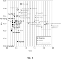
- Figure 4 is a plot of saturation induction against initial relative permeability for a wide variety of different materials.
- the materials which may form suitable markers are contained in the top left hand region of the graph, demonstrating low saturation induction and high relative initial permeability.
- Example 3 Investigation into Optimized Design for a Magnetic Marker according to the disclosure.
- the thin long wire marker discussed in relation to Examples 1 and 2 provides the required initial relative permeability ⁇ r,i > 1000, preferably > 10,000, large aspect ratio but low volume and has a low saturation induction B s .
- this type of marker has a high anisotropy ratio, demonstrating a strong sense response only in the direction of its axis.
- a marker may comprise a multitude of small ferromagnetic rods using the wire of Example 1 encapsulated within a single cylinder where all axes would be covered.
- this type of marker still faced several challenges in terms of detection sensibility (as short rods are expected to have a low axial susceptibility and some destructive interactive effects), MRI artefact (as the complexity of the magnetic dipoles would be at the utmost complexity to estimate), safety and regulation and manufacturing process for encapsulation of the rods and consistency.
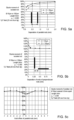
- Figure 5a shows that parallel rods placed 0.5mm apart from each other decrease the dipole moment by 5% for 50 ⁇ m diameter rods and by 10% for 100 ⁇ m diameter rods.
- Figure 5b two identical rods placed perpendicularly and where the ends are separated by a rod diameter length will increase the total dipole moment by 5%.
- perpendicular rods show a smaller decrease of their dipole moments if offset axially as seen in Figure 5c .
- marker configurations with closely spaced parallel rods were excluded as markers of the disclosure.
- satisfactory markers forming embodiments of the disclosure were configurations where it is possible to offset the placement of these parallel rods, as shown in Figure 5c .
- Further embodiments are shapes where perpendicular rods could be placed end on end.
- Preferred spacings for the rods are at least one diameter space apart.
- the rods provided in the required configuration may be encapsulated in a cylindrical housing as is known in the art.
- the marker may be packaged within other materials to ensure they are biocompatible to prevent a reaction with body tissue, and robust or a coating may be applied to the marker.
- the marker may be encased in a tube, for example made from Nitinol, titanium, stainless steel or other biocompatible alloys, the material preferably being non-magnetic and having a relatively low conductivity.
- Suitable coating materials include a polymer coating, such as FEP, Parylene, PTFE, ETFE, PE, PET, PVC or silicone or an epoxy based encapsulant.
- the quantity m z / V indicates how much sensing response the marker produces per unit volume.
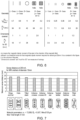
- Figure 7 of the accompanying drawings illustrates the configuration of a number of markers according to embodiments of the present disclosure that were found to produce the required low MRI artefact with good sense response in multiple directions.
- Figure 7 provides the sense distance at 200 mA for an artefact diameter of diameter 10mm.
- Example 4 Further Investigations in relation to helical coil marker according to examples of the present disclosure.
- a marker with a single helix design gets its transverse response from its helical coil, and the majority of its axial response from its axial rod, while a marker with the triple helix design uses a larger pitch to get both its transverse and axial response from its helical coil (the larger pitch means the coils point more towards the axial direction).
- pitch means the pitch of each constituent individual coil of the multiple helix, unless the clear context implies otherwise.
- the sense distance has been predicted using a combination of standard physics simulation software (COMSOL), custom computer models and experimentation, for one or several axial rods used and for two diameters, as shown in Table 2 below.
- Table 2 Length of axial rod (mm) ⁇ 15 ⁇ m Co-Fe amorphous metal predicted sense distance (mm) ⁇ 30 ⁇ m Co-Fe amorphous metal predicted sense distance (mm) 1 rod 2 rods 3 rods 4 rods 1 rod 2 rods 4 27 31 34 35 30 35 5 30 34 37 38 33 38 6 32 36 39 41 36 40 7 33 38 41 43 38 43 8 - - - - 40 - 9 - - - - 42 -
- Figure 8a and 8b show an optional housing or tube 80 in dotted lines located around the helical coil.
- the marker may be encased in a tube, for example made from Nitinol, titanium, stainless steel or other biocompatible alloys, the material preferably being non-magnetic and having a relatively low conductivity.
- Suitable coating materials include a polymer coating, such as FEP, Parylene, PTFE, ETFE, PE, PET, PVC or silicone or an epoxy based encapsulant.
- Table 3 shows that with the same total length of wire, the total number of turns per helix increases between one helix with a rod and a double helix or triple helix without rod.
- Table 3 Marker Size OD ⁇ L (mm) No. of helices Pitch (mm) Axial wire (mm) Turns per helix Total number of turns Total length of wire (mm) Length of marker (mm) 1.15 ⁇ 8.0 Single 1.0 8 8.0 8.0 38.0 8.0 1.15 ⁇ 8.0 Double 1.7 n/a 4.8 9.6 38.0 8.0 1.15 x 8.0 Triple 2.4 n/a 2.8 8.4 38.0 8.0
- the double helix and triple helix have higher pitch which was expected to give better axial detection but surprisingly and as shown in Table 4 below, the transverse detection was only slightly affected and even more surprisingly it has been found that the transverse detection increased.
- a major unexpected finding was also the non-destructive effect on the susceptibility of having helices interlaced in close proximity with one another, without touching.
- a single helix will present a short pitch and may require combination with a ferromagnetic rod.
- a double or triple helix incorporated into a marker with the same amount of material for the same length will require the helices to be stretched so that the pitch increases and this helps move the coils in a more axial direction but surprisingly does not decrease the transverse detection.
- a higher order helix may be used to provide more coils per unit length. However, if too many coils are closely packed together, (spacing less than 1 ⁇ the diameter of the coil), they will start to destructively interact.
- Marker size for all cases in Table 4 was diameter of 1.15mm and length of 8.0mm.
- Example 5 Investigation into alternative Ferromagnetic Materials for Markers according to the present disclosure.
- the markers hereinbefore disclosed all use thin wire as described in relation to Example 1 above to produce an optimized design of marker.
- preferred magnetic materials that would produce the required high initial relative permeability ⁇ r,i > 1000, preferably > 10,000, and have a low saturation induction B s may also be formable into strips, flat wires with an oblong section for providing markers according to the disclosure.
- Table 5 illustrates iron metal alloys having ⁇ r,i ⁇ 15,000 that meet the requirements for a marker according to the disclosure and may be provided in rolled sheet form prior to being cut into wires or strips.
- Table 5 Material (and type) Form B s (T) ⁇ r Curie temp (°C) Material size ( ⁇ m) Performance indicator** Co-Fe amorphous metal (Co-Fe amorphous metal) Wire 0.6 15,000 300 30 1 Metglas 2714A (Cobalt-based amorphous metal) Sheet 0.57 72,000 225 15 4.2 ULTRAPERM (Ni-Fe metal alloy) Sheet 0.74 300,000 360 20 1.8 Supermalloy (Ni-Fe metal alloy) Sheet 0.65 30,000 460 (20) (2.1) (**) Indicator of the amount of material available for a given artefact size. More material should give a stronger signal response.
- Marker designs can be created from these thin sheets using known manufacturing techniques, such as etching or laser cutting. These manufacturing techniques would aim to create wires that may or may not result in a flattened shape. In the case of flattened wire, the diameter described in other sections of this application essentially corresponds to the average radial length of the wire.
- the implantable markers according to the disclosure provide small ferromagnetic markers with good isotropy of magnetic susceptibility, sense distance and showing a small MRI artefact.
- Example 6 Use of Markers according to the disclosure in the monitoring and treatment of breast cancer.
- the markers according to the present disclosure are particularly suitable for the monitoring and treatment of breast cancer, enabling tracking of the size of the tumour during preliminary neoadjuvant therapy with the aim of shrinking the size of the tumourbelow 2cm long or to at least a size that is sufficiently small compared to the overall (BCS).
- Stage 2 breast cancer Patients that present a breast cancer tumour of more than 2cm but less than 5cm and which has not spread further than the lymphatic nodes in close proximity (often categorised as "Stage 2" breast cancer) can be offered BCS but this generally requires neoadjuvant therapy to shrink the tumour to around 2cm or less. In parallel with this, the healthcare professional will also need to assess the exact nature of the tumour, typically requiring a biopsy to be performed to sample some of the tumoral tissue.
- a marker according to the present disclosure can be placed in the cavity created by the tissue sampling in order to locate the tumour using a magnetic susceptometry probe, such as the probe described in WO 2014/140566 A1 . This enables the tumour to be located during future assessments of tumour progression and/or for ablation of the tumour.
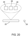
- a susceptometry detection system for locating a marker is shown in figure 20 , where a marker 20 according to the present disclosure is shown, along with a magnetic susceptibility probe 22, the probe 22 including a drive coil 24 arranged to excite the marker with an alternating magnetic field, and a detector 24 arranged to receive the signal from the sense coil.
- a magnetic field generator 28 is arranged to drive an alternating magnetic field through the drive coil 24, and the detector 24 is arranged to detect one or more harmonics of the drive frequency in the received signal.
- the marker of the disclosure also enables the tumour response to adjuvant therapy to be tracked by periodic examination, for example under MRI, due to the size of the artefact created under MRI field by the marker being kept to a minimum, ideally not more than 2cm long.
- the marker should not interfere with the assessment of tumour size while it is too big for BCS (essentially around 2cm but possibly more).
- the markers of the disclosure are particularly suitable for the protocol commonly pursued by healthcare professionals when tracking breast cancer progression under MRI due to their low induction saturation and low mass per volume which allows a significant reduction in the size of the MRI artefact.
- the healthcare professional is able to locate the tumour by means of the marker.
- the markers can be detected by a magnetic susceptometry probe that is positioned at least 3cm, up to 5cm, away thereby enabling a tumour which may be a few centimetres below the surface of the skin to be located. This enables the healthcare professional to determine the best path to access and remove the tumour by ablation prior to incision of the tissue.
- the marker 6 comprises a length of magnetic marker material bent to describe three or four edges 6a, 6b, 6c of a tetrahedron.
- the harmonic signal response of the marker is more uniform from any given direction of sensing.
- the radii of the bends 6d may be configured, e.g. by making them larger, to allow the marker to be packed into an outer tube more easily prior to deployment.
- the marker comprises a length of magnetic marker material bent into a portion of a circle 6e, with one end 6f bent radially towards the centre and then bent substantially at 90° out of the plane of the circle 6e to form a portion 6g along or parallel to the axis of the circle.
- the marker 6 comprises lengths of magnetic marker material arranged along three orthogonal axes x, y and z to form the shape of a 'jack' (also known as a jackstone or knucklebone).
- the marker comprises a length of magnetic marker material with a straight central section 6h and two further sections 6i, 6j, one at each end bent orthogonally from each other and from the central section.
- the radii of the bends 6k may be larger to allow the marker to be inserted into an outer tube more easily.
- the marker 6 comprises a length of magnetic marker material in the shape of a circular standing wave, i.e. formed into a uniform wave shape and then bent round to join the ends and form a circle in plan view.
- the marker comprises an elliptical or oval shaped length of magnetic marker material 6n with the wire ends 6o joined or close to one another but not joined.
- Two portions of the ellipse or oval at the ends of its longer axis are bent to approximately 90° of the plane of the ellipse.
- the bent portions comprise approximately one quarter to one third of the area of the ellipse or oval.
- the marker comprises three lengths of magnetic marker material 6t,6u,6v arranged orthogonally to each other to form substantially an orthogonal tripod or the vertex of a cuboid.
- the three lengths are joined with a joining section 6w that allows the lengths to he parallel to each other prior to deployment and then redeploy to form an orthogonal tripod.
- the marker comprises three lengths of magnetic marker material 6x,6y,6z arranged to form a tripod with a non-orthogonal angle between the legs of the tripod.
- the three lengths are joined with a joining section 6w that allows the lengths to be parallel to each other prior to deployment and then redeploy to form the tripod.
- the magnetic marker may comprise a wire made of ferromagnetic material in the form of a helical coil with the following properties: Criteria Magnetic marker Wire length 36 mm Wire diameter 0.015mm Total wire length to diameter ratio 2400 Volume of ferromagnetic material 6.4 ⁇ 10 -12 m 3 Total marker length excluding heat shrink and capsule 5 mm Pitch 1.6 mm Number of coils 3 coils Core diameter 1.2 mm Core length 5 mm Core volume 5.65x10 -9 m 3 Volume of diamagnetic/ferromagnetic 883
- the angle between the legs is chosen such that the harmonic magnetic response is as uniform as possible from any direction.
- the tripod is uniform with three equally spaced legs.
Landscapes
- Health & Medical Sciences (AREA)
- Life Sciences & Earth Sciences (AREA)
- Surgery (AREA)
- Engineering & Computer Science (AREA)
- Molecular Biology (AREA)
- Public Health (AREA)
- Veterinary Medicine (AREA)
- Biomedical Technology (AREA)
- Heart & Thoracic Surgery (AREA)
- Medical Informatics (AREA)
- Pathology (AREA)
- Animal Behavior & Ethology (AREA)
- General Health & Medical Sciences (AREA)
- Physics & Mathematics (AREA)
- Nuclear Medicine, Radiotherapy & Molecular Imaging (AREA)
- Oral & Maxillofacial Surgery (AREA)
- Human Computer Interaction (AREA)
- Biophysics (AREA)
- Condensed Matter Physics & Semiconductors (AREA)
- General Physics & Mathematics (AREA)
- Magnetic Resonance Imaging Apparatus (AREA)
- Media Introduction/Drainage Providing Device (AREA)
- Measurement Of Length, Angles, Or The Like Using Electric Or Magnetic Means (AREA)
Applications Claiming Priority (3)
| Application Number | Priority Date | Filing Date | Title |
|---|---|---|---|
| GB2115827.4A GB2612598B8 (en) | 2021-11-03 | 2021-11-03 | Magnetic markers for imaging and surgical guidance |
| EP22802690.2A EP4376761B1 (de) | 2021-11-03 | 2022-11-03 | Magnetische marker zur bildgebung und chirurgischen führung |
| PCT/GB2022/052779 WO2023079292A1 (en) | 2021-11-03 | 2022-11-03 | Magnetic markers for imaging and surgical guidance |
Related Parent Applications (1)
| Application Number | Title | Priority Date | Filing Date |
|---|---|---|---|
| EP22802690.2A Division EP4376761B1 (de) | 2021-11-03 | 2022-11-03 | Magnetische marker zur bildgebung und chirurgischen führung |
Publications (2)
| Publication Number | Publication Date |
|---|---|
| EP4462145A2 true EP4462145A2 (de) | 2024-11-13 |
| EP4462145A3 EP4462145A3 (de) | 2025-01-15 |
Family
ID=78828434
Family Applications (2)
| Application Number | Title | Priority Date | Filing Date |
|---|---|---|---|
| EP22802690.2A Active EP4376761B1 (de) | 2021-11-03 | 2022-11-03 | Magnetische marker zur bildgebung und chirurgischen führung |
| EP24203052.6A Pending EP4462145A3 (de) | 2021-11-03 | 2022-11-03 | Magnetische marker zur bildgebung und chirurgischen führung |
Family Applications Before (1)
| Application Number | Title | Priority Date | Filing Date |
|---|---|---|---|
| EP22802690.2A Active EP4376761B1 (de) | 2021-11-03 | 2022-11-03 | Magnetische marker zur bildgebung und chirurgischen führung |
Country Status (9)
| Country | Link |
|---|---|
| US (1) | US20250255693A1 (de) |
| EP (2) | EP4376761B1 (de) |
| JP (2) | JP7706648B2 (de) |
| CN (2) | CN118317744B (de) |
| AU (1) | AU2022382013B2 (de) |
| CA (1) | CA3234906A1 (de) |
| ES (1) | ES3002730T3 (de) |
| GB (1) | GB2612598B8 (de) |
| WO (1) | WO2023079292A1 (de) |
Families Citing this family (2)
| Publication number | Priority date | Publication date | Assignee | Title |
|---|---|---|---|---|
| GB2582123B (en) | 2018-01-25 | 2021-04-28 | Endomagnetics Ltd | Systems and methods for detecting magnetic markers for surgical guidance |
| US20260060776A1 (en) * | 2024-08-27 | 2026-03-05 | Izi Medical Products, Llc | Adaptive fudicials for multi-modal radiotherapy |
Citations (8)
| Publication number | Priority date | Publication date | Assignee | Title |
|---|---|---|---|---|
| US20040127787A1 (en) | 2002-12-30 | 2004-07-01 | Dimmer Steven C. | Implantable marker with a leadless signal transmitter compatible for use in magnetic resonance devices |
| WO2011067576A1 (en) | 2009-12-04 | 2011-06-09 | Endomagnetics Ltd. | Magnetic probe apparatus |
| WO2014013235A1 (en) | 2012-07-16 | 2014-01-23 | Endomagnetics Ltd | Magnetic marker for surgical localization |
| WO2014032235A1 (zh) | 2012-08-29 | 2014-03-06 | 华为技术有限公司 | 模块化天线装置及其配置方法 |
| WO2014140567A2 (en) | 2013-03-13 | 2014-09-18 | Endomagnetics Ltd. | Magnetic detector |
| WO2016193753A2 (en) | 2015-06-04 | 2016-12-08 | Endomagnetics Ltd. | Marker materials and forms for magnetic marker localization (mml) |
| EP3517068A1 (de) | 2018-01-25 | 2019-07-31 | Endomagnetics Ltd. | Systeme und verfahren zur detektion von magnetischen markern zur chirurgischen führung |
| US20210153970A1 (en) | 2018-03-23 | 2021-05-27 | Endomagnetics Limited | Magnetic markers for surgical guidance |
Family Cites Families (2)
| Publication number | Priority date | Publication date | Assignee | Title |
|---|---|---|---|---|
| US20060293581A1 (en) * | 2005-05-12 | 2006-12-28 | Sunnybrook And Women's College Health Sciences Centre | Marker device for X-ray, ultrasound and MR imaging |
| US12514676B2 (en) | 2019-07-10 | 2026-01-06 | Kyoto Prefectural Public University Corporation | Medical image guidance marker |
-
2021
- 2021-11-03 GB GB2115827.4A patent/GB2612598B8/en active Active
-
2022
- 2022-11-03 ES ES22802690T patent/ES3002730T3/es active Active
- 2022-11-03 CN CN202280073387.6A patent/CN118317744B/zh active Active
- 2022-11-03 AU AU2022382013A patent/AU2022382013B2/en active Active
- 2022-11-03 EP EP22802690.2A patent/EP4376761B1/de active Active
- 2022-11-03 EP EP24203052.6A patent/EP4462145A3/de active Pending
- 2022-11-03 CN CN202510603820.8A patent/CN120436807A/zh active Pending
- 2022-11-03 WO PCT/GB2022/052779 patent/WO2023079292A1/en not_active Ceased
- 2022-11-03 JP JP2024515046A patent/JP7706648B2/ja active Active
- 2022-11-03 US US18/706,356 patent/US20250255693A1/en active Pending
- 2022-11-03 CA CA3234906A patent/CA3234906A1/en active Pending
-
2025
- 2025-07-01 JP JP2025111266A patent/JP2025129273A/ja active Pending
Patent Citations (10)
| Publication number | Priority date | Publication date | Assignee | Title |
|---|---|---|---|---|
| US20040127787A1 (en) | 2002-12-30 | 2004-07-01 | Dimmer Steven C. | Implantable marker with a leadless signal transmitter compatible for use in magnetic resonance devices |
| WO2011067576A1 (en) | 2009-12-04 | 2011-06-09 | Endomagnetics Ltd. | Magnetic probe apparatus |
| WO2014013235A1 (en) | 2012-07-16 | 2014-01-23 | Endomagnetics Ltd | Magnetic marker for surgical localization |
| WO2014032235A1 (zh) | 2012-08-29 | 2014-03-06 | 华为技术有限公司 | 模块化天线装置及其配置方法 |
| WO2014140567A2 (en) | 2013-03-13 | 2014-09-18 | Endomagnetics Ltd. | Magnetic detector |
| WO2014140566A1 (en) | 2013-03-13 | 2014-09-18 | Endomagnetics Ltd. | Magnetic detector |
| WO2016193753A2 (en) | 2015-06-04 | 2016-12-08 | Endomagnetics Ltd. | Marker materials and forms for magnetic marker localization (mml) |
| EP3517068A1 (de) | 2018-01-25 | 2019-07-31 | Endomagnetics Ltd. | Systeme und verfahren zur detektion von magnetischen markern zur chirurgischen führung |
| GB2582123A (en) | 2018-01-25 | 2020-09-16 | Endomagnetics Ltd | Systems and methods for detecting magnetic markers for surgical guidance |
| US20210153970A1 (en) | 2018-03-23 | 2021-05-27 | Endomagnetics Limited | Magnetic markers for surgical guidance |
Non-Patent Citations (3)
| Title |
|---|
| HARGREAVES ET AL., METAL INDUCED ARTIFACTS IN MRI, August 2017 (2017-08-01) |
| KOH ET AL., INTRODUCTION OF A NEW STAGING SYSTEM OF BREAST CANCER FOR RADIOLOGISTS: AN EMPHASIS ON THE PROGNOSTIC STAGE, January 2019 (2019-01-01) |
| SHASHLA, NEOADJUVANT CHEMOTHERAPY IN BREAST CANCERS, September 2016 (2016-09-01) |
Also Published As
| Publication number | Publication date |
|---|---|
| EP4376761B1 (de) | 2024-10-23 |
| CN118317744A (zh) | 2024-07-09 |
| ES3002730T3 (en) | 2025-03-07 |
| CN120436807A (zh) | 2025-08-08 |
| GB202115827D0 (en) | 2021-12-15 |
| CA3234906A1 (en) | 2023-05-11 |
| WO2023079292A1 (en) | 2023-05-11 |
| EP4376761A1 (de) | 2024-06-05 |
| AU2022382013A1 (en) | 2024-05-02 |
| GB2612598B (en) | 2024-03-20 |
| CN118317744B (zh) | 2025-05-27 |
| AU2022382013B2 (en) | 2024-10-24 |
| EP4462145A3 (de) | 2025-01-15 |
| GB2612598B8 (en) | 2025-02-12 |
| JP2025129273A (ja) | 2025-09-04 |
| JP7706648B2 (ja) | 2025-07-11 |
| US20250255693A1 (en) | 2025-08-14 |
| JP2024537632A (ja) | 2024-10-16 |
| GB2612598A (en) | 2023-05-10 |
Similar Documents
| Publication | Publication Date | Title |
|---|---|---|
| KR102287648B1 (ko) | 수술 유도를 위한 자기 마커를 감지하는 시스템 및 방법 | |
| EP4326184B1 (de) | Verbesserungen an oder im zusammenhang mit implantierbaren ferromagnetischen markern | |
| US10595957B2 (en) | Marker materials and forms for magnetic marker localization (MML) | |
| EP4376761B1 (de) | Magnetische marker zur bildgebung und chirurgischen führung | |
| EP4426227B1 (de) | Verbesserungen an oder im zusammenhang mit implantierbaren ferromagnetischen markern | |
| CA3219444C (en) | Implantable ferromagnetic markers |
Legal Events
| Date | Code | Title | Description |
|---|---|---|---|
| PUAI | Public reference made under article 153(3) epc to a published international application that has entered the european phase |
Free format text: ORIGINAL CODE: 0009012 |
|
| STAA | Information on the status of an ep patent application or granted ep patent |
Free format text: STATUS: THE APPLICATION HAS BEEN PUBLISHED |
|
| AC | Divisional application: reference to earlier application |
Ref document number: 4376761 Country of ref document: EP Kind code of ref document: P |
|
| AK | Designated contracting states |
Kind code of ref document: A2 Designated state(s): AL AT BE BG CH CY CZ DE DK EE ES FI FR GB GR HR HU IE IS IT LI LT LU LV MC ME MK MT NL NO PL PT RO RS SE SI SK SM TR |
|
| RIN1 | Information on inventor provided before grant (corrected) |
Inventor name: VILLAR, GABRIEL Inventor name: UDALE, ROBINSON |
|
| REG | Reference to a national code |
Ref country code: DE Ref legal event code: R079 Free format text: PREVIOUS MAIN CLASS: G01R0033160000 Ipc: A61B0005060000 |
|
| PUAL | Search report despatched |
Free format text: ORIGINAL CODE: 0009013 |
|
| AK | Designated contracting states |
Kind code of ref document: A3 Designated state(s): AL AT BE BG CH CY CZ DE DK EE ES FI FR GB GR HR HU IE IS IT LI LT LU LV MC ME MK MT NL NO PL PT RO RS SE SI SK SM TR |
|
| RIC1 | Information provided on ipc code assigned before grant |
Ipc: A61B 17/00 20060101ALN20241210BHEP Ipc: G01R 33/16 20060101ALI20241210BHEP Ipc: A61B 90/00 20160101ALI20241210BHEP Ipc: A61B 5/06 20060101AFI20241210BHEP |
|
| STAA | Information on the status of an ep patent application or granted ep patent |
Free format text: STATUS: REQUEST FOR EXAMINATION WAS MADE |
|
| 17P | Request for examination filed |
Effective date: 20250708 |
|
| GRAP | Despatch of communication of intention to grant a patent |
Free format text: ORIGINAL CODE: EPIDOSNIGR1 |
|
| STAA | Information on the status of an ep patent application or granted ep patent |
Free format text: STATUS: GRANT OF PATENT IS INTENDED |
|
| INTG | Intention to grant announced |
Effective date: 20260210 |
|
| RIC1 | Information provided on ipc code assigned before grant |
Ipc: A61B 5/06 20060101AFI20260131BHEP Ipc: A61B 90/00 20160101ALI20260131BHEP Ipc: G01R 33/16 20060101ALI20260131BHEP Ipc: A61B 17/00 20060101ALN20260131BHEP |