EP4462811A1 - Applikationssystem mit passivem akustischem filter - Google Patents
Applikationssystem mit passivem akustischem filter Download PDFInfo
- Publication number
- EP4462811A1 EP4462811A1 EP23172785.0A EP23172785A EP4462811A1 EP 4462811 A1 EP4462811 A1 EP 4462811A1 EP 23172785 A EP23172785 A EP 23172785A EP 4462811 A1 EP4462811 A1 EP 4462811A1
- Authority
- EP
- European Patent Office
- Prior art keywords
- tube
- filter
- mems
- sound channel
- application system
- Prior art date
- Legal status (The legal status is an assumption and is not a legal conclusion. Google has not performed a legal analysis and makes no representation as to the accuracy of the status listed.)
- Withdrawn
Links
Images


Classifications
-
- H—ELECTRICITY
- H04—ELECTRIC COMMUNICATION TECHNIQUE
- H04R—LOUDSPEAKERS, MICROPHONES, GRAMOPHONE PICK-UPS OR LIKE ACOUSTIC ELECTROMECHANICAL TRANSDUCERS; ELECTRIC HEARING AIDS; PUBLIC ADDRESS SYSTEMS
- H04R1/00—Details of transducers, loudspeakers or microphones
- H04R1/20—Arrangements for obtaining desired frequency or directional characteristics
- H04R1/22—Arrangements for obtaining desired frequency or directional characteristics for obtaining desired frequency characteristic only
- H04R1/28—Transducer mountings or enclosures modified by provision of mechanical or acoustic impedances, e.g. resonator, damping means
- H04R1/2807—Enclosures comprising vibrating or resonating arrangements
- H04R1/2853—Enclosures comprising vibrating or resonating arrangements using an acoustic labyrinth or a transmission line
-
- H—ELECTRICITY
- H04—ELECTRIC COMMUNICATION TECHNIQUE
- H04R—LOUDSPEAKERS, MICROPHONES, GRAMOPHONE PICK-UPS OR LIKE ACOUSTIC ELECTROMECHANICAL TRANSDUCERS; ELECTRIC HEARING AIDS; PUBLIC ADDRESS SYSTEMS
- H04R1/00—Details of transducers, loudspeakers or microphones
- H04R1/20—Arrangements for obtaining desired frequency or directional characteristics
- H04R1/22—Arrangements for obtaining desired frequency or directional characteristics for obtaining desired frequency characteristic only
- H04R1/222—Arrangements for obtaining desired frequency or directional characteristics for obtaining desired frequency characteristic only for microphones
-
- H—ELECTRICITY
- H04—ELECTRIC COMMUNICATION TECHNIQUE
- H04R—LOUDSPEAKERS, MICROPHONES, GRAMOPHONE PICK-UPS OR LIKE ACOUSTIC ELECTROMECHANICAL TRANSDUCERS; ELECTRIC HEARING AIDS; PUBLIC ADDRESS SYSTEMS
- H04R1/00—Details of transducers, loudspeakers or microphones
- H04R1/20—Arrangements for obtaining desired frequency or directional characteristics
- H04R1/22—Arrangements for obtaining desired frequency or directional characteristics for obtaining desired frequency characteristic only
- H04R1/28—Transducer mountings or enclosures modified by provision of mechanical or acoustic impedances, e.g. resonator, damping means
- H04R1/2807—Enclosures comprising vibrating or resonating arrangements
- H04R1/2838—Enclosures comprising vibrating or resonating arrangements of the bandpass type
-
- H—ELECTRICITY
- H04—ELECTRIC COMMUNICATION TECHNIQUE
- H04R—LOUDSPEAKERS, MICROPHONES, GRAMOPHONE PICK-UPS OR LIKE ACOUSTIC ELECTROMECHANICAL TRANSDUCERS; ELECTRIC HEARING AIDS; PUBLIC ADDRESS SYSTEMS
- H04R19/00—Electrostatic transducers
- H04R19/04—Microphones
-
- H—ELECTRICITY
- H04—ELECTRIC COMMUNICATION TECHNIQUE
- H04R—LOUDSPEAKERS, MICROPHONES, GRAMOPHONE PICK-UPS OR LIKE ACOUSTIC ELECTROMECHANICAL TRANSDUCERS; ELECTRIC HEARING AIDS; PUBLIC ADDRESS SYSTEMS
- H04R2201/00—Details of transducers, loudspeakers or microphones covered by H04R1/00 but not provided for in any of its subgroups
- H04R2201/003—Mems transducers or their use
Definitions
- Embodiments of the present disclosure relate to an application system with a passive acoustic (attenuation or suppression) filter. More specifically, embodiments relate to the field of application systems comprising an application housing that houses a MEMS device (MEMS - micro electromechanical system) with a MEMS microphone or generally a MEMS sound transducer using passive acoustic filters for shaping the frequency response behavior of the MEMS microphone.
- MEMS device MEMS - micro electromechanical system
- MEMS microphone MEMS microphone
- MEMS sound transducer using passive acoustic filters for shaping the frequency response behavior of the MEMS microphone.
- MEMS sensor devices such as MEMS microphones.
- Examples of such application systems may include mobile phones, (e.g., noise cancelling) headphones or earphones, and hearing aids.
- Application systems with MEMS microphones have specific frequency response characteristics defined by their physical properties like MEMS attributes, such as for example their sound port and ventilation hole dimensions, back volume etc. In certain applications, there is a tradeoff between physical and acoustic properties.
- a small sound port in relation to the given package dimension could result in a low system resonance frequency, which can affect the sensitivity behavior over frequency as well as the noise within a desired audio bandwidth. Further, the system resonance can cause unwanted distortion and inter-modulation effects even if it is in the ultrasonic frequency range.
- a specified frequency response for standard microphones can extend to 100kHz (or even higher) nowadays.
- Such a range may include not only the aforementioned system resonance but also minor resonances such as standing-waves resonances in a back-cavity of the microphone or a membrane eigen resonance.
- Further microphone related issues may originate from intentional loud ultrasonic signals from sources like presence detectors, park-distance sensors, or invisible ultrasonic animals-fence speakers.
- electrical filter circuits can be implemented within the Mems device, the ASIC (Application-specific integrated circuit) or somewhere externally.
- ASIC Application-specific integrated circuit
- implementing electrical filter circuits can have different tradeoffs, having an influence on complexity, area, power, etc., and sometimes just touches the effect and not the root cause.
- a MEMS device e.g., a MEMS microphone
- an application system having improved operational characteristics, e.g., an improved frequency response and/or an improved adaptability of the frequency response for achieving an improved sensitivity behavior over frequency as well as of the noise behavior within an audio or ultrasonic bandwidth of the MEMS-based microphone of the application system.
- an application system comprises an application housing having a sound channel, a MEMS device arranged within the application housing, comprising: a MEMS package for providing an inner volume, a MEMS microphone arranged in the inner volume, and a MEMS sound port through the MEMS package to the inner volume, wherein the MEMS sound port is acoustically coupled to the sound channel of the application housing, and a passive acoustic filter enclosed in the application housing and acoustically coupled to the sound channel of the application housing.
- the passive acoustic filter (which may be a passive acoustic attenuation filter or passive acoustic suppression filter) may comprise a tube element or an extension cavity, which branches off from the sound channel.
- the tube element or extension cavity may have a tube length to provide an attenuation or suppression center frequency of the passive acoustic (attenuation) filter which corresponds to a frequency or frequency range of an acoustic resonance, e.g. of a Helmholtz resonance (peak) or a back-cavity resonance etc., in the inner volume of the MEMS package.
- the frequency range may be defined as a full width at half maximum (FWHM) of a sensitivity of the MEMS microphone.
- the attenuation center frequency may be a frequency in the center of the frequency range.
- the attenuation center frequency may define a frequency for which the tube element or extension cavity causes the most attenuation in the inner volume.
- the attenuation center frequency may be defined based on an arithmetic or geometric mean of a lower and upper cutoff frequency of the attenuation of the passive acoustic (attenuation) filter.
- the attenuation center frequency may correspond to a wavelength that is four times as long as an extension of the extension cavity (e.g., from its inlet to a closed end thereof).
- the passive acoustic (attenuation) filter may be formed as a passive acoustic notch filter acoustically coupled to the sound port, and wherein the tube element has a tube length to provide a notch center frequency of the passive acoustic notch filter which corresponds to a frequency or frequency range of a Helmholtz resonance (peak) or a back-cavity resonance in the inner volume of the MEMS package.
- the frequency range may be defined by a stopband of the notch filter.
- the notch center frequency may be a frequency in the center of the frequency range.
- the attenuation center frequency may define a frequency for which the passive acoustic notch filter causes the most attenuation in the inner volume.
- the notch center frequency may be defined based on an arithmetic or geometric mean of a lower and upper cutoff frequency of the attenuation of the passive acoustic notch filter.
- an undesired MEMS resonance behavior can be reduced by implementing the passive acoustic (attenuation) filter, which is coupled to the sound channel of the application system.
- a system level acoustic filter can shape the frequency response of the sound signal entering the application system.
- This passive acoustic (attenuation) filter can be understood as an additional degree of freedom in the system design of an application system, e.g., a mobile phone, headphones, ear phones, or hearing aids.
- the resonance of the application system can be influenced or set with the passive acoustic (attenuation) filter that may attenuate a resonance (peak) of the application system.
- brackets In the description of the embodiments, terms and text passages placed in brackets (next to a described element or function) are to be understood as further explanations, exemplary configurations, exemplary additions and/or exemplary alternatives of the described element or function.
- the term “lateral” means a direction parallel to the x- and/or y-direction, i.e. parallel to the x-y-plane, wherein the term “vertical” means a direction parallel to the z-direction.
- Fig. 1a shows an exemplary and general illustration of an application system 10 with a passive acoustic filter 16 (e.g., an attenuation filter) as a cross-sectional view (parallel to the x-z-axis), wherein the passive acoustic filter 16 comprises a tube extension 16-1, e.g. a tube element or an extension cavity 16-1, according to an embodiment.
- a passive acoustic filter 16 e.g., an attenuation filter
- the passive acoustic filter 16 comprises a tube extension 16-1, e.g. a tube element or an extension cavity 16-1, according to an embodiment.
- the application system 10 comprises an application housing 11 having a sound channel 13 and a MEMS device 15 arranged within the application housing 11.
- the MEMS device 15 comprises a MEMS package 21 (e.g., comprising or forming a MEMS housing) for providing an inner volume 24, a MEMS microphone (or generally a MEMS sound transducer) 12 arranged in the inner volume 24, a MEMS sound port 14 through the MEMS package 21 to the inner volume 24, wherein the MEMS sound 14 is acoustically coupled to the sound channel 13 of the application housing 11, and a passive acoustic filter 16 enclosed in the application housing 11 and acoustically coupled to the sound channel 13 of the application housing 11.
- the application system 10 may comprise an Application-specific integrated circuit (ASIC) 18.
- ASIC Application-specific integrated circuit
- the ASIC 18 may be configured to at least one of control the MEMS microphone 12, process signals received by the MEMS microphone, and provide and/or control power for the MEMS microphone 12.
- the sound channel 13 (or the volume of the sound channel 13) and the tube extension 16-1 of the passive acoustic (attenuation) filter 16 cooperate and/or interact for providing the acoustic filtering and/or attenuation effect, i.e. the passive acoustic (attenuation) filter functionality of the resulting passive acoustic (attenuation) filter 16.
- the dimensions of the sound channel 13 and of the tube extension 16-1 of the passive acoustic (attenuation) filter 16 may be adapted to each other for providing the acoustic filtering and/or attenuation effect, i.e. the passive acoustic (attenuation) filter functionality of the resulting filter arrangement 16.
- the MEMS housing 21 may have an interior (or inner) volume 24, wherein the MEMS housing 21 has the access opening or MEMS sound port 14 to the interior volume 24 of the application system 10 and the passive acoustic (attenuation) filter 16.
- the MEMS sound transducer 12 is arranged in the MEMS package 21 (e.g., in form of MEMS housing 21), for example, adjacent to the MEMS sound opening 14.
- the MEMS housing 21 may then comprise, for example, a substrate 20 and a MEMS lid structure 22 (e.g., a cap element 22), which may be at least partially electrically conductive.
- the substrate 20 may comprise or form a printed circuit board (PCB).
- PCB printed circuit board
- the MEMS device 15 may (or the MEMS housing 21) may comprise a PCB 25 (e.g., a flexible PCB).
- the substrate 20 may be arranged between (and optionally attached to) the PCB 25 and the MEMS lid structure 22.
- the MEMS sound transducer 12 (MEMS microphone) can subdivide the interior volume 24 into a front volume 24-1 and a back volume 24-2, wherein the front volume 24-1 is situated in the region between the MEMS sound port 14 and the MEMS microphone 12, and wherein the back volume 24-2 is situated on the opposite side of the MEMS sound transducer 12 with respect thereto in the interior volume 24 of the MEMS housing 21.
- the passive acoustic (attenuation) filter 16 having a tube extension 16-1 e.g. in form of a tube element or an extension cavity 16-1, are generally described together with the technical effects thereof.
- the passive acoustic (attenuation) filter 16 may comprise a tube element or an extension cavity 16-1 which branches off from the MEMS sound port 14.
- the tube element or extension cavity 16-1 may have a tube length "I" to provide an attenuation center frequency (e.g., a frequency that is attenuated the most by the acoustic filter 16) of the passive acoustic (attenuation) filter 16.
- the tube length "I" of the tube element or extension cavity 16-1 may be set to correspond or match to a frequency or frequency range of an acoustic resonance, e.g. of a Helmholtz resonance (peak) or a back-cavity resonance etc., in the inner volume 24 of the application system 10.
- the passive acoustic (attenuation) filter 16 is formed by a change of the cross-section of a length segment of the sound channel 13.
- the length segment of the sound channel 13 may comprise a widened or narrowed cross-section to form an acoustic low pass filter having a cut-off frequency below a frequency or frequency range of an acoustic resonance in the inner volume 24 of the MEMS package.
- the passive acoustic (attenuation) filter 16 may be formed as a passive acoustic "notch" filter acoustically coupled to the sound channel 13, wherein the tube element 16-1 has a tube length I to provide a notch center frequency of the passive acoustic notch filter 16 (e.g., a frequency that is attenuated the most by the acoustic filter 16).
- the notch center frequency of the passive acoustic notch filter 16 maybe set to correspond or match to a frequency or frequency range of an acoustic resonance, e.g. a Helmholtz resonance (peak) or a back-cavity resonance, in the inner volume 24 of the application system 10.
- the tube element 16-1 may have a comprise one or more straight or curved lumen section. At least one (straight of curved) lumen section may have cross-section in the shape of a circle, oval, rectangle, square, or polygon. At least one (straight or curved) lumen section may have a constant cross-section along a part or the entirety of its extension. At least one (straight or curved) lumen section may have a continuous or stepwise change in the shape of the cross section (e.g., in regard to size and contour). At least two (straight or curved) lumen sections may have connected by a bend, e.g., at an angle of at least essentially 45°, 60°, 90°, or 120.
- the sound channel 13 may any geometric property as discussed above with reference the tube element 16-1.
- the tube element (tube extension or extension cavity) 16-1 has a tube inlet 16a, which is acoustically coupled or connected to the sound channel 14.
- each tube element 16-1 of the plurality of tube elements 16-1 may have a tube inlet 16a, which is acoustically coupled or connected to the sound channel 13.
- the MEMS package 21 comprises the substrate structure 20 and the MEMS lid structure 22 (e.g., a cap element), wherein the MEMS sound port 14 extends through the substrate structure 20.
- the MEMS lid structure 22 e.g., a cap element
- the passive acoustic (attenuation) filter 16 may comprise a plurality of tube elements 16-1 which branch off from the sound channel 13. At least two tube elements 16-1 may be arranged to be oriented parallel or orthogonal relative to each other. See also Figs. 2a, b , 3a, 3b , 4a , and the associated description. It is noted that, unless specified in terms of a geometric orientation, the term "parallel" for a plurality of branches of tube elements 16-1 denotes branching off the common channel (e.g., sound channel 13) as opposed to an arrangement in series.
- the plurality of parallel tube elements 16-1 may have the same dimensions for providing the same attenuation center frequency (e.g., a frequency that is attenuated the most by the tube elements 16-1).
- an acoustic resonance e.g. of a Helmholtz resonance (peak) or a back-cavity resonance etc.
- a subset of the plurality of parallel tube elements 16-1 may have a different dimension "l1" with respect to the remaining tube elements 16-1 for providing a different attenuation center frequency (e.g., a frequency that is attenuated the most by the tube elements 16-1) with respect to the attenuation center frequency of the remaining tube elements 16-1.
- the tube element or extension cavity 16-1 may comprise the bypass tube, the tube inlet, and the tube outlet, wherein the tube inlet and the tube outlet acoustically couple the bypass tube to the sound channel 13.
- the tube element may further comprise a medium having a different speed of sound than a medium of the environmental atmosphere, wherein the bypass is filled with the medium.
- the tube element may further comprise aperture interfaces which seal the tube element 16-1 and provide an (effective) acoustic impedance coupling between the sound port 14channel 13 to the tube element 16-1. The aperture interfaces may prevent removal and/or evaporation of the medium.
- the application housing 11 comprises a substrate structure, wherein the sound channel 13 extends through the substrate structure, and wherein the passive acoustic (attenuation) filter 16 is part of the substrate structure.
- the tube element 16-1 may be integrated in the substrate structure, may be integrated in different layers of the substrate structure or may be part of a pre-molded module integrated to the substrate structure.
- the module integrated to the substrate may be preshaped by additive manufacturing (e.g., 3D printing) or subtractive manufacturing (e.g., milling and/or machining.
- the application housing comprises a substrate structure, wherein the sound channel 13 extends through the substrate structure, and wherein the passive acoustic (attenuation) filter 16 is part of the substrate structure (e.g., defined by a hollow lumen within the substrate structure).
- the tube element may be integrated in the substrate structure, may be integrated in different layers of the substrate structure or may be part of a pre-molded module integrated to the substrate structure.
- the MEMS package 21 comprises a MEMS substrate 20 structure and a MEMS lid structure 22, wherein the MEMS sound port 14 extends through the MEMS substrate structure 22 (and optionally through a PCB 25), and wherein the MEMS sound port 14 of the MEMS device 15 is directly coupled to the sound channel 13 of the application housing 21 (or indirectly via the PCB 25).
- the MEMS package 21 comprises a MEMS substrate structure 20 and a MEMS lid structure 22, wherein the MEMS sound port 14 extends through the MEMS lid structure 22, and wherein the MEMS sound port 14 of the MEMS device 15 is acoustically coupled (e.g., via an inner volume 24 of the application housing 21) to the sound channel 14.
- the passive acoustic (attenuation) filter 16 may be part of a pre-molded filter device module (e.g. an assembly part or component) attached to the application housing 21 at the sound channel 13, wherein the pre-molded filter module forms at least partially the sound channel 13.
- a pre-molded filter device module e.g. an assembly part or component
- the tube element 16-1 of the passive acoustic (attenuation) filter 16 may comprise a spiral tube 16-1 extending around the sound channel 13.
- the spiral tube 16-1 may comprise a varying or changing cross-section.
- the tube element 16-1 of the passive acoustic (attenuation) filter 16 may be filled with a medium or fluid 28 (e.g. a liquid, gas or gel) having a different speed of sound than the medium of the environmental atmosphere.
- a medium or fluid 28 e.g. a liquid, gas or gel
- the described concept of the passive acoustic (attenuation) filter 16 implements a package level acoustic filter into the microphones acoustic inlet (e.g., of the sound channel 13) design, wherein the passive acoustic (attenuation) filter 16 can shape the frequency response of the sound signal entering the MEMS package 21 of the application system 10 .
- the passive, acoustic filter element 16 can be understood as an additional degree of freedom in the system design of an application system comprising a MEMS microphone.
- the passive acoustic (attenuation) filter 16 can attenuate the application system's resonance peak (e.g., of a MEMS microphone of a phone, ear phone, or hearing aid) without adding noise in the band of interest.
- the application system 10 with the passive acoustic (attenuation) filter 16 can be implemented in or on the laminate (substrate structure) 20 or the lid (lid structure) 22 of the MEMS device 15 as extended variant of the standard acoustic inlet (MEMS sound port) 14.
- the passive acoustic (attenuation) filter 16 may be implemented directly with PCB manufacturing processes or by embedding/implementing dedicated acoustic filter elements 16 (filter assembly parts). These filter elements 16 may be manufactured with 3D printing, silicon-wafer, PCB, or other technologies.
- the passive acoustic (attenuation) filter 16 of the present disclosure can be implemented as a branch of the main acoustic inlet (sound channel) 13 in the application housing 11.
- a passive acoustic (attenuation) filter can be implemented as a passive acoustic notch filter.
- Passive acoustic (attenuation) filters in a parallel configuration can target different frequencies, such as e.g. back-cavity standing waves resonances at frequencies in the ultrasound band that are independent from the end application of the application system, in order to optimize the overall frequency response of the application system.
- a passive acoustic attenuation filter 16 does not introduce non-linear behavior or clipping and does not introduce additional noise, such as broadband noise, in the audio band.
- the sound channel 13 shown in Fig. 1a has a first length section 13-1 and a second length section 13-2, but may have any other number of length sections.
- the first and second length sections 13-1 have different lengths and are arranged perpendicular relative to each other.
- the second length section 13-2 is arranged perpendicular to the substrate structure 20.
- the tube extension 16-1 is oriented parallel to the substrate structure 20 and the first length section 13-1 and perpendicular to the second length section 13-2, which allows for a smaller height of the application system 10.
- the tube extension 16-1 and the first length section 13-1 may be arranged at least essentially in a same plane that is oriented parallel to the substrate structure 20.
- the tube extension 16-1 and the first length section 13-1 are arranged at least essentially co-axial.
- the tube extension 16-1 may form an extension of the first length section 13-1.
- Fig. 1b shows an exemplarily illustration of an application system 10, wherein the tube extension 16-1 and the first length section 13-1 are arranged in different parallel planes 34-1 and 34-2 that are separate from each other.
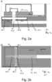
- Fig. 2a shows an exemplarily illustration of an application system 10 with a passive acoustic (attenuation) filter 16 having a plurality of parallel tube extensions 16-1 according to a further embodiment.
- Fig. 2a shows a bottom port configuration, wherein the MEMS sound port 14 extends through the substrate structure 20.
- the passive acoustic (attenuation) filter 16 may comprise a plurality of tube elements 16-1 which branch off from the sound channel 13.
- the plurality of parallel tube elements 16-1 may have the same dimensions for providing the same attenuation center frequency.
- an acoustic resonance e.g. of a Helmholtz resonance (peak) or a back-cavity resonance etc.
- a subset of the plurality of parallel tube elements 16-1 may have a different dimension "l1" with respect to the remaining tube elements 16-1 for providing a different attenuation center frequency with respect to the attenuation center frequency of the remaining tube elements 16-1.
- an acoustic resonance e.g. of a Helmholtz resonance (peak) or a back-cavity resonance etc.
- an acoustic resonance e.g. of a Helmholtz resonance (peak) or a back-cavity resonance etc.
- All the parallel configurations with the plurality of tube elements or tube extensions 16-1 can eventually be extended to arrays of acoustic filters 16 and can target one single frequency (to be attenuated), or also subsets of the branches 16-1 or each single branch can be targeting a different frequency (to be attenuated) in order to optimize the overall frequency response of the system 10. That applies for example to back-cavity standing waves resonances in the inner volume 24 that usually happen at a well-defined frequency in the ultrasound band and that is pretty much independent from the end-application of the MEMS microphone 12.
- Each tube element 16-1 of the plurality of tube elements 16-1 has a tube inlet 16a, which is acoustically coupled or connected to the sound channel 13.
- Fig. 2b shows a schematic top view of an exemplary application system 10, wherein the passive acoustic (attenuation) filter 16 comprises a plurality of tube elements 16-1 which branch off from the sound channel 13.
- the tube elements 16-1 branch off the second length section 13-2.
- at least one or all tube elements 16-1 may branch off the first length section 13-1.
- At least two (or all) tube elements 16-1 may extend in a common plane.
- At least two tube elements 16-1 may be arranged orthogonal relative to each other.
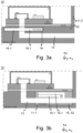
- Fig. 3a shows a schematic side view of an exemplary application system 10 with a plurality of tube elements 16-1.
- the application housing 11 comprises an outer housing 11-2 and a pre-molded filter module 52, wherein the outer housing 11-2 is configured to receive the pre-molded filter module 52.
- the outer housing 11-2 and the pre-molded filter module 52 are not limited to the example shown in Fig. 3a and may be implemented in any other embodiment described herein. Different pre-molded filter modules 52 may be combined with different outer housings 11-2 (e.g., in order to allow for different configurations of the sound channel 13), which increase design flexibility of the application system 10.
- the pre-molded filter module 52 shown in Fig. 3a has two tube elements 16-1.
- the application system 10 may have a pre-molded filter module 52 with a different number (e.g., three, four, five, six, or more) and/or different types (e.g., a Herschel-Quincke tube or an extension cavity) of tube elements 16-1.
- Different types of pre-molded filter modules 52 may be used in order to realize different filtering characteristics (e.g., degree of filtering, filtering of a selected frequency of frequency spectrum). As a result, the filtering characteristics can be easily adapted by selecting a specific pre-molded filter module 52, without having to change the entire application housing 11.
- the pre-molded filter module 52 may define a routing of the sound channel 13 (e.g., a straight sound channel or a sound channel that bends towards different directions). Therefore, the pre-molded filter module 52 can be used to adapt the sound channel 13 to the outer housing 11-2 and/or the MEMS device 15. For example, an outer housing 11-2 for a hearing aid may require a different routing of the sound channel 13 than an outer housing 11-2 of a mobile phone. The required routing of the sound channel 13 may be realized by a corresponding selection of the pre-molded filter module 52.
- Fig. 3b shows a schematic side view of a further exemplary application system 10 with a plurality of tube elements 16-1.
- the passive acoustic attenuation filter 16 is exemplarily implemented as a dedicated filter element (e.g. as an assembly part or component) 16 in form of a pre-formed filter module 52 that is inserted into and fixed to a cavity or recess 11-1 of the application housing 11, wherein the pre-molded filter module 52 comprises two tube elements 16-1 acoustically coupled to the sound channel 13.
- the depicted tube elements 16-1 of the passive acoustic attenuation filter 16 are exemplarily implemented as a ⁇ /4 tube extensions. Therefore, the tube elements 16-1 shown in Fig. 3b each have an inlet from the sound channel 13 at one end and is closed at the other end.
- At least one of the tube elements 16-1 may comprise a bend (e.g., a 90° bent). Such a bend may allow for a more compact arrangement of the application system 10 (e.g., by orienting a portion of one or more tube elements 16-1 parallel to the substrate structure 20).
- the application housing 11 comprises an outer housing 11-2 and an pre-molded filter module 52 having the cavity 11-1, wherein the outer housing 11-2 is configured to receive the pre-molded filter module 52.
- the outer housing 11-2 and the pre-molded filter module 52 are not limited to the example shown in Fig. 3b and may be implemented in any other embodiment described herein. Different pre-molded filter module 52 may be combined with different outer housings 11-2 (e.g., in order to allow for different configurations of the sound channel), which increase design flexibility of the application system 10.
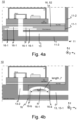
- Fig. 4a shows a schematic side view of a further exemplary application system 10 with a plurality of tube elements 16-1.
- Fig. 4a shows an exemplarily illustration of an application system 10 with the passive acoustic attenuation filter 16 according to a further embodiment.
- the passive acoustic attenuation filter 16 is exemplarily implemented as a dedicated filter element in form of a pre-molded filter module 52 (e.g. as an assembly part or component) that is inserted into and fixed to a cavity or recess 11-1 of the application housing 11, wherein the pre-molded filter module 52 comprises four tube elements 16-1 acoustically coupled to the sound channel 13.
- any other number of tube elements 16-1 e.g., one, two, three, five, six, or more
- any other number of tube elements 16-1 may be implemented instead.
- the depicted tube elements 16-1 of the passive acoustic attenuation filter 16 are exemplarily implemented as a ⁇ /4 tube extension. Therefore, the tube elements 16-1 shown in Fig. 4a have each an inlet from the sound channel 13 at one end and is closed at the other end.
- the application housing 11 may further comprise a pre-molded module 11-3, which may form a portion of the sound channel 13.
- the cavity 11-1 may be configured to receive the pre-molded module 11-3.
- the pre-molded module 11-3 may form an adapter between the pre-molded filter module 52 and the outer housing 11-1.
- the pre-molded module 11-3 may increase design flexibility (e.g., of the sound channel 13) and increase manufacturing efficiency (e.g., by requiring less precise manufacturing parameters).
- Fig. 4b shows an exemplary application system 10 with a passive acoustic (attenuation) filter 16 where the tube element 16-1 is exemplarily implemented as a Herschel-Quincke tube.
- Fig. 4b shows a bottom port configuration, where the MEMS sound port 14 extends through the substrate structure 20.
- the tube element or extension cavity 16-1 of the passive acoustic (attenuation) filter 16 may be implemented as a bypass tube or bypass cavity having a bypass inlet 16-a and a bypass outlet 16-b, which are acoustically coupled to the sound channel 13.
- the bypass inlet 16a is arranged in the sound channel 13 acoustically upstream to the bypass outlet 16b (or further away from the sound port 14 than the bypass outlet 16b).
- upstream in the MEMS sound port 14 relates to the sound traveling direction into the MEMS package 21 to the MEMS device 12.
- the tube element 16-1 of the passive acoustic attenuation filter 16 may be filled with a medium or fluid 28 (e.g. a liquid, gas or gel) having a different speed of sound than the medium of the environmental atmosphere.
- a medium or fluid 28 e.g. a liquid, gas or gel
- the tube element or extension cavity 16-1 of the passive acoustic attenuation filter 16 may be implemented as a Herschel-Quincke tube, which comprises a parallel branch 16-1 to a main acoustic path 13. Its purpose is to create an acoustic attenuation filter, e.g. an acoustic notch filter, in order to acoustically attenuate defined frequency components of an acoustic signal traveling through the acoustic system, i.e. through the sound channel 13 and into the MEMS package 21.
- an acoustic attenuation filter e.g. an acoustic notch filter
- the length I of the parallel branch 16-1 may have dimensions in the range of 3 mm to 9 mm.
- a sound port 14 may, for example, have a radius r of 575 ⁇ m and a length l SP of 200 ⁇ m with an HQ-tube 16-1 of equal cross section as the main inlet 13.
- an attenuation of the resonance peak may be in the range of 8 dB, depending on the specific dimensions of the sound port 14 and the tube element 16-1.
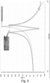
- Fig. 5 shows an example of Helmholtz resonance attenuation of a typical microphone inlet (575 ⁇ m radius 200 ⁇ m length) with an Herschel-Quincke tube 16-1 of equal cross section as the main inlet 13 according to an embodiment.
- the optimization brings to a Herschel-Quincke tube of 4.15mm ( ⁇ 42kHz resonance) and an attenuation of the resonance peak of 8dB.
- Fig. 5 takes into account a possible (simple and inexpensive) way of producing the cavities/tubes 16-1.
- the stacking of an additional PCB finalizes the final application housing 11 for of a PCB stack.
- middle layers e.g. dielectric layers
- the passive acoustic (attenuation) filter 16 can be implemented system PCB comprised by the application system 11.
- the passive acoustic (attenuation) filter 16 can be implemented e.g. into or as part of the outer housing, mold component or similar as extended variant of the standard acoustic system inlet.
- the passive acoustic (attenuation) filter 16 may be formed by processes that may include one or more of injection molding, additive manufacturing (e.g., 3D printing), and subtractive manufacturing (e.g., milling and/or machining).
- the passive acoustic filter 16 and/or the application housing 11 may be manufactured with system manufacturing/assembly processes or by embedding/implementing one or more dedicated pre-molded filter modules (e.g., acoustic filter elements).
- a dedicated pre-molded filter module may be manufactured with 3D printing, formed in a silicon-wafer, formed in a PCB, or formed by molding or other technologies.
- the sound channel 13, in which the pre-molded filter module is inserted may in addition include other elements like mashes, membranes, or a sealing.
- the geometric constraints (length "I” and cross-sectional area) for the HQ tube element 16-1 can be relaxed, for example, allowing the radius of the HQ tube element 16-1 to be different than the one of the main inlet (sound port) 14.
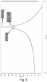
- Fig. 6 exemplarily shows the attenuation in an application system 10 with the passive acoustic (attenuation) filter 16 having the tube element 16-1 in form of a Herschel-Quincke tube.
- the tube element 16-1 may be tuned to attenuate the desired frequency or frequency range, comparable to a notch filter, but implemented as a passive element.
- the passive acoustic attenuation filter 16 may be, when implemented as a Herschel-Quincke tube 16-1, adapted to attenuate a specific frequency or a frequency band by changing the length of the parallel branch 16-1.
- the Herschel-Quincke tube may be adapted by changing the portion of the main acoustic path that is shunted by the parallel branch. The longer the shunted portion of the main acoustic path, the better is the attenuation.
- the Herschel-Quincke t8aube has a radius that is less than half the radius of the sound port, here 225 ⁇ m and 575 ⁇ m, respectively. The attenuation notch becomes wider in bandwidth. An attenuation may be more effective and flat.
- Embodiments of the present concept for providing the application system 10 with the passive acoustic attenuation filter 16 allows to realize an attenuation of the requested frequency, frequencies or frequency ranges without an noise impact in the audio band.
- PSD power spectrum density
- the passive acoustic attenuation filter 16 having the tube element 16-1 in form of a Herschel-Quincke tube it can be seen how there is a broadening of the resonance peak with no effect in the audio band. This (critical) feature cannot be achieved with traditional techniques which reduce the Q factor of the resonance and show a significant impact on the noise at all frequencies.
- An additional optimization parameter is the portion (length l SP ) of the main inlet 13 that is shunted by the HQ-tube element 16-1.
- An optimization can show that the longer the shunted part l SP the better, but already the equipartitioned case (1/3 of the full inlet 14) shows good results.
- Fig. 7 exemplarily shows the attenuation in an application system 10 with the passive acoustic attenuation filter 16 having the tube element 16-1 in form of a Herschel-Quincke tube 16-1 in the equipartitioned case (1/3 of the full inlet 14).
- Fig. 8a shows an exemplarily illustration of an application system 10 with the passive acoustic attenuation filter 16 according to a further embodiment.
- the passive acoustic attenuation filter 16 is exemplarily implemented as a dedicated filter element (e.g. as an assembly part or component) 16 in form of a pre-molded filter module 52 that is inserted into and fixed to a cavity or recess 11-1 of the application housing 11, wherein the tube element 16-1 is configured as a spiral (or helix) around the sound channel 13.
- the depicted tube element 16-1 of the passive acoustic attenuation filter 16 is exemplarily implemented as a ⁇ /4 tube extension. Therefore, the tube element 16-1 shown in Fig. 8a has an inlet from the sound channel 13 at one end and is closed at the other end.
- the application housing 11 further comprises an outer housing 11-2 and an pre-molded module 11-3 with the cavity 11-1, wherein the outer housing 11-2 is configured to receive the pre-molded module 11-3.
- the outer housing 11-2 and the pre-molded module 11-3 are not limited to the example shown in Fig. 8a and may be implemented in any other embodiment described herein.
- the cavity 11-1 may be formed in at least one of the pre-molded module 11-3 and the outer housing 11-2. Different pre-molded module 11-3 may be combined with different outer housings 11-2 (e.g., in order to allow for different configurations of the sound channel), which increase design flexibility of the application system 10.
- the dedicated element (filter device) 16 may comprise the sound channel 13 or at least a portion of the sound channel 13 and the tube element 16-1 of the passive acoustic (attenuation) filter 16.
- the tube element 16-1 of the passive acoustic attenuation filter 16 may comprise a spiral tube 16-1 extending around the sound channel 13.
- the spiral tube 16-1 may comprise a varying or changing cross-section.
- the spiral tube 16-1 may have a rectangular, square, circular, oval, polygonal cross-section, or a combination of any of these cross-sections.
- the cross-section may change in at least one of shape and size.
- the spiral tube 16-1 may extend at least one, two, or three times around the sound channel 13.
- Fig. 8b shows an application system 10 with the passive acoustic (attenuation) filter 16 exemplarily implemented as Herschel-Quincke tube 16-1, such as a parallel branch 16-1, implemented as a dedicated element 16 (filter device) in form of a pre-molded module that is implemented into a cavity 11-1 in the application housing 11.
- the passive acoustic (attenuation) filter 16 exemplarily implemented as Herschel-Quincke tube 16-1, such as a parallel branch 16-1, implemented as a dedicated element 16 (filter device) in form of a pre-molded module that is implemented into a cavity 11-1 in the application housing 11.
- the passive acoustic (attenuation) filter 16 with the tube element 16-1 may be implemented as a dedicated filter element (filter device) 16 in form of a pre-molded filter module 52 that is implemented into the cavity 11-1 in the application housing 11.
- the dedicated element 16 may comprise the sound channel 13 or at least a portion of the sound channel 13 and the tube element 16-1 of the passive acoustic (attenuation) filter 16.
- the dedicated element (filter device) 16 may be arranged in the cavity or recess 11-1 in the application housing 11, such that the tube element 16-1 of the dedicated element (filter device) 16 branches off from the sound channel 13 and is acoustically coupled to the sound channel 13.
- Fig. 9a shows an application system 10 with a passive acoustic (attenuation) filter 16 with a Herschel-Quincke tube and a parallel branch 16-1 as the tube element 16-1.
- the passive acoustic attenuation filter 16 is implemented as a dedicated element (filter device) 16 in form of a pre-molded filter module 52 that is implemented into the cavity or recess 11-1 in an application housing 11, wherein the parallel branch 16-1 is designed as a spiral (or helix) around the main inlet (sound channel) 13.
- a tube element 16-1 such as a Herschel-Quincke tube, comprises a tube inlet 16a and a tube outlet 16b, which are acoustically coupled to the sound channel 13 wherein the tube inlet 16a is arranged in the sound channel 13 acoustically upstream to the tube outlet 16b.
- the Herschel-Quincke tube 16-1 may be implemented as a spiral, e.g. helical element, around the sound channel 13 with the tube inlet 16a and the tube outlet 16b acoustically coupled to the sound channel 13.
- the tube element 16-1 may be attached as a dedicated filter device 16, e.g., in form of a pre-molded filter module 52, e.g. as a dedicated assembly part or component, to the application housing 11, e.g. to the cavity or recess 11-1 of the application housing 11.
- the passive acoustic (attenuation) filter 16 may be part of the dedicated filter device 16 (e.g., a pre-molded filter module 52) mechanically fixed or attached to the MEMS package 21 at the sound port 14, wherein the filter device 16 comprises (at least partially) the sound channel 13 and the tube element 16-1.
- the dedicated filter device 16 may be mechanically fixed or attached to the outer housing 11-2 (e.g., as shown in Fig. 8a ). Further alternatively, the dedicated filter device 16 (e.g., a pre-molded filter module 52) may be arranged spatially separate from the MEMS package 21 and the outer housing 11-2.
- Fig. 9b shows a schematic view comprising the passive acoustic attenuation filter 16 according to a further embodiment.
- the application housing 11 may comprise one or more layers of a laminate 17a, b, c, d, e, e.g.
- the laminate 17 may form or be part of a substrate structure 50. planes (or any other number of layers such as n layers with n ⁇ 3, 5, 7, etc.).
- the passive acoustic attenuation filter 16 may be implemented in the layers 17a-e of the laminate 17.
- the application housing 11 may comprise metallization layers (e.g., laminate layers 17b and 17d), which are separated by and/or embedded in an insulation (dielectric) material of the application housing 11 (e.g., laminate layers 17a, c, e). At least a part of the entire laminate 17 may comprise layers 17a-e, wherein material of the respective layer alternates between metal and insulating material.
- metallization layers e.g., laminate layers 17b and 17d
- an insulation (dielectric) material of the application housing 11 e.g., laminate layers 17a, c, e.
- At least a part of the entire laminate 17 may comprise layers 17a-e, wherein material of the respective layer alternates between metal and insulating material.
- the application housing 11 may be adapted to comprise the tube element 16-1 by structuring at least one (or a plurality) of the layers 17a-e of the laminate 17.
- the application housing 11 may be adapted to comprise the tube extension 16-1, e.g. a ⁇ /4 tube extension 16-1 within at least one of the layers 17a-e of the laminate 17 that forms (or is part of) the application housing 11.
- There may be one or more tube elements 16-1 formed within at least a portion of a layer or layers 17a-e of laminate of an application housing 11.
- Fig. 9b shows one tube elements 16-1.
- the passive acoustic attenuation filter 16 can be implemented in the laminate (substrate structure) 17 of the application system 10 as extended variant of the standard acoustic inlet (sound channel) 13.
- the tube element 16-1 may also be realized by only two layers, wherein each layer forms at least part of the tube element 16-1.
- one layer may form a recess that forms the volume of the tube element 16-1 and a portion of the sound channel 13 (e.g., such a combination of layers 17a and b as shown in Fig. 9b ) and the other layer may form an inner surface of the tube element 16-1 and the rest of sound channel (e.g., such as a combination of layers 17c-e as shown in Fig. 9b ).
- a Herschel-Quincke tube 16-1 may be formed in two layers, wherein a portion of the Herschel-Quincke tube 16-1 is formed in each layer.
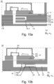
- Fig. 10a shows an application system 10 with a passive acoustic attenuation filter 16 where the tube element 16-1 is implemented as a Herschel-Quincke tube 16-1 in the layers of a laminate 17 configured as (at least part of) the application housing 11.
- the laminate 17 may comprise one or more layers 17.
- the laminate 17 may form or be part of a substrate structure 50.
- the application housing 11 may be adapted to comprise the tube element 16-1 by structuring a plurality of the layers 17-n of the laminate 17.
- the substrate structure 20 may be adapted to comprise the tube extension 16-1, e.g. a Herschel-Quincke tube 16-1, within the layers 17-n of the laminate 20 that forms the substrate structure 20.
- Fig. 10a shows one tube elements 16-1.
- the passive acoustic attenuation filter 16 can be implemented in the laminate (which may form or be part of the application housing) 17 of the application system 10 as extended variant of the standard acoustic inlet (sound channel) 13.
- the tube element(s) 16-1 of the passive acoustic attenuation filter 16 may be implemented directly with PCB manufacturing processes, additive manufacturing, subtractive manufacturing, or by embedding (implementing) dedicated acoustic filter elements 16-1.
- Fig. 10b shows a schematic view comprising the passive acoustic attenuation filter 16 according to a further embodiment.
- the passive acoustic attenuation filter 16 is formed by a change of the cross-section 19 of a length segment 23 of the sound channel 13.
- the cross-section 19 of the sound channel 13 may have generally a round shape, an oval shape, a rectangular shape, a square shape, or a polygonal shape.
- the change of the cross-section 19 of the length segment 23 may include a change in at least one of the shape and the size.
- the change of the cross-section 19 may comprise a constant first cross section 19b along the length segment 23 that is different than a second cross section 19a of the sound channel beyond the length segment 23.
- the length segment 23 of the sound channel 13 may comprise a widened or narrowed cross-section 19b to form an acoustic low pass filter having a cut-off frequency below a frequency or frequency range of an acoustic resonance in the inner volume 24 of the MEMS package 21.
- the widened or narrowed cross-section 19b may larger by 5%, 10%, 25%, 50%, 100%, or 200% or smaller by 5%, 10%, 25%, 50%, 75%, or 90% (e.g., compared to the cross-section 19a of the sound channel 13 upstream and/or downstream of the length segment 23).
- 10b shows an example of a length segment 23 of the sound channel 13 with a narrowed cross-section 19b to form an acoustic low pass filter having a cut-off frequency below a frequency or frequency range of an acoustic resonance in the inner volume 24 of the MEMS package 21.
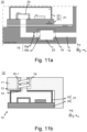
- Fig. 11a shows a schematic view comprising the passive acoustic (attenuation) filter 16 according to a further embodiment, wherein a length segment 23 of a sound channel 13 comprises a widened cross-section 19b.
- Fig. 11b shows a schematic view of an application system 10 with the passive acoustic (attenuation) filter 16.
- the application system 10 is implemented in a top port microphone configuration with a sound channel 13 and a passive acoustic (attenuation) filter (e.g. filter device) 16 stacked on a lid structure 22.
- a passive acoustic (attenuation) filter e.g. filter device
- the MEMS package 21 comprises a MEMS substrate structure 20 and a MEMS lid structure 22, wherein the MEMS sound port 14 extends through the MEMS lid structure 22, and wherein the MEMS sound port 14 of the MEMS device 12 is acoustically coupled to the sound channel 13.
- the MEMS lid structure 22 may be connected (e.g., abutment or attachment) with the application housing 11 directly (e.g., as shown in Fig. 11b ) or indirectly (e.g., using intermittent layers).
- the MEMS substrate structure 20 may be attached to the application housing 11.
- the passive acoustic (attenuation) filter 16 that comprises a tube element 16-1 that is configured as a spiral (or helix) around the main inlet (sound channel 13).
- any other form of passive acoustic filter 16 may be implemented as well.
- the sound port 14 may extend through the lid structure 22 and be acoustically coupled to the sound channel 13.
- the application housing 11 that comprises that passive acoustic attenuation filter 16 may be fixed to the lid structure 22.
- the passive acoustic attenuation filter 16 may be integrated in different layers of the application housing 11 and/or may be attached (e.g. as an assembly part or component) to the lid structure 22.
- the passive acoustic attenuation filter 16 may be a dedicated element (filter device) 16 (e.g., in form of a pre-molded module 16) attached to the lid structure 22
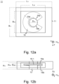
- Fig. 12a-b shows a schematic illustration of an application housing 11 with a passive acoustic attenuation filter 16 having a tube element 16-1 in form of a Herschel-Quincke tube element exemplarily in two corresponding schematic views.
- the plan view of Fig. 12a exemplarily depicts a length L 11 of (at least a portion such as a substrate of) the application housing 11, a length L 16 of a filter device 16 (such as a pre-molded module 16) comprising at least partially the sound channel 13 with a diameter D 13 and the passive acoustic attenuation filter 16 with the tube element 16-1 in form of a Herschel-Quincke tube with a tube width TW.
- Fig. 12a further depicts a width B 11 of the application housing 11 and a width B 16 of the passive acoustic attenuation filter 16 or the filter device 16 with the passive acoustic attenuation filter 16, respectively.
- the filter device 16 with the passive acoustic attenuation filter 16 may be located within the application housing 11, wherein the sound channel 13 may be aligned with the MEMS microphone 12 within the MEMS device 15.
- the height H 11 is the height or thickness of the application housing 11
- the height H 16 is the height or thickness of the filter device 16
- the height H 16-1 is the height or diameter of the tube element 16-1 within the filter device 16.
- the tube element 16-1 may have a square, rectangular, circular, ellipsoid cross-section or any other form or combination of forms.
- the dimension D 14 indicates the diameter of the sound channel 13.
- the tube element 16-1 of the passive acoustic attenuation filter 16 may comprise a spiral tube 16-1 extending around the sound channel 13.
- the spiral tube 16-1 may comprise a varying or changing cross-section.
- the tube element or extension cavity 16-1 of the passive acoustic attenuation filter 16 may implemented as a bypass tube or bypass cavity having a bypass inlet 16a and a bypass outlet 16b, which are acoustically coupled to the sound channel 13.
- the passive acoustic attenuation filter 16 may, for example, have a sound port diameter D 14 of 1.15 mm.
- the tube element 16-1 may be implemented as a Herschel-Quincke tube and may for example have a width TW of the tube of 0.8mm.
- the tube of the Herschel-Quincke tube element 16-1 may have a rectangular cross-section.
- H 11 may for example be 0.45 mm
- H 16 may be 0.27 mm
- H 16-1 may be 0.20 mm.
- TW may for example be 0.8 mm.
- the dimensions may vary with respect to the desired wavelength to be canceled or attenuated and/or the available space within the application system 10.
- the implemented dimensions of the MEMS device can vary at least in a range of +/-50 %, +/- 30 % or +/- 10 % of the indicated dimensions (the upper limit for the range may vary further such as +100%, 200% or 500%).
- the passive acoustic attenuation filter 16 may be attached to the MEMS housing 21 and/or inserted into a recess 11-1 and may comprise at least partially the sound channel 13 and the annular tube element 16-1 which is provided around the sound channel 13 in order to form the tube element 16-1 of the passive acoustic attenuation filter 16 acoustically coupled to the sound channel 13.
- the filter channel (tube element) 16-1 in between should be made as large as possible in order to provide a low acoustic resistance.
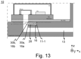
- Fig. 13 shows a schematic illustration of an application system 10 with the passive acoustic attenuation filter 16 having the tube element 16-1 in form of a Herschel-Quincke tube (a bypass branch) that may be filled with a medium or fluid 28, e.g., a liquid, gas or gel, that has a different speed of sound compared to the medium of the environmental atmosphere.
- a medium or fluid 28 e.g., a liquid, gas or gel
- the passive acoustic attenuation filter 16 having the tube element 16-1 may be implemented as a dedicated filter element (e.g. as an assembly part or component) 16 (e.g., in form of a pre-molded module 16) that is implemented into a cavity or recess 11-1 of the application housing 11 (e.g., an outer housing 11-2 and/or an pre-molded module 11-3 thereof).
- a dedicated filter element e.g. as an assembly part or component
- a pre-molded module 16 e.g., in form of a pre-molded module 16
- the application system 10 of Fig. 13 may be implemented in correspondence to the application system 10 of Fig. 4b with a passive acoustic attenuation filter 16 having the tube element 16-1.
- Fig. 13 shows a first aperture interface 30a covering and fluidically closing the tube inlet 16a and a second aperture interface 30b covering and fluidically closing the tube outlet 16b of the tube element 16.
- the first and second aperture interfaces 30a, 30b provide and maintain an acoustical coupling of the sound channel 13 to the tube element 16-1, which may be filled with the medium 28.
- the acoustical coupling of the sound channel 13 to the tube element 16-1 may be achieved by means of aperture interfaces 30a, 30b which seal the tube element 16-1 and provide an (effective) acoustic impedance coupling between the sound channel 13 to the tube element 16-1.
- the medium 28 in the tube element (filter branches) 16-1 may for example be Helium, Hydrogen, Perfluorobutane (PFB) or Sulfur Hexafluoride or the like.
- PFB Perfluorobutane
- Sulfur Hexafluoride or the like.
- a size of the passive acoustic attenuation filter 16 may be made smaller than without the medium 16 within the tube element 16-1.
- a filter frequency may be downshifted, for example by keeping or by changing the dimensions of the tube element 16-1.
- the result would be to either shrink the physical dimensions of the acoustic filter 16, or to downshift the filter frequency by keeping the dimension of the acoustic filter 16.
- the filter branch length "I" scales directly with the speed of sound
- Fig. 14 shows a concept representation of one exemplary implementation option and the simulation results for the different considered cases.
- high speed of sound media 28 results in very compact filters 16 but slightly less effective, while low speed of sound media 28 allows the direct scaling of the branch 16-1 with the speed of sound ratio with respect to air (PFB speed of sound ⁇ 4 times lower than air so the filters are ⁇ 4 times shorter) while maintaining the excellent filtering performance.
- Fig. 15 shows three exemplary results for an application system 10 with the passive acoustic (attenuation) filter 16 implemented as a ⁇ /4 tube element 16-1.
- Fig. 15 shows the effect of different tubes radii from 90 ⁇ m to 125 ⁇ m to 220 ⁇ m.
- Fig. 15 shows the basic performance for the embodiments, and especially the importance of maximizing the radius of the branch 16-1 so to reduce the resistance and allow for larger portion of the flow to pass through the by-pass 16-1.
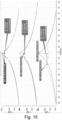
- Fig. 16 shows three exemplary results for an application system 10 with the passive acoustic (attenuation) filter 16 implemented as a ⁇ /4 tube element 16-1.
- the results were obtained using four parallel tube elements 16-1 of the same length (for the specific example of 2mm) and different tube radii for each of the resulting graphs, respectively (here, 90, 125 and 215 ⁇ m).
- ⁇ /4 tube elements 16-1 need approximately twice as much tubes 16-1 in parallel with respect to Herschel-Quincke tubes 16-1.
- Implementing ⁇ /4 tube elements 16-1 may be less complex than implementing Herschel-Quincke tubes 16-1.
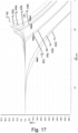
- Fig. 17 shows results of simulations of a low pass passive acoustic filter 16.
- a passive acoustic filter 16 may be formed by a change of the cross-section 19 of a length segment 23 of the sound channel 13 (e.g., as depicted in Figs. 10b and 11a ).
- a low pass acoustic filter 16 may be realized by modification of parameters other than the cross-section 19. More specifically, the results shown in Fig. 17 relate to a narrowed cross-section as, for example, shown in Fig. 10b .
- Line 40 indicates a frequency response of a reference application system (without a passive acoustic filter 16) with resonance frequency of 18kHz.
- the reference system may for example be a hearing aid.
- Lines 42a-d, 44a-d indicate a frequency response of application system with a passive acoustic filter, wherein the dashed lines 42a-d indicate a length of a length segment 23 of 150 ⁇ m and the continuous lines 44a-d indicate a length of a length segment 23 of 240 ⁇ m.
- the four lines 42a-d and the four lines 44a-d respectively indicate a radius of a cross-section 19b of 25 ⁇ m, 50 ⁇ m, 100 ⁇ m, and 150 ⁇ m. It is noted that these values (as well as any exemplary values disclosed herein) are mere examples. Alternatively, a range of ⁇ 5%, ⁇ 10%, 30%, 50% around these values or a range between any of these values may be used instead.
- the frequency response is decreased by the passive acoustic filter, wherein an attenuation of the frequency response is increased with smaller radius of the cross-section 19b of the length segment 23.
- a larger degree of narrowing results in a larger degree of attenuation.
- the attenuation is more pronounced for the longer length segment (see lines 44a-d) than for the shorter length segment (see lines 42a-d).
- the size (e.g., the radius) of the cross-section of the length segment 23 may be used (e.g., primarily) to set a cut-off frequency.
- Fig. 18 shows results of simulations of noise of the low pass passive acoustic filter 16 simulated in Fig. 17 .
- the noise increases with a larger cross-section (e.g., radius) of the length segment 23 and decreases with a smaller cross-section (e.g., radius) of the length segment 23. If the cut-off happens in the audio range (as exemplarily shown in Fig. 18 ), the integrated noise in the audio band may remain fairly constant.
- Similar simulations have been performed for a length segment 23 with a narrowed cross-section and a length of 3mm.
- the simulations for different diameters of the narrowed cross-section resulted in a system signal-to-noise ratio (SNR) of 67.5 dBA for a diameter of 200 ⁇ m, of 66.5dBA for a diameter of 400 ⁇ m, of 66.5dBA for a diameter of 600 ⁇ m, and of 66.5dBA for a diameter of 800 ⁇ m. Therefore, the SNR stays mostly constant over the tested diameters, while system resonances may be attenuated to a desired level or essentially cancelled out.
- SNR system signal-to-noise ratio
- the passive acoustic (attenuation) filter 16 can be adapted for easily for specific requirements of the application system. For example, different types of application systems may require different frequencies to be filtered and/attenuated. For example, a microphone for a mobile phone may require filtering different frequencies or frequency ranges than a hearing aid.
- the passive acoustic (attenuation) filter 16 may be adapted in the application housing 11, requiring less or no modification of the MEMS device 15. As a result, the same or similar microphones can be implemented in different application systems 10 (that may have different and better adjusted passive acoustic (attenuation) filters 16).
- the passive acoustic (attenuation) filter 16 may have improved performance. Better performance may be the result of passive acoustic (attenuation) filter 16 being arranged closer to a beginning of the signal processing chain of the application system 10. Furthermore, passive acoustic (attenuation) filter 16 can make use of the size of the application housing 11. For example, a large application housing 11 may allow for a passive acoustic (attenuation) filter 16 with at least one of a larger number of tube elements 16-1, larger tube elements 16-1, and different types of tube elements 16-1.
- the passive acoustic (attenuation) filter 16 may be easier and more effectively implemented in the application system 10.
- the formation of structures of the filter 16 e.g. of the tube elements 16-1) can be separated from the manufacturing process of the MEMS device 15. Therefore, the manufacturing process of the application system 10 is more effective.
- the passive acoustic filter 16 may provide additional degree of freedom in the application system design incorporating a MEMS microphone.
- the filter element 16-1 may be able to attenuate, for example, the a resonance peak of the application system (including the MEMS microphone) while adding less (or no) noise in the frequency band of interest.
- Another example of an application may be the use as an acoustic low pass filter, attenuating out of audio-band signals.
- the passive acoustic filter can be implemented in various parts of the application housing 11, e.g., into the outer housing 11-2, a PCB of the application system, or a pre-molded module as extended variant of the standard acoustic system inlet.
- the passive acoustic (attenuation) filter 16 can beneficially influence system Helmholtz resonance behavior without additional power consumption of the application system of otherwise necessary electronic filter circuits.
- the system Helmholtz resonance behavior can be controlled by the passive acoustic (attenuation) filter 16, even if there are external physical requirements for the MEMS package and/or the application system.
- attention on the detailed ultrasound behavior of the audio system may be achieved with the passive acoustic (attenuation) filter 16.
- the passive acoustic (attenuation) filter 16 may help to prevent ASIC internal nonlinear behavior/clipping of even physical nonlinear behavior/clipping of the MEMS component without additional power consumption.
- the passive acoustic (attenuation) filter 16 allows to shape the frequency response behavior of the MEMS microphone very early, i.e. at the beginning of the signal processing chain of the application system 10.
- Acoustic resonances e.g. Helmholtz resonances
- the acoustic filter element 16 is inserted at the application system level in order to attenuate one or more resonance peaks (early in the system).
- the passive acoustic (attenuation) filter 16 is acoustically coupled to the sound channel 13 of the application system or is arranged adjacent to it and is designed as ⁇ /4 branches 16-1 or an HQ tube (Herschel-Quincke tube) 16-1.
- HQ tube Herschel-Quincke tube
- Several acoustic filter elements 16-1 can also be combined, on the one hand to increase the filter efficiency for a certain resonance frequency and/or to attenuate several resonance frequencies (resonance states).
- the passive acoustic (attenuation) filter 16 may be inserted as an additional (independent) component in a section of the application housing 11, e.g. in a recess 11-1 provided for this purpose, and is glued (mechanically connected) to the application housing 11 and optionally the MEMS package 21, for example.
- the passive acoustic (attenuation) filter 16 allows to shape the frequency response of the microphone package 21, e.g. in a frequency range from 0 to 100 kHz, i.e., if possible, receive no resonances (standing acoustic waves) within the housing to avoid possible interference or negative influences on the MEMS component and/or the ASIC.
- the application system comprises an application housing having a sound channel, a MEMS device arranged within the application housing, comprising a MEMS package for providing an inner volume, a MEMS microphone arranged in the inner volume, and a MEMS sound port through the MEMS package to the inner volume, wherein the MEMS sound port is acoustically coupled to the sound channel of the application housing, and a passive acoustic filter enclosed in the application housing and acoustically coupled to the sound channel of the application housing.
- the passive acoustic filter is formed by a change of the cross-section of a length segment of the sound channel.
- the length segment of the sound channel comprises a widened or narrowed cross-section to form an acoustic low pass filter having a cut-off frequency below a frequency or frequency range of an acoustic resonance in the inner volume of the MEMS package.
- the passive acoustic filter comprises a tube element or an extension cavity, which branches off from the sound channel.
- the tube element has a tube length to provide an attenuation center frequency of the passive acoustic filter which corresponds to a frequency or frequency range of an acoustic resonance in the inner volume of the MEMS package.
- the passive acoustic filter is a passive acoustic notch filter acoustically coupled to the sound channel, and wherein the tube element has a tube length to provide a notch center frequency of the passive acoustic notch filter which corresponds to a frequency or frequency range of a Helmholtz resonance or a back-cavity resonance in the inner volume of the MEMS package.
- the tube element comprises a bypass tube having a tube inlet and a tube outlet, which are acoustically coupled to the sound channel, wherein the tube inlet is arranged in the sound channel acoustically before the tube outlet.
- the tube element comprises a ⁇ /4 tube extension having a tube inlet, which is acoustically coupled to the sound channel.
- the passive acoustic filter comprises a plurality of tube elements which branch off from the sound channel.
- the plurality of parallel tube elements have the same dimensions for providing the same attenuation center frequency.
- a subset of the plurality of parallel tube elements has a different dimension with respect to the remaining tube elements for providing a different attenuation center frequency with respect to the attenuation center frequency of the remaining tube elements.
- the application housing comprises a substrate structure, wherein the sound channel extends through the substrate structure, and wherein the passive acoustic filter is part of the substrate structure.
- the tube element is integrated in the substrate structure, is integrated in different layers of the substrate structure or is part of a pre-molded module integrated to the substrate structure.
- the MEMS package comprises a MEMS substrate structure and a MEMS lid structure, wherein the MEMS sound port extends through the MEMS substrate structure, and wherein the MEMS sound port of the MEMS device is directly coupled to the sound channel of the application housing.
- the MEMS package comprises a MEMS substrate structure and a MEMS lid structure, wherein the MEMS sound port extends through the MEMS lid structure, and wherein the MEMS sound port of the MEMS device is acoustically coupled to the sound channel.
- the passive acoustic filter is part of a pre-molded filter module attached to the application housing at the sound channel, wherein the pre-molded filter module forms at least partially the sound channel.
- the tube element of the passive acoustic filter comprises a spiral tube extending around the sound channel.
- the tube element of the passive acoustic filter is filled with a medium having a different speed of sound than the medium of the environmental atmosphere.
- embodiments of the control circuitry can be implemented in hardware or in software or at least partially in hardware or at least partially in software.
- embodiments of the control circuitry can be implemented as a computer program product with a program code, the program code being operative for performing one of the methods when the computer program product runs on a computer.
- the program code may, for example, be stored on a machine readable carrier.
Landscapes
- Health & Medical Sciences (AREA)
- Otolaryngology (AREA)
- Physics & Mathematics (AREA)
- Engineering & Computer Science (AREA)
- Acoustics & Sound (AREA)
- Signal Processing (AREA)
- Soundproofing, Sound Blocking, And Sound Damping (AREA)
Priority Applications (1)
| Application Number | Priority Date | Filing Date | Title |
|---|---|---|---|
| EP23172785.0A EP4462811A1 (de) | 2023-05-11 | 2023-05-11 | Applikationssystem mit passivem akustischem filter |
Applications Claiming Priority (1)
| Application Number | Priority Date | Filing Date | Title |
|---|---|---|---|
| EP23172785.0A EP4462811A1 (de) | 2023-05-11 | 2023-05-11 | Applikationssystem mit passivem akustischem filter |
Publications (1)
| Publication Number | Publication Date |
|---|---|
| EP4462811A1 true EP4462811A1 (de) | 2024-11-13 |
Family
ID=86332239
Family Applications (1)
| Application Number | Title | Priority Date | Filing Date |
|---|---|---|---|
| EP23172785.0A Withdrawn EP4462811A1 (de) | 2023-05-11 | 2023-05-11 | Applikationssystem mit passivem akustischem filter |
Country Status (1)
| Country | Link |
|---|---|
| EP (1) | EP4462811A1 (de) |
Citations (3)
| Publication number | Priority date | Publication date | Assignee | Title |
|---|---|---|---|---|
| US20180317025A1 (en) * | 2017-03-02 | 2018-11-01 | Sonion Nederland B.V. | A sensor comprising two parallel acoustical filter elements, an assembly comprising a sensor and the filter, a hearable and a method |
| US20220369025A1 (en) * | 2021-05-11 | 2022-11-17 | Infineon Technologies Ag | Mems microphone and package with integrated passive acoustic filter, extended soundport |
| US20230045906A1 (en) * | 2021-08-11 | 2023-02-16 | Shenzhen Shokz Co., Ltd. | Microphones |
-
2023
- 2023-05-11 EP EP23172785.0A patent/EP4462811A1/de not_active Withdrawn
Patent Citations (3)
| Publication number | Priority date | Publication date | Assignee | Title |
|---|---|---|---|---|
| US20180317025A1 (en) * | 2017-03-02 | 2018-11-01 | Sonion Nederland B.V. | A sensor comprising two parallel acoustical filter elements, an assembly comprising a sensor and the filter, a hearable and a method |
| US20220369025A1 (en) * | 2021-05-11 | 2022-11-17 | Infineon Technologies Ag | Mems microphone and package with integrated passive acoustic filter, extended soundport |
| US20230045906A1 (en) * | 2021-08-11 | 2023-02-16 | Shenzhen Shokz Co., Ltd. | Microphones |
Similar Documents
| Publication | Publication Date | Title |
|---|---|---|
| EP4090049B1 (de) | Mems-vorrichtung mit einem passiven akustischen dämpfungsfilter | |
| EP3282443B1 (de) | Mems-mikrofonanordnung | |
| US11968487B2 (en) | Adapters for microphones and combinations thereof | |
| US11653143B2 (en) | Helmholtz-resonator for microphone assembly | |
| US20050207605A1 (en) | Microphone and method of producing a microphone | |
| KR101514363B1 (ko) | 소형 라우드 스피커 모듈, 상기 모듈의 주파수 응답을 개선시키기 위한 방법 및 전자 장치 | |
| US20070223735A1 (en) | Electroacoustic Transducer System and Manufacturing Method Thereof | |
| JP2009044600A (ja) | マイクロホン装置およびその製造方法 | |
| US9906855B2 (en) | Reducing ported transducer array enclosure noise | |
| CN114531632A (zh) | 通气声换能器及相关方法和系统 | |
| EP3398352B1 (de) | Treibergehäuse mit öffnung und akustischen widerstandselementen | |
| CN113938788A (zh) | 音频输出装置与电子设备 | |
| EP4462811A1 (de) | Applikationssystem mit passivem akustischem filter | |
| US11917348B2 (en) | Covering structure, sound producing package and related manufacturing method | |
| EP2786592B1 (de) | Elektroakustischer wandler zur montage auf einem substrat | |
| EP1542496B1 (de) | Lautsprechergehäuse mit einer Schallöffnung zur Kompensation des Einflusses der akustischen Moden auf den Frequenzgang | |
| US20230370767A1 (en) | Sound-receiving system, and electronic device | |
| JP7721582B2 (ja) | スピーカモジュール | |
| CN224154356U (zh) | 封装和系统 | |
| JP2010057052A (ja) | マイクロホンユニット | |
| CN117041809A (zh) | 一种电子设备 |
Legal Events
| Date | Code | Title | Description |
|---|---|---|---|
| PUAI | Public reference made under article 153(3) epc to a published international application that has entered the european phase |
Free format text: ORIGINAL CODE: 0009012 |
|
| STAA | Information on the status of an ep patent application or granted ep patent |
Free format text: STATUS: THE APPLICATION HAS BEEN PUBLISHED |
|
| AK | Designated contracting states |
Kind code of ref document: A1 Designated state(s): AL AT BE BG CH CY CZ DE DK EE ES FI FR GB GR HR HU IE IS IT LI LT LU LV MC ME MK MT NL NO PL PT RO RS SE SI SK SM TR |
|
| STAA | Information on the status of an ep patent application or granted ep patent |
Free format text: STATUS: THE APPLICATION IS DEEMED TO BE WITHDRAWN |
|
| 18D | Application deemed to be withdrawn |
Effective date: 20250514 |