EP4462935A1 - Verfahren und vorrichtung zur datenkomprimierung - Google Patents
Verfahren und vorrichtung zur datenkomprimierung Download PDFInfo
- Publication number
- EP4462935A1 EP4462935A1 EP22917796.9A EP22917796A EP4462935A1 EP 4462935 A1 EP4462935 A1 EP 4462935A1 EP 22917796 A EP22917796 A EP 22917796A EP 4462935 A1 EP4462935 A1 EP 4462935A1
- Authority
- EP
- European Patent Office
- Prior art keywords
- data compression
- cell
- terminal device
- configuration
- sdt
- Prior art date
- Legal status (The legal status is an assumption and is not a legal conclusion. Google has not performed a legal analysis and makes no representation as to the accuracy of the status listed.)
- Pending
Links
Images

Classifications
-
- H—ELECTRICITY
- H04—ELECTRIC COMMUNICATION TECHNIQUE
- H04W—WIRELESS COMMUNICATION NETWORKS
- H04W28/00—Network traffic management; Network resource management
- H04W28/02—Traffic management, e.g. flow control or congestion control
- H04W28/06—Optimizing the usage of the radio link, e.g. header compression, information sizing, discarding information
-
- H—ELECTRICITY
- H04—ELECTRIC COMMUNICATION TECHNIQUE
- H04L—TRANSMISSION OF DIGITAL INFORMATION, e.g. TELEGRAPHIC COMMUNICATION
- H04L69/00—Network arrangements, protocols or services independent of the application payload and not provided for in the other groups of this subclass
- H04L69/04—Protocols for data compression, e.g. ROHC
-
- H—ELECTRICITY
- H03—ELECTRONIC CIRCUITRY
- H03M—CODING; DECODING; CODE CONVERSION IN GENERAL
- H03M7/00—Conversion of a code where information is represented by a given sequence or number of digits to a code where the same, similar or subset of information is represented by a different sequence or number of digits
- H03M7/30—Compression; Expansion; Suppression of unnecessary data, e.g. redundancy reduction
- H03M7/60—General implementation details not specific to a particular type of compression
- H03M7/6011—Encoder aspects
-
- H—ELECTRICITY
- H04—ELECTRIC COMMUNICATION TECHNIQUE
- H04W—WIRELESS COMMUNICATION NETWORKS
- H04W4/00—Services specially adapted for wireless communication networks; Facilities therefor
- H04W4/02—Services making use of location information
-
- H—ELECTRICITY
- H04—ELECTRIC COMMUNICATION TECHNIQUE
- H04W—WIRELESS COMMUNICATION NETWORKS
- H04W72/00—Local resource management
- H04W72/04—Wireless resource allocation
- H04W72/115—Grant-free or autonomous transmission
Definitions
- the present invention or disclosure relates to the technical field of communications, and more particularly, to a method and an apparatus for data compression.
- SDT small data transmission
- the packet header compression function for packets in 5G systems includes robust header compression (ROHC) and Ethernet header compression (EHC).
- ROHC robust header compression
- EHC Ethernet header compression
- Embodiments of the present invention provide a method and an apparatus for data compression so that a terminal device may perform data compression in a target data compression area while performing an SDT, thus improving a performance of data transmission.
- a method for data compression performed by a terminal device, including: receiving small data transmission (SDT) configuration information from a network side device, the SDT configuration information being used for instructing a terminal device to perform an SDT; determining a target data compression area; in response to the terminal device being located in the target data compression area, executing the data compression while performing the SDT.
- SDT small data transmission
- the terminal device may receive the SDT configuration information from the network side device, the SDT configuration information being used for instructing the terminal device to perform the SDT, may determine a target data compression area, and in response to the terminal device being located in the target data compression area, may execute the data compression while performs the SDT. In this way, the terminal device may perform the data compression in the target data compression area while performing the SDT, thus improving the performance of data transmission.
- another method of data compression is provided, performed by a network side device, including: sending, to the terminal device, SDT configuration information used for instructing a terminal device to perform an SDT; sending the data compression configuration to the terminal device; wherein the data compression configuration comprises a data compression area configuration.
- a communication apparatus which has a function of realizing some or all of the functions of the terminal device in the method described in the first aspect.
- the functions of the communication apparatus may have the functions in some or all embodiments in the present invention, or may have the functions which implement any one of the embodiments in the present invention alone.
- the functions may be realized by hardware or by hardware executing corresponding software.
- the hardware or software includes one or more units or modules corresponding to the functions described above.
- structures of the communication apparatus may include a transceiver module and a processing module.
- the transceiver module is configured to support communications between the communication apparatus and other devices.
- the communication apparatus may further include a storage module coupling with the transceiver module and the processing module, which stores necessary computer programs and data for the communication apparatus.
- the communication apparatus includes: a transceiver module configured to receive SDT configuration information used for instructing a terminal device to perform transmission SDT from a network side device; a processing module configured to determine a target data compression area; and in response to the terminal device being located in the target data compression area, to execute data compression while performing the SDT.
- the processing module may be a processor
- the transceiver module may be a transceiver or a communication interface
- the storage module may be a memory
- a communication apparatus which has a function of realizing some or all of the functions of the network side device in the method described in the second aspect.
- the functions of the communication apparatus may have the functions in some or all embodiments in the present invention, or may have the functions which implement any one of the embodiments in the present invention alone.
- the functions may be realized by hardware or by hardware executing corresponding software.
- the hardware or software includes one or more units or modules corresponding to the functions described above.
- structures of the communication apparatus may include a transceiver module.
- the transceiver module is configured to support communications between the communication apparatus and other devices.
- the communication apparatus may further include a storage module coupling with the transceiver module and the processing module, which stores necessary computer programs and data for the communication apparatus.
- the communication apparatus includes: a transceiver module configured to send SDT configuration information used for instructing a terminal device to perform transmission SDT to the terminal device, and to send a data compression configuration to the terminal device; in which the data compression configuration includes the data compression area configuration.
- a communication apparatus which includes a processor.
- the processor calls a computer program in a memory, the method according to the first aspect is performed.
- a communication apparatus which includes a processor.
- the processor calls a computer program in a memory, the method according to the second aspect is performed.
- a communication apparatus which includes a processor and a memory.
- the memory is stored with a computer program; and the processor executes the computer program stored in the memory, so that the communication apparatus performs the method according to the first aspect.
- a communication apparatus which includes a processor and a memory.
- the memory is stored with a computer program; and the processor executes the computer program stored in the memory, so that the communication apparatus performs the method according to the second aspect.
- a communication apparatus which includes a processor and an interface circuit.
- the interface circuit is configured to receive code instructions and transmit the code instructions to the processor; and the processor is configured to run the code instructions so that the method according to the first aspect is performed.
- a communication apparatus which includes a processor and an interface circuit.
- the interface circuit is configured to receive code instructions and transmit the code instructions to the processor; and the processor is configured to run the code instructions so that the method according to the second aspect is performed.
- a data compression system which includes the communication apparatus according to the third aspect and the communication apparatus according to the fourth aspect, or the data compression system includes the communication apparatus according to the fifth aspect and the communication apparatus according to the sixth aspect, or the data compression system includes the communication apparatus according to the seventh aspect and the communication apparatus as described in the eighth aspect, or the data compression system includes the communication apparatus according to the ninth aspect and the communication apparatus according to the tenth aspect.
- a computer-readable storage medium configured to store instructions used by the terminal device.
- the terminal device is caused to perform the method according to the first aspect.
- a readable storage medium is provided, which is configured to store instructions used by the network side device. When the instructions are executed, the network device is caused to perform the method according to the second aspect.
- a computer program product including a computer program is provided.
- the computer program is running on a computer, the computer is caused to perform the method according to the first aspect.
- a computer program product including a computer program is provided.
- the computer program is running on a computer, the computer is caused to perform the method according to the second aspect.
- a system on chip which includes at least one processor and an interface, and is configured to support a terminal device to perform functions involved in the first aspect, for example, to determine or process at least one of data and information involved in the above methods.
- the SOC further includes a memory.
- the memory is configured to save a necessary computer program and data for the terminal device.
- the SOC may be constituted by a chip, or may include a chip and other discrete devices.
- a system on chip which includes at least one processor and an interface, and is configured to support a network side device to perform functions involved in the second aspect, for example, to determine or process at least one of data and information involved in the above methods.
- the SOC further includes a memory.
- the memory is configured to save a necessary computer program and data for the network device.
- the SOC may be constituted by a chip, or may include a chip and other discrete devices.
- a computer program is provided.
- the computer program is running on a computer, the computer is caused to perform the method according to the first aspect.
- a computer program is provided.
- the computer program is running on a computer, the computer is caused to perform the method according to the second aspect.
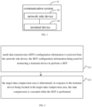
- FIG. 1 is a diagram illustrating an architecture of a communication system according to embodiments of the present invention.
- the communication system may include, but is not limited to, one network side device and one terminal device.
- a number and a form of the devices shown in FIG. 1 are only for example and do not constitute a limitation to embodiments of the present invention, and two or more network side devices and two or more terminal devices may be included in practical applications.
- the communication system as illustrated in FIG. 1 includes one network side device 101 and one terminal device 102 for example.
- a sidelink in embodiments of the invention may be a side link or a direct link.
- the network side device 101 in embodiments of the invention is an entity for transmitting or receiving a signal at a network side.
- the network side device 11 may be an evolved NodeB (eNB), a transmission reception point (TRP), a next generation NodeB (gNB) in a NR system, a base station in other future mobile communication systems, or an access node in a wireless fidelity (WiFi) system.
- eNB evolved NodeB
- TRP transmission reception point
- gNB next generation NodeB
- WiFi wireless fidelity
- a specific technology and a specific device form adopted by the network side device are not limited in embodiments of the present invention.
- the network side device according to embodiments of the present invention may consist of a central unit (CU) and a distributed unit (DU).
- the CU may also be referred to as a control unit.
- the protocol layers of a network side device such as a base station may be split by using a structure of the CU-DU, so that the functions for a part of the protocol layers are placed in the CU for centralized control, and functions of a remaining part or all of the protocol layers are distributed in the DU, and the DU is centrally controlled by the CU.
- the terminal device 102 in embodiments of the invention is an entity for receiving or transmitting a signal at a user side, for example, a mobile phone.
- the terminal device may be referred to as a terminal, a user equipment (UE), a mobile station (MS), a mobile terminal (MT), etc.
- the terminal device may be an automobile with a communication function, a smart automobile, a mobile phone, a wearable device, a tablet computer (Pad), a computer with a wireless transceiver function, a virtual reality (VR) terminal device, an augmented reality (AR) terminal device, a wireless terminal device in industrial control, a wireless terminal device in self-driving, a wireless terminal device in a remote medical surgery, a wireless terminal device in a smart grid, a wireless terminal device in transportation safety, a wireless terminal device in a smart city, a wireless terminal device in a smart home, etc.
- a specific technology adopted by the terminal device and a specific device form adopted by the terminal device are not limited in embodiments of the present invention.
- the network side device configures a bearer of the terminal device to use a small data sending function
- a packet header compression function for example, ROHC or EHC
- How to enable the terminal device to continuously compress data, and how to enable the network side device and terminal device to understand the area where a continuous data compression may be carried out in a same way remain a problem.
- an embodiment of the present invention provides a method for data compression so that for a bearer configured for small data transmission, the network side device and the terminal device have the same understanding of the area where the data compression may be carried out, thus enabling the terminal device to perform the data compression in the target data compression area while performing small data transmission, thus improving a performance of data transmission.
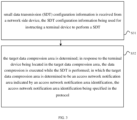
- FIG. 2 is a flowchart illustrating a method for data compression according to embodiments of the present invention.
- the method is executed by a terminal device, which may include, but is not limited to the following steps S21-S22.
- small data transmission (SDT) configuration information is received from the network side device, the SDT configuration information being used for instructing a terminal device to perform an SDT.
- the network side device sends the SDT configuration information to the terminal device, and for example, the network side device instructs the SDT configuration information in an RRCRelease (Radio Resource Control release) message to instruct the terminal device to perform the SDT to send and receive data via the SDT process.
- RRCRelease Radio Resource Control release
- the target data compression area is determined; in response to the terminal device being located in the target data compression area, the data compression is executed while the SDT is performed.
- the terminal device determines the target data compression area, which may be specified by the protocol, or the network side device configures or preconfigures for the terminal device, or the target data compression area is determined from other devices, and embodiments of the present invention do not impose any specific limitations thereon.
- the terminal device after determining the target data compression area, is thus able to execute the data compression while performing the SDT when in the target data compression area.
- executing the data compression while performing the SDT may include the following steps.
- the data compression is executed while the SDT is performed.
- the terminal device executing the data compression may include at least one of the following steps.
- Maintain a compressed state of a decompressed entity is maintained during a PDCP reestablishment.
- RRC radio resource control
- the compressed state of the compressed entity is maintained during the PDCP reestablishment. For example, the compressed entity is not reset or the compression context is retained.
- the compressed state of the decompressed entity is maintained during the PDCP reestablishment. For example, the decompression is not reset or the decompression context is retained.
- the compressed state of the compressed entity is maintained during a PDCP recovery. For example, the compressed entity is not reset or the compression context is retained.
- the compressed state of the decompressed entity is maintained during the PDCP recovery. For example, the decompression is not reset or the decompression context is retained.
- the compressed state of the compressed entity is maintained during the RRC connection recovery. For example, the compressed entity is not reset or the compression context is retained.
- the compressed state of the decompressed entity is maintained during the RRC connection recovery. For example, the decompression is not reset or the decompression context is retained.
- the compressed state of the compressed entity is maintained during the RRC connection release. For example, the compressed entity is not reset or the compression context is retained.
- the compressed state of the decompressed entity is maintained during the RRC connection release. For example, the decompression is not reset or the decompression context is retained.
- a method for data compression is provided in embodiments of the present invention and further includes the following step.
- the data compression is not executed while the SDT is performed.
- the terminal device after determining the target data compression area, is thus able to stop executing the data compression while performing the SDT when in the target data compression area.
- the terminal device stopping executing the data compression may include at least one of the following steps.
- the terminal device may receive the SDT configuration information from the network side device, the SDT configuration information being used for instructing the terminal device to perform the SDT, may determine a target data compression area, and in response to the terminal device being located in the target data compression area, may execute the data compression while performing the SDT. In this way, the terminal device may perform data compression in the target data compression area while performing the SDT, thereby improving the performance of data transmission.
- FIG. 3 is a flowchart illustrating another method for data compression according to embodiments of the present invention.
- the method is executed by a terminal device, and the method may include, but is not limited to the following steps S31-S32.
- small data transmission (SDT) configuration information is received from a network side device, the SDT configuration information being used for instructing a terminal device to perform an SDT.
- step S31 in an embodiment of the present invention may be referred to the relevant description of step S21 in the above example, which will not be repeated herein.
- the target data compression area is determined; in response to the terminal device being located in the target data compression area, the data compression is executed while the SDT is performed; in which the target data compression area is determined to be an access network notification area indicated by an access network notification area identification, the access network notification area identification being specified in the protocol.
- the terminal device determines the target data compression area to be the access network notification area indicated by the access network notification area identification, according to the access network notification area identification specified in the protocol.
- the access network notification area identification specified in the protocol includes any one of the following.
- the access network notification area identification is a notification area identification of an access network to which a cell configured with the CG-SDT resource belongs.
- the access network notification area identification is a notification area identification of an access network to which a cell, in which the terminal device receives a connection suspension message, belongs.
- the access network notification area identification is a notification area identification of an access network to which a cell, in which the terminal device receives a connection release message, belongs.
- the access network notification area identification is the notification area identification of the access network to which a cell configured with the CG-SDT resource belongs.
- the cell configured with the CG-SDT resource is cell #1, and cell #1 belongs to the access network indicated by the access network notification area identification (for example, RNA-1 (RAN-based Notification Area)).
- the access network notification area identification is the notification area identification of the access network to which a cell, in which the terminal device receives a connection suspension message, belongs.
- the cell in which the terminal device receives the connection suspension message is cell #2, and cell #2 belongs to the access network indicated by the access network notification area identification (for example, RNA-1).
- the access network notification area identification is the notification area identification of the access network to which a cell, in which the terminal device receives a connection release message, belongs.
- the cell in which the terminal device receives the connection release message is cell #3, and cell #3 belongs to the access network indicated by the access network notification area identification (for example, RNA-1).
- executing the data compression while performing the SDT may include the following steps.
- the data compression is executed while an SDT is performed.
- the terminal device determines to be in the target data compression area when the cell in which the terminal device currently resides belongs to the access network indicated by the access network notification area identification.
- the terminal device determines to be in the target data compression area when the cell reselected or selected by the terminal device belongs to the access network indicated by the access network notification area identification.
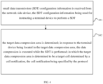
- FIG. 4 is a flowchart illustrating yet another method for data compression according to embodiments of the present invention.
- the method is executed by a terminal device, and the method may include, but is not limited to the following steps S41-S42.
- small data transmission (SDT) configuration information is received from the network side device, the SDT configuration information being used for instructing a terminal device to perform an SDT.
- SDT small data transmission
- step S41 in an embodiment of the present invention may be referred to the relevant description of step S21 in the above example, which will not be repeated herein.
- the target data compression area is determined; in response to the terminal device being located in the target data compression area, the data compression is executed while the SDT is performed; in which the target data compression area is determined to be a target cell determined by a cell notification, the cell notification being specified by the protocol
- the cell notification is specified by the protocol
- the terminal device determines the target data compression area to be the target cell identified by the cell notification, according to the cell notification specified by the protocol.
- executing the data compression while performing the SDT may include the following steps.
- the data compression is executed while the SDT is performed.
- the terminal device determines to be within the target data compression area when the cell in which the terminal device currently resides belongs to the target cell identified by the cell notification.
- the terminal device determines to be within the target data compression area when the cell reselected or selected by the terminal device belongs to the target cell identified by the cell notification.
- the cell notification includes at least one of the following.
- the cell identification is for example cell #1.
- the cell type identification is for example, PCell (Primary Cell), or PSCell (Primary Secondary Cell), or SpCell (Special Cell), or SCell (Secondary Cell), etc.
- the cell notification specified by the protocol includes any of the following.
- the cell notification is a notification which indicates a cell configured with the configured grant-small data transmission (CG-SDT) resources.
- the cell notification is a notification which indicates a cell in which the terminal device receives a connection suspension message.
- the cell notification is a notification which indicates a cell in which the terminal device receives a connection release message.
- the cell in which the terminal device receives the connection suspension message includes any of the following.
- a cell in which the terminal device receives the connection suspension message for a first time is a cell in which the terminal device receives the connection suspension message for a first time.
- a cell in which the terminal device receives the connection suspension message for a last time is a cell in which the terminal device receives the connection suspension message for a last time.
- connection suspension message The cell in which the terminal device successfully receives the connection suspension message will be illustrated.
- the RRCRelease message has 2 segments, segment-1 is sent in cell-1 and segment-2 is sent in cell-2.
- cell-2 is the cell that successfully receives the "connection suspension message" or "connection release message".
- the RRCRelease message has 2 segments, segment-1 is sent in cell-1, and segment-2 is sent in cell-2.
- Cell-1 is the cell that receives the connection suspension message for a first time.
- the RRCRelease message is first transmitted through the hybrid automatic repeat request (HARQ) process 1 in cell-1, and then cell-1 is the cell that receives the connection suspension message for a first time.
- HARQ hybrid automatic repeat request
- the RRCRelease message has 2 segments, segment-1 is sent in cell-1 and segment-2 is sent in cell-2.
- the cell-2 is the cell that receives the connection suspension message for a last time.
- the RRCRelease message is transmitted for the last time through the HARQ process 1 in cell-2, or, the terminal device successfully receives the RRCRelease message through the HARQ process 1 in cell-2, and then cell-2is the cell that receives the connection suspension message for a last time.
- the cell in which the terminal device receives the connection release message includes any of the following.
- a cell in which the terminal device receives the connection release message for a first time is a cell in which the terminal device receives the connection release message for a first time.
- a cell in which the terminal device receives the connection release message for a last time is a cell in which the terminal device receives the connection release message for a last time.
- the RRCRelease message has 2 segments, segment-1 is sent in cell-1 and segment-2 is sent in cell-2.
- cell-2 is the cell that successfully receives the connection release message.
- the RRCRelease message has 2 segments, segment-1 is sent in cell-1 and segment-2 is sent in cell-2.
- Cell-1 is the cell that receives the connection release message for a first time.
- the RRCRelease message is first transmitted through the HARQ process 1 in cell-1, and cell-1 is the cell that receives the connection release message for a first time.
- the RRCRelease message has 2 segments, segment-1 is sent in cell-1 and segment-2 is sent in cell-2.
- Cell-2 is the cell that receives the connection release message for a last time.
- the RRCRelease message is transmitted for the last time through the HARQ process 1 in cell-2, or, the terminal device successfully receives the RRCRelease message through the HARQ process 1 in cell-2, and cell-2 is the cell that receives the connection release message for a last time.
- S41 and S42 may be implemented alone, or may also be implemented in combination with any of the other embodiments in the present invention, for example, with S21 and S22 and/or S31 and S32 in the present invention, and embodiments of the present invention are not specifically limited in this regard.
- FIG. 5 is a flowchart illustrating yet another method for data compression according to embodiments of the present invention.
- the method is applied to the terminal device, and the method may include, but is not limited to the following step S51-552.
- small data transmission (SDT) configuration information is received from the network side device, the SDT configuration information being used for instructing a terminal device to perform an SDT.
- SDT small data transmission
- step S51 in an embodiment of the present invention may be referred to the relevant description of step S21 in the above example, which will not be repeated herein.
- the target data compression area is determined; in response to the terminal device being located in the target data compression area, the data compression is executed while the SDT is performed; the data compression configuration configured by the network side device is received, in which the data compression configuration includes the data compression area configuration; the target data compression area is determined based on the data compression area configuration.
- determining the target data compression area based on the data compression area configuration includes the following steps.
- the target data compression area is determined to be the access network notification area indicated by the access network notification area identification.
- the data compression area configuration is the access network notification area identification
- the terminal device based on the data compression configuration configured by the network side device, determines the target data compression area to be the access network notification area indicated by the access network notification area identification.
- executing the data compression while performing the SDT includes the following steps.
- the data compression is executed while the SDT is performed.
- the terminal device determines to be in the target data compression area when the cell in which the terminal device currently resides belongs to the access network notification area indicated by the access network notification area identification.
- the terminal device determines to be in the target data compression area when the cell in which the terminal device reselected or selected belongs to the access network notification area indicated by the access network notification area identification.
- determining the target data compression area based on the data compression area configuration includes the following steps.
- the target data compression area is determined to be a target cell determined by the cell notification.
- the data compression area configuration is the cell notification
- the terminal device determines the target data compression area to be the target cell determined by the cell notification based on the data compression configuration configured by the network side device.
- executing the data compression while performing the SDT includes the following steps.
- the data compression is executed while the SDT is performed.
- the terminal device determines to be within the target data compression area when the cell in which the terminal device currently resides belongs to the target cell identified by the cell notification.
- the terminal device determines to be within the target data compression area when the cell in which the terminal device reselected or selected belongs to the target cell identified by the cell notification.
- the cell notification includes at least one of the following.
- the cell identification is for example cell #1.
- the cell type identification is for example PCell (Primary Cell), or PSCell (Primary Secondary Cell), or SpCell (Special Cell), or SCell (Secondary Cell), and etc.
- the data compression configuration further includes the following.
- a data compression bearer configuration and a data compression type configuration are described.
- the data compression bearer configuration includes at least one of the following.
- the bearer type corresponding to the data compression is for example, MCG (Master Cell Group) or SCG (Secondary Cell Group) bearer.
- the bearer identification corresponding to the data compression is for example DRB-1 (Data Radio Bearer).
- the data compression type configuration includes at least one of the following.
- the type indication corresponding to the data compression is for example, EHC, or ROHC, etc.
- the indication that the data compression continues and the indication that the data compression stops are for example, drb-ContinueEHC, or drb-ContinueROHC, etc.
- the indication of a direction of the data compression is for example, drb-ContinueEHC-UL or drb-ContinueROHC-UL, or drb-ContinueEHC-DL or drb-ContinueROHC-DL, or drb-ContinueEHC or drb-ContinueROHC, etc.
- the terminal device stops executing the data compression includes at least one of the following.
- Releasing the data compression configuration or deleting the data compression configuration is for example deleting the drb-ContinueROHC configuration.
- Releasing a compression context corresponding to the data compression configuration or deleting a compression context corresponding to the data compression configuration is for example deleting the compression context of the ROHC entity.
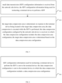
- FIG. 6 is a flowchart illustrating yet another method for data compression according to embodiments of the present invention.
- the method is applied to the network side device, and the method may include, but is not limited to the following step S61.
- SDT configuration information used for instructing a terminal device to perform the SDT is sent to the terminal device; the data compression configuration is sent to the terminal device; in which the data compression configuration includes a data compression area configuration.
- the network side device sends the SDT configuration information to the terminal device.
- the network side device indicates the SDT configuration information in an RRCRelease (Radio Resource Control release) message to instruct the terminal device to perform the SDT so as to send and receive data through the SDT process.
- RRCRelease Radio Resource Control release
- the terminal device may receive small data transmission (SDT) configuration information from a network side device, the SDT configuration information being used for instructing the terminal device to perform the SDT, and the terminal device may receive the data compression configuration configured by the network side device, in which the data compression configuration includes the data compression area configuration.
- SDT small data transmission
- the terminal device may determine the target data compression area based on the data compression area configuration; and when the terminal device is located in the target data compression area, the data compression is executed while the SDT is performed. In this way, the terminal device may perform data compression in the target data compression area while performing the SDT, thus improving the performance of data transmission.
- the data compression configuration includes at least one of the following.
- An access network notification area identification An access network notification area identification.
- the network side device sends the data compression configuration to the terminal device, in which the data compression configuration includes the data compression area configuration.
- the data compression area configuration includes: the access network notification area identification; or the cell notification, or the access network notification area identification and the cell notification.
- the data compression area configuration is the access network notification area identification
- the terminal device based on the data compression configuration configured in the network side device, determines the target data compression area to be the access network notification area indicated by the access network notification area identification.
- the data compression area configuration is the cell notification
- the terminal device determines the target data compression area to be the target cell determined by the cell notification based on the data compression configuration configured by the network side device.
- the cell notification includes at least one of the following.
- the cell identification is for example cell #1.
- the cell type identification is for example, PCell (Primary Cell), or PSCell (Primary Secondary Cell), or SpCell (Special Cell), or SCell (Secondary Cell), and etc.
- the data compression configuration further includes the following.
- a data compression bearer configuration and a data compression type configuration are described.
- the data compression bearer configuration includes at least one of the following.
- the bearer type corresponding to the data compression is for example MCG (Master Cell Group) or SCG (Secondary Cell Group) bearer.
- the bearer identification corresponding to the data compression is for example DRB-1 (Data Radio Bearer).
- the data compression type configuration includes at least one of the following.
- the type indication corresponding to the data compression is for example, EHC, or ROHC, etc.
- the indication that the data compression continues and the indication that the data compression stops are for example, drb-ContinueEHC, or drb-ContinueROHC, etc.
- the indication of a direction of the data compression is for example, drb-ContinueEHC-UL or drb-ContinueROHC-UL, or drb-ContinueEHC-DL or drb-ContinueROHC-DL, or drb-ContinueEHC or drb-ContinueROHC, etc.
- the methods in embodiments of the present invention are described from the perspectives of the network side device and the terminal device, respectively.
- the network side device and the terminal device may include a hardware structure, a software module, so that each of the above examples of embodiments functions is implemented in the form of a hardware structure, a software module, or a hardware structure plus a software module.
- a function of each of the above functions may be performed in the form of the hardware structure, the software module, or the hardware structure plus the software module.
- FIG. 7 is a structure diagram illustrating a communication apparatus 1 according to embodiments of the present invention.
- the communication apparatus 1 shown in FIG. 7 may include a transceiver module 11 and a processing module 12.
- the transceiver module 11 may include a transmitting module and/or a receiving module, the transmitting module is for realizing a transmitting function, and the receiving module is for realizing a receiving function, and the transceiver module 11 may realize the transmitting function and/or the receiving function.
- the communication apparatus 1 may be a terminal device, an apparatus in the terminal device, or an apparatus to be used together with the terminal device.
- the communication apparatus 10 is the terminal device and includes a transceiver module 11 and a processing module 12.
- the transceiver module 11 is configured to receive SDT configuration information from a network side device, the SDT configuration information being used for instructing a terminal device to perform the SDT.
- the processing module 12 is configured to determine a target data compression area; and in response to the terminal device being located in the target data compression area, to execute data compression while performing the SDT.
- the processing module 12 is further configured to, in response to the terminal device being not located in the target data compression area, stop executing data compression while performing the SDT.
- the processing module 12 is specifically configured to determine the target data compression area according to a protocol.
- the processing module 12 is specifically configured to determine the target data compression area to be an access network notification area indicated by an access network notification area identification, the access network notification area identification being specified in the protocol.
- the access network notification area identification specified in the protocol includes any one of the following.
- the access network notification area identification is a notification area identification of an access network to which a cell configured with the CG-SDT resource belongs.
- the access network notification area identification is a notification area identification of an access network to which a cell, in which the terminal device receives a connection suspension message, belongs.
- the access network notification area identification is a notification area identification of an access network to which a cell, in which the terminal device receives a connection release message, belongs.
- the processing module 12 is specifically configured to determine the target data compression area to be a target cell determined by a cell notification, the cell notification being specified by the protocol.
- the cell notification includes at least one of the following.
- the cell notification specified in the protocol includes any one of the following.
- the cell notification is a notification which indicates a cell configured with the configured grant-small data transmission (CG-SDT) resources.
- the cell notification is a notification which indicates a cell in which the terminal device receives a connection suspension message.
- the cell notification is a notification indicating a cell in which the terminal device receives a connection release message.
- the cell in which the terminal device receives the connection suspension message includes any one of the following.
- a cell in which the terminal device receives the connection suspension message for a first time is a cell in which the terminal device receives the connection suspension message for a first time.
- a cell in which the terminal device receives the connection suspension message for a last time is a cell in which the terminal device receives the connection suspension message for a last time.
- the cell in which the terminal device receives the connection release message includes any of the following.
- a cell in which the terminal device receives the connection release message for a first time is a cell in which the terminal device receives the connection release message for a first time.
- a cell in which the terminal device receives the connection release message for a last time is a cell in which the terminal device receives the connection release message for a last time.
- the processing module 12 is specifically configured to receive the data compression configuration configured by the network side device, in which the data compression configuration comprises the data compression area configuration; to determine the target data compression area based on the data compression area configuration.
- the processing module 12 is specifically configured to, in case the data compression area configuration is an access network notification area identification, determine the target data compression area to be the access network notification area indicated by the access network notification area identification.
- the processing module 12 is specifically configured to, in case the data compression area configuration is a cell notification, determine the target data compression area to be a target cell determined by the cell notification.
- the cell notification includes at least one of the following.
- the data compression configuration further includes the following.
- a data compression bearer configuration and a data compression type configuration are described.
- the data compression bearer configuration includes at least one of the following.
- the data compression type configuration includes at least one of the following.
- the processing module 12 is specifically configured to, in response to a cell in which the terminal device currently resides, or a cell reselected, or a cell selected, or a type of the access network reselected belonging to the target data compression area, execute the data compression while performing the SDT.
- the processing module 12 is specifically configured to execute the data compression, including at least one of the following.
- RRC radio resource control
- the processing module 12 is specifically configured to stop executing the data compression, and includes at least one of the following.
- the processing module 12 is specifically configured to stop executing the data compression, and includes at least one of the following.
- the communication apparatus 1 may be the network side device, or an apparatus in the network side device, or an apparatus to be used together with the network side device.
- the communication apparatus 1 is the network side device and includes a transceiver module 11.
- the transceiver module 11 is configured to send, to the terminal device, SDT configuration information used for instructing a terminal device to perform the SDT; to send the data compression configuration to the terminal device, in which the data compression configuration comprises a data compression area configuration.
- the data compression area configuration includes at least one of the following.
- An access network notification area identification An access network notification area identification.
- the cell notification includes at least one of the following.
- the data compression configuration further includes the following.
- a data compression bearer configuration and a data compression type configuration are described.
- the data compression bearer configuration includes at least one of the following.
- the data compression type configuration includes at least one of the following.
- the communication apparatus 1 provided in the above embodiments of the present invention achieves the same or similar beneficial effects as the method for configuring resources provided in some of the above embodiments, which will not be described in detail herein.
- FIG. 8 is a structure diagram illustrating another communication apparatus 1000 according to embodiments of the present invention.
- the communication apparatus 1000 may be a network side device, a terminal device, a chip, a system on chip or a processor that supports the network side device to implement the method, or a chip, a system on chip or a processor that supports the terminal device to implement the method.
- the apparatus 1000 may be configured to implement the method described in the method embodiments, and reference is made to the description of the method embodiments.
- the communication apparatus 1000 may include one or more processors 1001.
- the processor 1001 may include a general purpose processor or a dedicated processor.
- the processor 1001 may be a baseband processor or a central processor.
- the baseband processor may be configured to process a communication protocol and communication data
- the central processor may be configured to control a communication apparatus (e.g., a base station, a baseband chip, a terminal device, a terminal device chip, a DU or CU, etc.), to execute a computer program, and process data of the computer program.
- a communication apparatus e.g., a base station, a baseband chip, a terminal device, a terminal device chip, a DU or CU, etc.
- the communication apparatus 1000 may further include one or more memories 1002 with a computer program 1004 stored thereon.
- the memory 1002 executes the computer program 1004 so that the communication apparatus 1000 performs the method as described in the above method embodiments.
- the memory 1002 may further store data.
- the communication apparatus 1000 and the memory 1002 may be independently configured or integrated together.
- the communication apparatus 1000 may further include a transceiver 1005 and an antenna 1006.
- the transceiver 1005 may be referred to as a transceiving unit, a transceiver or a transceiving circuit, which may be configured to achieve a transceiving function.
- the transceiver 1005 may include a receiver and a transmitter.
- the receiver may be referred to as a receiver or a receiving circuit, etc., for implementing a receiving function;
- the transmitter may be referred to as a transmitter or a transmitting circuit, etc. for implementing a transmitting function.
- the communication apparatus 1000 may further include one or more interface circuits 1007.
- the interface circuit 1007 is configured to receive code instructions and transmit the code instructions to the processor 1001.
- the processor 1001 runs the code instructions so that the communication apparatus 1000 performs the method according to the above method embodiment.
- the communication apparatus 1000 is a terminal device.
- the transceiver 1005 is configured to execute step S21 in FIG.2 ; step S31 in FIG. 3 ; step S41 in FIG. 4 ; step S41 in FIG. 4 ; the processor 1001 is configured to execute step S22 in FIG.2 ; step S32 in FIG.3 ; step S42 in FIG.4 ; step S52 in FIG.5 .
- the communication apparatus 1000 is a network side device.
- the transceiver 1005 is configured to execute step S61 in FIG.6 .
- the processor 1001 may include a transceiver configured to implement receiving and transmitting functions.
- the transceiver may be a transceiving circuit, or an interface, or an interface circuit.
- the transceiving circuit, the interface or the interface circuit configured to implement receiving and transmitting functions may be separate or integrated together.
- the transceiving circuit, the interface or the interface circuit may be configured to read and write codes/data, or the transceiving circuit, the interface or the interface circuit may be configured to transmit or deliver a signal.
- the processor 1001 may be stored with a computer program 1003.
- the computer program 1003 runs on the processor 1001 so that the communication apparatus 1000 performs the method as described in the above method embodiments.
- the computer program 1003 may be solidified in the processor 1001, in which case the processor 1001 may be implemented by a hardware.
- the communication apparatus 1000 may include a circuit that may implement a transmitting or receiving or communication function of the above method embodiments.
- the processor and the transceiver described in the present invention may be implemented on integrated circuits (ICs), analog ICs, radio frequency integrated circuits (RFICs), mixed signal ICs, application specific integrated circuits (ASICs), printed circuit boards (PCBs), electronic devices, etc.
- the processor and the transceiver may further be fabricated by using various IC process technologies, such as complementary metal oxide semiconductor (CMOS), n-type Metal-oxide-semiconductor (NMOS), positive channel metal oxide semiconductor (PMOS), bipolar junction transistor(BJT), bipolar CMOS(BiCMOS), silicon germanium(SiGe) and gallium arsenide(GaAs).
- CMOS complementary metal oxide semiconductor
- NMOS n-type Metal-oxide-semiconductor
- PMOS positive channel metal oxide semiconductor
- BJT bipolar junction transistor
- BiCMOS bipolar CMOS
- SiGe silicon germanium
- GaAs gallium arsenide
- the communication apparatus described in the above embodiments may be a network device or a terminal device, but the scope of the communication apparatus described in the present invention is not limited thereto, and a structure of the communication apparatus may not be subject to FIG. 8 .
- the communication apparatus may be a stand-alone device or may be a part of a larger device.
- the communication apparatus may be the following.
- the communication apparatus may be a chip or a system on chip
- Chip 1100 includes a processor 1101 and an interface 1103, in which the number of processors 1101 may be one or more and the number of interfaces 1103 may be more than one.
- Interface 1103 is for receiving code instructions and sending code instructions to the processor.
- Processor 1101 is for running code instructions to perform a method for data compression as described in some embodiments above.
- the interface 1103 is for receiving code instructions and sending them to said processor.
- the processor 1101 is for running code instructions to perform a method for data compression as described in some embodiments above.
- the chip 1100 further includes a memory 1102 configured to save necessary computer program and data.
- a system for configuring resources is further provided in embodiments of the invention.
- the system includes a communication apparatus as a terminal device and a communication apparatus as a network side device in the preceding embodiment of FIG. 7 , or, alternatively, the system includes a communication apparatus as a terminal device and a communication apparatus as a network side device in the preceding embodiment of FIG. 8 .
- a readable storage medium with instructions stored thereon is further provided in the invention. When the instructions are executed by a computer, steps of any one of the method embodiment are implemented.
- a computer program product is further provided in the invention.
- the computer program product implements functions of the above any one method embodiment when executed by a processor.
- the functions may be wholly or partially implemented by a software, a hardware, a firmware, or any combination thereof.
- the functions When implemented by a software, the functions may be implemented in whole or in part in the form of a computer program product.
- the computer program product includes one or more computer programs. Procedures or functions according to embodiments of the present invention are wholly or partially generated when the computer program is loaded and executed on a computer.
- the computer may be a general purpose computer, a special purpose computer, a computer network, or other programmable device.
- the computer program may be stored in a computer-readable storage medium or transmitted from one computer-readable storage medium to another.
- the computer program may be transmitted from one website, computer, server, or data center to another via wire (such as a coaxial cable, a fiber optic, a digital subscriber line (DSL)) or wireless (such as infrared, wireless, microwave).
- the computer-readable storage medium may be any available medium that may be accessed by a computer or a data storage device such as a server that integrates one or more of the available media, and a data center.
- the readable medium may be a magnetic medium (such as a floppy disk, a hard disk and a magnetic tape), an optical medium (such as a digital video disk (DVD)), or a semiconductor medium (such as a solid state disk (SSD)).
- At least one in the present invention may also be described as one or more, and a plurality of may be two, three, four or more, which is not limited in the present invention.
- technical features in the kind of technical feature are distinguished by “first” , “second”, “third” , “A” , “B” , “C” and “D " , and there is no order of precedence or magnitude between technical features described in “first”, “second”, “third”, “A”, “B”, “C” and “D” .
- Corresponding relationships indicated by tables in the present invention may be configured or predefined. Values of information in tables are only examples, and may be configured as other values, which are not limited in the invention. When corresponding relationships between information and parameters are configured, it is not always necessary to configure all corresponding relationships indicated in tables. For example, in the tables in the present invention, corresponding relationships indicated by some rows may not be configured. For another example, appropriate transformations and adjustments, such as splitting and merging, may be made based on the above tables. Names of parameters shown in headers in the tables may be other names understandable by the communication apparatus, and values or representations of the parameters may be other values or representations understandable by the communication apparatus. When the above tables are implemented, other data structures may be used, and for example, arrays, queues, containers, stacks, linear lists, pointers, linked lists, trees, graphs, structures, classes, heaps or hash tables may be used.
- Predefined in the invention may be understood as defined, predefined, stored, prestored, pre-negotiated, pre-configured, solidified or pre-fired.
Landscapes
- Engineering & Computer Science (AREA)
- Computer Networks & Wireless Communication (AREA)
- Signal Processing (AREA)
- Computer Security & Cryptography (AREA)
- Theoretical Computer Science (AREA)
- Mobile Radio Communication Systems (AREA)
Applications Claiming Priority (1)
| Application Number | Priority Date | Filing Date | Title |
|---|---|---|---|
| PCT/CN2022/070565 WO2023130321A1 (zh) | 2022-01-06 | 2022-01-06 | 一种数据压缩方法和装置 |
Publications (2)
| Publication Number | Publication Date |
|---|---|
| EP4462935A1 true EP4462935A1 (de) | 2024-11-13 |
| EP4462935A4 EP4462935A4 (de) | 2025-03-26 |
Family
ID=87072959
Family Applications (1)
| Application Number | Title | Priority Date | Filing Date |
|---|---|---|---|
| EP22917796.9A Pending EP4462935A4 (de) | 2022-01-06 | 2022-01-06 | Verfahren und vorrichtung zur datenkomprimierung |
Country Status (4)
| Country | Link |
|---|---|
| US (1) | US20250112978A1 (de) |
| EP (1) | EP4462935A4 (de) |
| CN (1) | CN116724655A (de) |
| WO (1) | WO2023130321A1 (de) |
Family Cites Families (3)
| Publication number | Priority date | Publication date | Assignee | Title |
|---|---|---|---|---|
| WO2020087280A1 (en) * | 2018-10-30 | 2020-05-07 | Qualcomm Incorporated | Configurations for small data transmission |
| PL4026391T3 (pl) * | 2020-02-13 | 2024-10-28 | Canon Kabushiki Kaisha | Transmisja małych danych (SDT) |
| CN113853028B (zh) * | 2020-06-25 | 2024-07-12 | 上海朗帛通信技术有限公司 | 一种被用于无线通信的通信节点中的方法和装置 |
-
2022
- 2022-01-06 WO PCT/CN2022/070565 patent/WO2023130321A1/zh not_active Ceased
- 2022-01-06 US US18/727,003 patent/US20250112978A1/en active Pending
- 2022-01-06 EP EP22917796.9A patent/EP4462935A4/de active Pending
- 2022-01-06 CN CN202280000028.8A patent/CN116724655A/zh active Pending
Also Published As
| Publication number | Publication date |
|---|---|
| WO2023130321A1 (zh) | 2023-07-13 |
| US20250112978A1 (en) | 2025-04-03 |
| EP4462935A4 (de) | 2025-03-26 |
| CN116724655A (zh) | 2023-09-08 |
Similar Documents
| Publication | Publication Date | Title |
|---|---|---|
| US20240388999A1 (en) | System information transmission method and apparatus | |
| US20240297702A1 (en) | Channel state feedback method and apparatus | |
| CN115552968A (zh) | 成功切换报告shr的记录上报方法和装置 | |
| CN115669181A (zh) | 一种确定触发连续lbt失败的方法及装置 | |
| CN115336330A (zh) | 数据传输配置方法和装置 | |
| EP4447558A1 (de) | Zugangssteuerungsverfahren und -vorrichtung | |
| EP4668631A1 (de) | Verfahren und vorrichtung zur konfiguration eines harq-prozesses | |
| CN114287166A (zh) | 一种基于四步随机接入的第三条消息重复的覆盖增强方法 | |
| EP4507376A1 (de) | Aktualisierungsverfahren und -vorrichtung für zellgruppen einer endgerätevorrichtung in dualer konnektivität | |
| US20250317827A1 (en) | Method and apparatus for transmitting data forwarding information | |
| EP4462935A1 (de) | Verfahren und vorrichtung zur datenkomprimierung | |
| EP4507377A1 (de) | Verfahren zur steuerung der freigabe eines quellsekundärknotens und vorrichtung | |
| EP4496411A1 (de) | Verfahren zur anforderung von systeminformationen und vorrichtung dafür | |
| US20240276281A1 (en) | Measurement gap scheduling method and apparatus therefor | |
| CN115669182A (zh) | 一种上报方法/装置/设备及存储介质 | |
| CN116636166A (zh) | 一种连续先听后说lbt失败的处理方法及其装置 | |
| WO2024045042A1 (zh) | 一种能力交互触发方法/装置/设备及存储介质 | |
| CN115516916A (zh) | 一种上报方法、装置、设备及存储介质 | |
| CN116097612A (zh) | 信息上报方法和装置 | |
| US12598584B2 (en) | Paging processing method, communication apparatus, and storage medium | |
| EP4550924A1 (de) | Übertragungssteuerungsverfahren und -vorrichtung | |
| EP4712549A1 (de) | Verfahren und vorrichtung zur erkennung von sidelink-funkverbindungsfehlern | |
| EP4539581A1 (de) | Zugangssteuerungsverfahren und -vorrichtung | |
| EP4507386A1 (de) | Verfahren zur unterdrückung einer cpc-konfiguration oder einer cpa-konfiguration und vorrichtung dafür | |
| US20250294419A1 (en) | Methods for cross-base station cell configuration |
Legal Events
| Date | Code | Title | Description |
|---|---|---|---|
| STAA | Information on the status of an ep patent application or granted ep patent |
Free format text: STATUS: THE INTERNATIONAL PUBLICATION HAS BEEN MADE |
|
| PUAI | Public reference made under article 153(3) epc to a published international application that has entered the european phase |
Free format text: ORIGINAL CODE: 0009012 |
|
| STAA | Information on the status of an ep patent application or granted ep patent |
Free format text: STATUS: REQUEST FOR EXAMINATION WAS MADE |
|
| 17P | Request for examination filed |
Effective date: 20240725 |
|
| AK | Designated contracting states |
Kind code of ref document: A1 Designated state(s): AL AT BE BG CH CY CZ DE DK EE ES FI FR GB GR HR HU IE IS IT LI LT LU LV MC MK MT NL NO PL PT RO RS SE SI SK SM TR |
|
| A4 | Supplementary search report drawn up and despatched |
Effective date: 20250220 |
|
| RIC1 | Information provided on ipc code assigned before grant |
Ipc: H04L 69/04 20220101ALI20250214BHEP Ipc: H04W 74/08 20240101AFI20250214BHEP |
|
| DAV | Request for validation of the european patent (deleted) | ||
| DAX | Request for extension of the european patent (deleted) | ||
| RIC1 | Information provided on ipc code assigned before grant |
Ipc: H04W 74/08 20240101AFI20251210BHEP Ipc: H04L 69/04 20220101ALI20251210BHEP |
|
| GRAP | Despatch of communication of intention to grant a patent |
Free format text: ORIGINAL CODE: EPIDOSNIGR1 |
|
| STAA | Information on the status of an ep patent application or granted ep patent |
Free format text: STATUS: GRANT OF PATENT IS INTENDED |
|
| INTG | Intention to grant announced |
Effective date: 20260121 |