EP4464128B1 - Filament à del pour éclairage et désinfection - Google Patents
Filament à del pour éclairage et désinfection Download PDFInfo
- Publication number
- EP4464128B1 EP4464128B1 EP22838885.6A EP22838885A EP4464128B1 EP 4464128 B1 EP4464128 B1 EP 4464128B1 EP 22838885 A EP22838885 A EP 22838885A EP 4464128 B1 EP4464128 B1 EP 4464128B1
- Authority
- EP
- European Patent Office
- Prior art keywords
- leds
- led
- light
- led filament
- iled
- Prior art date
- Legal status (The legal status is an assumption and is not a legal conclusion. Google has not performed a legal analysis and makes no representation as to the accuracy of the status listed.)
- Active
Links
Images


Classifications
-
- H—ELECTRICITY
- H05—ELECTRIC TECHNIQUES NOT OTHERWISE PROVIDED FOR
- H05B—ELECTRIC HEATING; ELECTRIC LIGHT SOURCES NOT OTHERWISE PROVIDED FOR; CIRCUIT ARRANGEMENTS FOR ELECTRIC LIGHT SOURCES, IN GENERAL
- H05B45/00—Circuit arrangements for operating light-emitting diodes [LED]
- H05B45/10—Controlling the intensity of the light
-
- F—MECHANICAL ENGINEERING; LIGHTING; HEATING; WEAPONS; BLASTING
- F21—LIGHTING
- F21K—NON-ELECTRIC LIGHT SOURCES USING LUMINESCENCE; LIGHT SOURCES USING ELECTROCHEMILUMINESCENCE; LIGHT SOURCES USING CHARGES OF COMBUSTIBLE MATERIAL; LIGHT SOURCES USING SEMICONDUCTOR DEVICES AS LIGHT-GENERATING ELEMENTS; LIGHT SOURCES NOT OTHERWISE PROVIDED FOR
- F21K9/00—Light sources using semiconductor devices as light-generating elements, e.g. using light-emitting diodes [LED] or lasers
- F21K9/20—Light sources comprising attachment means
- F21K9/23—Retrofit light sources for lighting devices with a single fitting for each light source, e.g. for substitution of incandescent lamps with bayonet or threaded fittings
- F21K9/238—Arrangement or mounting of circuit elements integrated in the light source
-
- F—MECHANICAL ENGINEERING; LIGHTING; HEATING; WEAPONS; BLASTING
- F21—LIGHTING
- F21K—NON-ELECTRIC LIGHT SOURCES USING LUMINESCENCE; LIGHT SOURCES USING ELECTROCHEMILUMINESCENCE; LIGHT SOURCES USING CHARGES OF COMBUSTIBLE MATERIAL; LIGHT SOURCES USING SEMICONDUCTOR DEVICES AS LIGHT-GENERATING ELEMENTS; LIGHT SOURCES NOT OTHERWISE PROVIDED FOR
- F21K9/00—Light sources using semiconductor devices as light-generating elements, e.g. using light-emitting diodes [LED] or lasers
- F21K9/20—Light sources comprising attachment means
- F21K9/23—Retrofit light sources for lighting devices with a single fitting for each light source, e.g. for substitution of incandescent lamps with bayonet or threaded fittings
- F21K9/232—Retrofit light sources for lighting devices with a single fitting for each light source, e.g. for substitution of incandescent lamps with bayonet or threaded fittings specially adapted for generating an essentially omnidirectional light distribution, e.g. with a glass bulb
-
- F—MECHANICAL ENGINEERING; LIGHTING; HEATING; WEAPONS; BLASTING
- F21—LIGHTING
- F21Y—INDEXING SCHEME ASSOCIATED WITH SUBCLASSES F21K, F21L, F21S and F21V, RELATING TO THE FORM OR THE KIND OF THE LIGHT SOURCES OR OF THE COLOUR OF THE LIGHT EMITTED
- F21Y2103/00—Elongate light sources, e.g. fluorescent tubes
- F21Y2103/10—Elongate light sources, e.g. fluorescent tubes comprising a linear array of point-like light-generating elements
-
- F—MECHANICAL ENGINEERING; LIGHTING; HEATING; WEAPONS; BLASTING
- F21—LIGHTING
- F21Y—INDEXING SCHEME ASSOCIATED WITH SUBCLASSES F21K, F21L, F21S and F21V, RELATING TO THE FORM OR THE KIND OF THE LIGHT SOURCES OR OF THE COLOUR OF THE LIGHT EMITTED
- F21Y2113/00—Combination of light sources
- F21Y2113/10—Combination of light sources of different colours
- F21Y2113/13—Combination of light sources of different colours comprising an assembly of point-like light sources
- F21Y2113/17—Combination of light sources of different colours comprising an assembly of point-like light sources forming a single encapsulated light source
-
- F—MECHANICAL ENGINEERING; LIGHTING; HEATING; WEAPONS; BLASTING
- F21—LIGHTING
- F21Y—INDEXING SCHEME ASSOCIATED WITH SUBCLASSES F21K, F21L, F21S and F21V, RELATING TO THE FORM OR THE KIND OF THE LIGHT SOURCES OR OF THE COLOUR OF THE LIGHT EMITTED
- F21Y2115/00—Light-generating elements of semiconductor light sources
- F21Y2115/10—Light-emitting diodes [LED]
-
- H—ELECTRICITY
- H05—ELECTRIC TECHNIQUES NOT OTHERWISE PROVIDED FOR
- H05B—ELECTRIC HEATING; ELECTRIC LIGHT SOURCES NOT OTHERWISE PROVIDED FOR; CIRCUIT ARRANGEMENTS FOR ELECTRIC LIGHT SOURCES, IN GENERAL
- H05B45/00—Circuit arrangements for operating light-emitting diodes [LED]
- H05B45/20—Controlling the colour of the light
-
- H—ELECTRICITY
- H05—ELECTRIC TECHNIQUES NOT OTHERWISE PROVIDED FOR
- H05B—ELECTRIC HEATING; ELECTRIC LIGHT SOURCES NOT OTHERWISE PROVIDED FOR; CIRCUIT ARRANGEMENTS FOR ELECTRIC LIGHT SOURCES, IN GENERAL
- H05B45/00—Circuit arrangements for operating light-emitting diodes [LED]
- H05B45/30—Driver circuits
- H05B45/357—Driver circuits specially adapted for retrofit LED light sources
Definitions
- the present invention generally relates to lighting arrangements comprising one or more light emitting diodes, LEDs. More specifically, the present invention is related to provide a combination of a disinfection (bactericidal and/or viricidal) lighting effect and an aesthetically desirable (general) illumination.
- LED light emitting diodes
- LEDs provide numerous advantages such as a longer operational life, a reduced power consumption, and an increased efficiency related to the ratio between light energy and heat energy.
- LED filament lamps are highly appreciated as they are very decorative.
- LEDs Due to the advantageous aspects of the use of LEDs, the interest has rapidly increased to replace conventional light sources with LEDs in many lighting arrangements. It will be appreciated that this replacement, also called retrofitting, is appreciated and desired by users who wish to have the look of an incandescent bulb.
- the light source replacement is often performed by removing the conventional light source(s) from the luminaire (e.g. a lamp holder) of the lighting arrangement and attaching the LEDs, LED arrangement(s) or LED device(s) into the luminaire.
- the luminaire e.g. a lamp holder
- UVA 315-400 nm
- violet light 400-420 nm
- WO 2021/018606 discloses a light emitting diode, LED, filament arrangement.
- the LED filament arrangement comprises a LED filament comprising an array of a plurality of light emitting diodes.
- the LED filament comprises a first subset of at least two LEDs, and a second subset of at least two LEDs, wherein the first subset of LEDs is different from the second subset of LEDs.
- the LEDs of the first subset are coupled in series and the LEDs of the second subset differs from the luminous flux of the individual LEDs of the second subset during operation of the LED filament arrangement.
- a light emitting diode, LED, filament configured to emit LED filament light.
- the LED filament comprises an array of a plurality of light emitting diodes, LEDs, configured to emit first LED light.
- the LED filament further comprises circuitry coupled to the plurality of LEDs.
- the LED filament further comprises a carrier arranged to support the plurality of LEDs.
- the LED filament further comprises an encapsulant comprising a translucent material.
- the encapsulant further comprises a luminescent material configured to at least partially convert the LED light into converted light.
- the encapsulant at least partially encloses the plurality of LEDs and (at least partially encloses) the carrier.
- the plurality of LEDs comprises a first set of LEDs arranged to emit first LED light in a first wavelength range of 430-490 nm, and a second set of LEDs arranged to emit second LED light in a second wavelength range of 315-420 nm.
- the circuitry is configured to provide the first set of LEDs with a first current, I c1 , and to provide the second set of LEDs with a second current, I c2 , during operation of the LED filament, wherein I c2 > I c1 .
- the present invention is based on the idea of providing a LED filament wherein a first set of LEDs are arranged to emit predominantly blue light and a second set of LEDs are arranged to emit predominantly UV and/or violet light.
- the blue light is (at least partially) converted into typically yellow and/or red light to obtain (extremely) warm white light, such as 1800-2500 K, whereas the UV and/or violet light provides a disinfection effect, i.e. an inactivation of bacteria.
- the present invention is further advantageous in that the encapsulant of the LED filament is able to provide a desired light output, comprising a desired (omnidirectional) distribution of the light as well as being able to provide an aesthetically decorative or appealing lighting effect.
- the LED filament of the present invention furthermore comprises relatively few components.
- the relatively low number of components is advantageous in that the LED filament is relatively inexpensive to fabricate.
- the relatively low number of components of the LED filament implies an easier recycling, especially compared to devices or arrangements comprising a relatively high number of components which impede an easy disassembling and/or recycling operation.
- the LED filament which is configured or arranged to emit LED filament light, comprises an array of a plurality of LEDs which are configured or arranged to emit LED light. It will be appreciated that the LED filament light may comprise the LED light and/or the LED light as affected (e.g. scattered and/or converted) by the encapsulant of the LED filament.
- array it is here meant a linear arrangement or chain of LEDs, or the like, arranged on the LED filament.
- the LED filament further comprises circuitry coupled to the plurality of LEDs.
- circuitry it is here meant one or more electrical circuits which is (are) configured for a supply of electrical power to the plurality of LEDs.
- the LED filament further comprises a carrier arranged to support the plurality of LEDs.
- the plurality of LEDs may be arranged, mounted and/or mechanically coupled on/to a carrier (e.g. a substrate), wherein the carrier is configured to mechanically and/or electrically support the LEDs.
- the carrier may be light transmissive and/or reflective.
- the carrier may furthermore be elongated in order to support the array of LEDs of the (elongated) LED filament.
- the LED filament further comprises an encapsulant.
- encapsulant it is here meant a material, element, arrangement, or the like, which is configured or arranged to at least partially surround, encapsulate and/or enclose the plurality of LEDs, the carrier and the at least one heat sink of the LED filament.
- the encapsulant comprises a translucent material.
- translucent material it is here meant a material, composition and/or substance which is translucent and/or transparent for visible light.
- the encapsulant further comprises a luminescent material configured to at least partly convert the LED light emitted from the plurality of LEDs into converted light.
- the encapsulant at least partially encloses the plurality of LEDs and the carrier.
- the plurality of LEDs comprises a first set of LEDs arranged to emit first LED light in a first wavelength range of 430-490 nm. Hence, the first set of LEDs is arranged or configured to emit first LED light which is predominantly blue.
- the plurality of LEDs further comprises a second set of LEDs arranged to emit second LED light in a second wavelength range of 315-420 nm (especially for second LED light in a second wavelength range of 315-360 and/or 400-420 nm).
- the second set of LEDs is arranged or configured to emit second LED light which is predominantly violet and/or ultraviolet (UV).
- the circuitry is configured to provide the first set of LEDs with a first current, I c1 , and to provide the second set of LEDs with a second current, I c2 , during operation of the LED filament, wherein I c2 > I c1 .
- the circuitry of the LED filament is configured to provide a higher current to the violet LEDs compared to the blue LEDs during operation of the LED filament.
- the first current, I c1 , and the second current, I c2 may fulfill I c2 > 3 ⁇ I c1 .
- the circuitry of the LED filament is configured to provide the first set of (blue) LEDs with a first current, I c1 , and to provide the second set of (violet) LEDs with a second current, I c2 , during operation of the LED filament, wherein the second current, I c2 , is at least three times as high as the current, I c1 , i.e. I c2 > 3 ⁇ I c1 .
- the present embodiment is advantageous in that the second set of (violet) LEDs hereby may be provided with a much higher current than the first set of (blue) LEDs, as the conversion ratio for UV and/or violet light is much lower than for blue light and that UV and/or violet light, which may be perceived as blue (or bluish) light is less visible than blue light. More preferably I c2 > 4-I c1 , and most preferably I c2 > 5 ⁇ I c1 , especially for second LED light in a second wavelength range of 315-360 and/or 400-420 nm.
- the circuitry of the LED filament may be arranged or configured such that two or more (blue) LEDs may be coupled in parallel and such that two or more (violet) LEDs may be coupled in series.
- the present embodiment is advantageous in that the LED filament hereby achieves a convenient circuitry for providing the first set of LEDs with a first current, I c1 , and to provide the second set of LEDs with a second current, I c2 , during operation of the LED filament, wherein I c2 > I c1 .
- the circuitry may comprise a first circuit coupled to the first set of LEDs and a second circuit coupled to the second set of LEDs, wherein the first and second circuit are electrically isolated from each other.
- the first and second circuit of the circuitry of the LED filament may hereby be electrically separated.
- the present embodiment is advantageous in that the provision of electrically isolated circuits with respect to the first and second set of LEDs even further facilitates the operation of providing the first set of LEDs with a first current, I c1 , and providing the second set of LEDs with a second current, I c2 .
- the present embodiment further facilitates a control of the operation of the first and second set of LEDs.
- the encapsulant via the luminescent material thereof, may be configured to, during operation of the LED filament, convert a portion of the first LED light into first converted light at a first conversion ratio, R 1 , wherein the first converted light has a first converted light intensity, Iconv 1 , and convert a portion of the second LED light into second converted light at a second conversion ratio, R 1 , wherein the second converted light has a second converted light intensity, Iconv 2 , wherein R 1 /R 2 > 3 preferably R 1 /R 2 > 5, and 0.8 ⁇ (Iconv 1 /Iconv 2 ) ⁇ 1.2.
- the encapsulant comprising the luminescent material may be arranged or configured to convert portions of the first and second LED lights, respectively, into first and second converted lights, respectively, at first and second ratios, R 1 and R 2 , respectively, wherein the first and second converted lights have first and second converted light intensities, Iconv 1 and Iconv 2 , respectively, wherein R 1 /R 2 > 3 and 0.8 ⁇ (Iconv 1 /Iconv 2 ) ⁇ 1.2 are fulfilled.
- the first converted light intensity outside the encapsulant and in a vicinity of the first set of LEDs is similar, or almost similar, to the second converted light intensity outside the encapsulant and in a vicinity of the second set of LEDs.
- the present embodiment is advantageous in that occurrences of dark areas of the LED filament may be avoided, or at least mitigated. Consequently, this leads to improved aesthetics and/or light distribution purposes of the LED filament. Furthermore, the effect of the disinfection (bactericidal) lighting of the LED filament may also be improved.
- the first set of LEDs may be arranged to emit the first LED light with a first LED intensity, ILED 1
- the second set of LEDs may be arranged to emit the second LED light with a second LED intensity, ILED 2 , wherein ILED 2 > 2 ⁇ ILED 1
- the second (violet) LED intensity, ILED 2 is at least twice as high as the first (blue) LED intensity, ILED 1 .
- the present embodiment is therefore advantageous in that disadvantageous effects, in particular with respect to aesthetic purposes, may be avoided or at least mitigated by the relatively high intensity of the violet LED light compared to the relatively low intensity of the blue LED light.
- the LED filament may be arranged to emit LED filament light having a luminous flux, LF, wherein in case the luminous flux, LF, is above a first luminous flux threshold, LF t1 the first set of LEDs is arranged to emit first LED light with a first LED intensity, ILED 1 , and the second set of LEDs is arranged to emit second LED light with a second LED intensity, ILED 2 , wherein ILED 1 ⁇ ILED 2 ⁇ 2 ⁇ ILED 1 , and in case the luminous flux, LF, is below a second luminous flux threshold, LF t2 , the first set of LEDs is arranged to emit first LED light with a first LED intensity, ILED 1 , and the second set of LEDs is arranged to emit second LED light with a second LED intensity, ILED 2 , wherein ILED 2 > 8 ⁇ ILED 1 .
- the in case of a relatively high luminous flux, FL, the second (violet) LED intensity, ILED 2 is higher than the first (blue) LED intensity, ILED 1 , and may almost be as high as two times the first (blue) LED intensity, ILED 1 .
- the second (violet) LED intensity, ILED 2 may be significantly higher than the first (blue) LED intensity, ILED 1 , as it may be more than three times as high as the first (blue) LED intensity, ILED 1 .
- the second set of LEDs may be arranged to emit second LED light in a second wavelength subrange of 400-420 nm, wherein a first luminous intensity of the first LED light, LIb, and a second luminous intensity of the second LED light, LIv, may fulfill 1.2 ⁇ LIb >LIv>0.8 ⁇ LIb.
- a first luminous intensity of the first LED light, LIb, and a second luminous intensity of the second LED light, LIv may fulfill 1.2 ⁇ LIb >LIv>0.8 ⁇ LIb.
- the first luminous intensity of the first (blue) LED light, LIb may be similar, or almost similar, to the second luminous intensity of the second (violet) LED light, LIv.
- the present embodiment is advantageous in that it even further counteracts, or even annihilates, occurrences of dark areas of the LED filament during operation.
- a number, N 1 , of the LEDs of the first set of LEDs and a number, N 2 , of the LEDs of the second set of LEDs may fulfill N 1 > 2 ⁇ N 2 .
- the number, N 1 , of the LEDs of the first set of (blue) LEDs may be more than twice as high as the number, N 2 , of the LEDs of the second set of (violet) LEDs.
- the second set of (violet) LEDs provide a relatively high light output compared to the relatively low light output of the first set of (blue) LEDs.
- the present embodiment is advantageous in that the higher number, N 1 , of the LEDs of the first set of (blue) LEDs than the number, N 2 , of the LEDs of the second set of (violet) LEDs compensates the higher light output of the second set of (violet) LEDs compared to the lower light output of the first set of (blue) LEDs.
- the luminescent material of the encapsulant may comprise at least one of a YAG, LuAg and LuYAG phosphor.
- the luminescent material of the encapsulant may comprise yttrium aluminium garnet, YAG, lutetium aluminium garnet, LuAg, and/or lutetium-yttrium aluminium garnet, LuYAG, phosphor.
- a LED filament arrangement may comprise one or more LED filaments according to any one of the preceding embodiments.
- the LED filament arrangement may further comprise a controller coupled to the circuitry, wherein the controller is configured to individually control the operation of the first set of LEDs and the second set of LEDs.
- the circuitry is configured to provide the first set of LEDs with a first current, I c1 , and to provide the second set of LEDs with a second current, I c2 , during operation of the LED filament, wherein I c2 > I c1 .
- the present embodiment is advantageous in that the controller may conveniently and efficiently control the circuitry current by providing different current to the blue and violet LEDs, which consequently leads to an efficient provision of a disinfection lighting as well as a desired lighting for illumination purposes, whilst being decorative and aesthetically pleasing.
- the LED filament may have at least one of a spiral, meander, coil and helix shape.
- LED filament may elongate in a spiral shape, meandering shape, coil shape and/or the helix shape.
- spiral shape it is here meant that the LED filament elongates in a coil or corkscrew shape.
- meandering shape it is here meant an “S” shape, “snake” shape, or the like, wherein the LED filament elongates by this shape in a plane.
- helix shape it is here meant that the LED filament may be twisted around its own axis.
- any combination of the above-mentioned examples may be feasible, such as a combination of the spiral shape and the helix shape.
- the present embodiment is advantageous in that the configuration(s) of the LED filament may achieve an effectful emission of the LED filament light and achieve a decorative LED filament during operation thereof.
- the LED filament light may be white light having a correlated color temperature, CCT, below 2500 K.
- CCT correlated color temperature
- the present embodiment is advantageous in that the white light of the LED filament during operation is a light that appears "warm", and may further contribute to the aesthetics of the LED filament light.
- a LED filament arrangement comprising at least one LED filament according to any one of the preceding embodiments, and a controller coupled to the circuitry, wherein the controller is configured to individually control the operation of the first set of LEDs and the second set of LEDs.
- the controller of the LED filament arrangement via the circuitry of the LED filament, is configured to provide the first set of LEDs with the first current, I c1 , and to provide the second set of LEDs with the second current, I c2 , during operation of the LED filament, wherein I c2 > I c1 .
- the present embodiment is advantageous in that the controller may conveniently and efficiently control the distribution of current in the circuitry, which consequently leads to an efficient disinfection lighting as well as a desired lighting for illumination purposes, whilst being decorative and aesthetically pleasing.
- the controller may be configured to increase and/or decrease the first and second intensities, ILED 1 , ILED 2 , wherein during the increase as well as during the decrease in the first intensity, ILED 1 , of the first set of (blue) LEDs, the controller is configured to keep the second intensity, ILED 2 , of the second set of (violet) LEDs higher than the first intensity, ILED 1 , of the first set of (blue) LEDs.
- a LED lighting device may comprise one of a LED filament according to any of the preceding embodiments and a LED filament arrangement according to any one of the preceding embodiments.
- the LED lighting device further comprises a cover comprising an at least partially transparent material, wherein the cover at least partially encloses the LED filament.
- the LED lighting device further comprises an electrical connection connected to the LED filament for a supply of power to the plurality of LEDs of the LED filament.
- cover it is here meant an enclosing element, such as a cap, cover, envelope, or the like, comprising an at least partial translucent and/or transparent material.
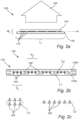
- Fig. 2a schematically shows a LED filament 100 according to an exemplifying embodiment of the present invention.
- the LED filament 100 which elongates along the axis, A, is configured to emit LED filament light 105.
- the LED filament light 105 emitted from the LED filament 100 during operation is preferably white light having a correlated color temperature, CCT, below 2500 K.
- the white light has preferably a color rendering index, CRI, of at least 80.
- the LED filament 100 may preferably have a length, L f , in the range from 1 cm to 20 cm, more preferably 2 cm to 12 cm, and most preferred 3 cm to 10 cm.
- the LED filament 100 may preferably have a width, W f , in the range from 0.5 mm to 10 mm, more preferably 0.8 mm to 8 mm, and most preferred 1 to 5 mm.
- the aspect ratio L f /W f is preferably at least 5, more preferably at least 8, and most preferred at least 10.
- the LED filament 100 comprises an array or "chain” of a plurality of LEDs 110 configured to emit LED light.
- the array or "chain" of the plurality of LEDs 110 may comprise a plurality of adjacently arranged LEDs 110.
- the plurality of LEDs 110 preferably comprises more than 5 LEDs, more preferably more than 8 LEDs, and even more preferred more than 10 LEDs.
- the LED filament 100 further comprises a carrier 130 arranged to support the plurality of LEDs 110.
- the plurality of LEDs 110 may be arranged, mounted and/or mechanically coupled on/to the carrier 130.
- the carrier 130 e.g. a substrate, is configured to mechanically and/or electrically support the plurality of LEDs 110.
- the carrier 130 may be a printed circuit board (PCB).
- the carrier 130 may be light transmissive and/or reflective.
- the carrier 130 may be flexible, and may for example comprise a polymer foil (e.g. polyimide (PI), polyethylene terephthalate (PET), etc.).
- the carrier 130 may comprise one or more thermally conductive layers and one or more insulating layers.
- the LED filament 110 further comprises an encapsulant 140.
- the encapsulant 140 comprises a translucent material.
- the encapsulant 140 comprises a luminescent material configured to at least partly convert light emitted from the plurality of LEDs 120 into converted light.
- the encapsulant 140 may comprise a light-scattering material configured to scatter light emitted from the plurality of LEDs 120.
- the light-scattering material may preferably have a reflectivity of > 70 %, more preferably > 80 %, and most preferably > 85 %.
- the encapsulant 140 may be flexible.
- the encapsulant 140 may comprise silicone.
- the encapsulant 140 via its luminescent material, may be configured to, during operation of the LED filament 100, convert a portion of the first LED light into first converted light at a first conversion ratio, R 1 , wherein the first converted light has a first converted light intensity, Iconv 1 (not shown) and convert a portion of the second LED light into second converted light at a second conversion ratio, R 1 , wherein the second converted light has a second converted light intensity, Iconv 2 (not shown) wherein R 1 /R 2 > 3 and 0.7 ⁇ (Iconv 1 /Iconv 2 ) ⁇ 1.3, preferably 0.8 ⁇ (Iconv 1 /Iconv 2 ) ⁇ 1.2.
- the encapsulant 140 at least partially encloses the plurality of LEDs 110 and the carrier 130.
- the encapsulant 140 fully encloses the plurality of LEDs 110.
- the encapsulant 140 partially encloses the carrier 130, as the length and/or width of the carrier 130 may be longer and/or wider than the length and/or width of the LED filament 110.
- the LED filament light 105 may hereby comprise the LED light and/or the converted light.
- the luminescent material of the encapsulant 140 is configured to emit light under external energy excitation.
- the luminescent material may comprise a fluorescent material.
- the luminescent material may comprise an inorganic phosphor, an organic phosphor and/or quantum dots/rods. More specifically, and according to an embodiment of the invention, the luminescent material of the encapsulant may comprises yttrium aluminium garnet (YAG), LuAg and/or LuYAG phosphor.
- YAG yttrium aluminium garnet
- LuAg LuAg
- LuYAG phosphor yttrium aluminium garnet
- the UV/blue LED light may be partially or fully absorbed by the luminescent material and converted to light of another color e.g. green, yellow, orange and/or red.
- Fig. 2b schematically shows the LED filament 100 of Fig. 2a according to an exemplifying embodiment of the present invention, and it is referred to Fig. 2a for an increased understanding of the features and/or operation of the LED filament 100.
- the plurality of LEDs 110 comprises a first set 150 of LEDs arranged to emit light in a first wavelength range of 430-490 nm. Hence, the first set 150 of LEDs is arranged to emit light which is predominantly blue.
- the plurality of LEDs 110 further comprises a second set 160 of LEDs arranged to emit light in a second wavelength range of 315-420 nm. Hence, the second set 150 of LEDs is arranged to emit light which is violet or ultraviolet (UV).
- UV violet or ultraviolet
- a number, N 1 , of the LEDs of the first set 150 of LEDs and a number, N 2 , of the LEDs of the second set 160 of LEDs, may, according to the example shown in Fig. 2b fulfill N 1 > 2 ⁇ N 2 , preferably N 1 > 3 ⁇ N 2 .
- the LED filament 100 further comprises circuitry 120 which is coupled to the plurality of LEDs 110.
- the circuitry 120 is configured to provide the first set of LEDs 150 with a first current, I c1 , during operation if the LED filament 100.
- the circuitry 120 is furthermore configured to provide the second set of LEDs 160 with a second current, I c2 , during operation of the LED filament 100.
- the LED filament 100 is configured to provide a larger current to the second set of LEDs 160, i.e. the violet LEDs, than to the first set of LEDs 150, i.e. the blue LEDs 150, such that I c2 > I c1 .
- the circuitry 120 may comprise a first circuit 120a coupled to the first set of LEDs 150 and a second circuit 120b coupled to the second set of LEDs 160.
- the first and second circuits 120a, 120b may be electrically isolated from each other.
- Fig. 2c schematically discloses portions of the circuitry 120 of the LED filament 100 of Fig. 2b , comprising the first set 150 of LEDs and the second set 160 of LEDs of the LED filament 100 of Fig. 2a and/or of Fig. 2b .
- the circuitry 120 of the LED filament 100 as exemplified in Fig. 2b is, via the example of Fig. 2c , arranged or configured such that two or more (blue) LEDs are coupled in parallel.
- the circuitry 120 of the LED filament 100 is arranged or configured such that two or more (violet) LEDs are coupled in series.
- the LED filament 100 may provide the first set 150 of LEDs with a first current, I c1 , and the second set 160 of LEDs with a second current, I c2 , during operation of the LED filament 100, wherein I c2 > I c1 .
- the circuitry 120 is configured to provide the first set 150 of LEDs with a first current per unit epitaxial area of p-n junction, I c1 , and to provide the second set 160 of LEDs with a second current, I c2 , per unit epitaxial of p-n junction, during operation of the LED filament, wherein I c2 > I c1 , so that the (second radiometric) power emitted per unit area by the second set 160 of LEDs is higher than the (first radiometric) power emitted per unit area for first set 150 of LEDs.
- Figs. 2a-c show exemplifying embodiments of LED filament(s) 110, and that the shape and/or number of LED filament(s) may differ from that/those shown.
- the LED filament(s) 100 may have a spiral, meander, coil and/or helix shape.
- Fig. 3a schematically discloses the relative intensity of the LED filament light during operation of a LED filament according to an example of the present invention.
- the luminescent material of the encapsulant of LED filament comprises an YAG Ce phosphor as a function of wavelength.
- Fig. 3a shows the excitation spectra 170 and the emission spectra 175 of the LED filament light, wherein arrow 180 indicates the distribution of the first (blue) LED light and arrow 190 indicates the wavelength of the second (violet) LED light.
- Fig. 3b schematically discloses the luminous flux, LF, as a function of intensity of the first and second LED light, respectively, in arbitrary units, of the LED filament light during operation of a LED filament according to an example of the present invention.
- the LED filament is arranged to emit LED filament light having a luminous flux, LF.
- the luminous flux, LF is above a first luminous flux threshold, LF t1 i.e.
- the first set of LEDs is arranged to emit first (blue) LED light with a first LED intensity, ILED 1
- the second set of LEDs is arranged to emit second (violet) LED light with a second LED intensity, ILED 2 , wherein ILED 1 ⁇ ILED 2 ⁇ 2 ⁇ ILED 1 , which is indicated in the right hand side of the diagram.
- the luminous flux, LF is below a second luminous flux threshold, LF t2 , i.e.
- the first set of LEDs is arranged to emit first (blue) LED light with a first LED intensity, ILED 1
- the second set of LEDs is arranged to emit second (violet) LED light with a second LED intensity, ILED 2 , wherein ILED 2 > 2 ⁇ ILED 1 , preferably ILED 2 > 3 ⁇ ILED 1 .
- the second (violet) LED intensity (light power per unit emitting area), ILED 2
- the second (violet) LED intensity is higher than the first (blue) LED intensity (light power per unit emitting area), ILED 1 , and may almost be as high as two times the first (blue) LED intensity, ILED 1 .
- the second (violet) LED intensity, ILED 2 may be significantly higher than the first (blue) LED intensity, ILED 1 , as it may be more than three times as high as the first (blue) LED intensity, ILED 1 .
- the first luminous flux threshold, LF t1 and the second luminous flux threshold, LF t2 may have the same value, or alternatively, have different values.
- Fig. 4 schematically shows a LED filament arrangement 200 according to an embodiment of the present invention.
- the LED filament arrangement 200 comprises at least one LED filament 100 according to any one of the preceding embodiments. It should be noted that it is referred to Figs. 2a-2c for an increased understanding of features and/or functions of the LED filament 100.
- the LED filament arrangement 200 further comprises a controller 210 coupled to the circuitry of the LED filament 100, wherein the controller 210 is configured to individually control the operation of the first set of LEDs and the second set of LEDs of the LED filament 100.
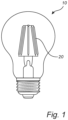
- Fig. 5 schematically shows a LED lighting device 500 according to an embodiment of the present invention.
- the LED lighting device 500 which may constitute a lamp or a luminaire, comprises one or more LED filaments 110 according to any one of the previously described embodiments.
- the LED lighting device 500 further comprises a cover 510, which is exemplified as being bulb-shaped.
- the cover 510 may comprise an at least partially light transmissive (e.g. transparent) material, and the cover 510 at least partially encloses the LED filament 100.
- the LED lighting device 500 further comprises an electrical connection 520 connected to the LED filament 100 for a supply of power to the plurality of LEDs of the LED filament 100.
- Fig. 6 schematically shows radiometric power of UV/violet LEDs/radiometric power of LEDs emitting at 450 nm for obtaining the same lumen output for the first and second set of LEDs through the phosphor of the encapsulant according to an embodiment of the present invention.
- one or more of the LED filament 100, the carrier 130, the encapsulant 140, etc. may have different shapes, dimensions and/or sizes than those depicted/described.
Landscapes
- Engineering & Computer Science (AREA)
- Physics & Mathematics (AREA)
- Microelectronics & Electronic Packaging (AREA)
- Optics & Photonics (AREA)
- General Engineering & Computer Science (AREA)
- Non-Portable Lighting Devices Or Systems Thereof (AREA)
Claims (14)
- Filament à diode électroluminescente, DEL, (100) configuré pour émettre une lumière de filament à DEL (105), comprenantun réseau d'une pluralité de diodes électroluminescentes (110), DEL, configurées pour émettre une lumière DEL,une circuiterie (120) couplée à la pluralité de DEL,un support (130) conçu pour soutenir la pluralité de DEL,un agent d'encapsulation (140) comprenant un matériau translucide et un matériau luminescent configuré pour convertir au moins partiellement la lumière DEL en lumière convertie, dans lequel l'agent d'encapsulation entoure au moins partiellement la pluralité de DEL et le support,dans lequel la pluralité de DEL comprend un premier ensemble (150) de DEL conçues pour émettre une première lumière DEL dans une première gamme de longueurs d'onde de 430 à 490 nm, et un second ensemble (160) de DEL conçues pour émettre une seconde lumière DEL dans une seconde gamme de longueurs d'onde de 315 à 420 nm,dans lequel la circuiterie est configurée pour fournir, au premier ensemble de DEL, un premier courant, Ic1, et pour fournir, au second ensemble de DEL, un second courant, Ic2, pendant le fonctionnement du filament à DEL, dans lequel Ic2 > Ic1 etdans lequel l'agent d'encapsulation, par l'intermédiaire de son matériau luminescent, est configuré pour, pendant le fonctionnement du filament à DEL,convertir une partie de la première lumière DEL en première lumière convertie à un premier rapport de conversion, R1, dans lequel la première lumière convertie a une première intensité lumineuse convertie, Iconv1, et convertir une partie de la seconde lumière DEL en seconde lumière convertie à un second rapport de conversion, R2, dans lequel la seconde lumière convertie a une seconde intensité lumineuse convertie, Iconv2,où R1/R2 > 3 et 0,7 < (Iconv1/Iconv2) < 1,3, de préférence 0,8 < (Iconv1/Iconv2) < 1,2.
- Filament à DEL selon la revendication 1, dans lequel le premier courant, Ic1, et le second courant, Ic2, satisfont Ic2 > 3·Ic1.
- Filament à DEL selon la revendication 1 ou 2, dans lequel au moins deux DEL du premier ensemble de DEL sont couplées en parallèle, et dans lequel au moins deux DEL du second ensemble de DEL sont couplées en série.
- Filament à DEL selon l'une quelconque des revendications précédentes, dans lequel la circuiterie comprend un premier circuit (120a) couplé au premier ensemble de DEL et un second circuit (120b) couplé au second ensemble de DEL, dans lequel le premier et le second circuit sont électriquement isolés l'un de l'autre.
- Filament à DEL selon l'une quelconque des revendications précédentes, dans lequel le premier ensemble de DEL est conçu pour émettre la première lumière DEL avec une première intensité DEL, ILED1, et dans lequel le second ensemble de DEL est conçu pour émettre la seconde lumière DEL avec une seconde intensité DEL, ILED2, où ILED2 > 2·ILED1.
- Filament à DEL selon l'une quelconque des revendications 1 à 4, dans lequel le filament à DEL est conçu pour émettre une lumière de filament à DEL ayant un flux lumineux, LF, dans lequelsi le flux lumineux, LF, est supérieur à un premier seuil de flux lumineux, LFt1,le premier ensemble de DEL est conçu pour émettre une première lumière de DEL avec une première intensité de DEL, ILED1, et le second ensemble de DEL est conçu pour émettre une seconde lumière de DEL avec une seconde intensité de DEL, ILED2, où ILED1 ≤ ILED2 < 2·ILED1, etsi le flux lumineux, LF, est inférieur à un second seuil de flux lumineux, LFt2,le premier ensemble de DEL est conçu pour émettre une première lumière de DEL avec une première intensité de DEL, ILED1, et le second ensemble de DEL est conçu pour émettre une seconde lumière de DEL avec une seconde intensité de DEL, ILED2, où ILED2 > 8·ILED1.
- Filament à DEL selon l'une quelconque des revendications précédentes, dans lequel le second ensemble de DEL est conçu pour émettre une seconde lumière DEL dans une seconde sous-gamme de longueurs d'onde de 400 à 420 nm, dans lequel une première intensité lumineuse de la première lumière DEL, LIb, et une seconde intensité lumineuse de la seconde lumière DEL, LIv, satisfont 1,2·LIb > LIv > 0,8·LIb.
- Filament à DEL selon l'une quelconque des revendications précédentes, dans lequel un nombre, N1, de DEL du premier ensemble de DEL et un nombre, N2, de DEL du second ensemble de DEL satisfont N1 > 2·N2.
- Filament à DEL selon l'une quelconque des revendications précédentes, dans lequel le matériau luminescent de l'agent d'encapsulation comprend au moins l'un parmi un phosphore YAG, LuAg et LuYAG.
- Filament à DEL selon l'une quelconque des revendications précédentes, dans lequel le filament à DEL a au moins l'une parmi une forme de spirale, en dents de scie, de bobine et d'hélice.
- Filament à DEL selon l'une quelconque des revendications précédentes, dans lequel la lumière de filament à DEL est une lumière blanche ayant une température de couleur proximale, CCT, inférieure à 2 500 K.
- Agencement de filaments à DEL (200) comprenant :au moins un filament à DEL selon l'une quelconque des revendications précédentes, etun dispositif de commande (210) couplé à la circuiterie, dans lequel le dispositif de commande est configuré pour commander individuellement le fonctionnement du premier ensemble de DEL et du second ensemble de DEL.
- Agencement de filaments à DEL selon la revendication 12, dans lequel le dispositif de commande est configuré pour commander individuellement le fonctionnement du premier ensemble de DEL et du second ensemble de DEL par au moins l'une parmil'augmentation d'une première intensité, ILED1 du premier ensemble de DEL, etl'augmentation d'une seconde intensité, ILED2, du second ensemble de DEL de telle sorte que 0 ≤ ILED1 ≤ 0,5·ILED2, etla diminution d'une première intensité, ILED1, du premier ensemble de DEL, etla diminution d'une seconde intensité, ILED2, du second ensemble de DEL de telle sorte que 0 ≤ ILED1 ≤ 0,5·ILED2.
- Dispositif d'éclairage à DEL (500) comprenant l'un parmi- un filament à DEL selon l'une quelconque des revendications 1 à 11, dans lequel le dispositif d'éclairage à DEL comprend en outre un couvercle (510) constitué d'un matériau au moins partiellement transparent, dans lequel le couvercle entoure au moins partiellement le filament à DEL, et une connexion électrique (520) connectée au filament à DEL pour l'alimentation de la pluralité de DEL du filament à DEL, et- un agencement de filaments à DEL selon la revendication 12 ou 13, dans lequel le dispositif d'éclairage à DEL comprend en outre un couvercle (510) constitué d'un matériau au moins partiellement transparent, dans lequel le couvercle entoure au moins partiellement le filament à DEL, et une connexion électrique (520) connectée au filament à DEL pour l'alimentation de la pluralité de DEL du filament à DEL.
Applications Claiming Priority (2)
| Application Number | Priority Date | Filing Date | Title |
|---|---|---|---|
| EP22150644 | 2022-01-10 | ||
| PCT/EP2022/087679 WO2023131551A1 (fr) | 2022-01-10 | 2022-12-23 | Filament à del pour éclairage et désinfection |
Publications (2)
| Publication Number | Publication Date |
|---|---|
| EP4464128A1 EP4464128A1 (fr) | 2024-11-20 |
| EP4464128B1 true EP4464128B1 (fr) | 2025-06-25 |
Family
ID=79287959
Family Applications (1)
| Application Number | Title | Priority Date | Filing Date |
|---|---|---|---|
| EP22838885.6A Active EP4464128B1 (fr) | 2022-01-10 | 2022-12-23 | Filament à del pour éclairage et désinfection |
Country Status (4)
| Country | Link |
|---|---|
| US (1) | US12398849B2 (fr) |
| EP (1) | EP4464128B1 (fr) |
| CN (1) | CN118525604B (fr) |
| WO (1) | WO2023131551A1 (fr) |
Family Cites Families (15)
| Publication number | Priority date | Publication date | Assignee | Title |
|---|---|---|---|---|
| US5712468A (en) * | 1995-06-01 | 1998-01-27 | Ace; Ronald | Microwave oven illumination |
| US7358679B2 (en) * | 2002-05-09 | 2008-04-15 | Philips Solid-State Lighting Solutions, Inc. | Dimmable LED-based MR16 lighting apparatus and methods |
| US20080008620A1 (en) * | 2006-06-23 | 2008-01-10 | Alkis Alexiadis | Bimodal light bulb and devices for sterilizing and cleansing |
| CN201028461Y (zh) | 2007-05-24 | 2008-02-27 | 河源市粤兴实业有限公司 | 一种家用灭虫照明灯 |
| EP3011804B1 (fr) * | 2013-06-20 | 2017-10-18 | Philips Lighting Holding B.V. | Dispositif d'éclairage comprenant au moins deux ensembles de diodes électroluminescentes |
| JP6256699B2 (ja) | 2014-11-11 | 2018-01-10 | 豊田合成株式会社 | 発光装置 |
| US20170014538A1 (en) * | 2015-07-14 | 2017-01-19 | Juha Rantala | LED structure and luminaire for continuous disinfection |
| WO2017200097A1 (fr) | 2016-05-20 | 2017-11-23 | 株式会社 東芝 | Source de lumière blanche |
| CN110402494A (zh) * | 2017-01-13 | 2019-11-01 | 尤哈·兰塔拉 | 用于持续消毒的led结构和照明器 |
| US10887960B2 (en) | 2019-03-28 | 2021-01-05 | Lumileds Llc | Color tunable light emitting diode (LED) systems, LED lighting systems, and methods |
| WO2020239655A1 (fr) | 2019-05-29 | 2020-12-03 | Signify Holding B.V. | Dispositif d'éclairage comprenant un filament électroluminescent |
| CN112300777B (zh) | 2019-07-26 | 2022-01-18 | 纳晶科技股份有限公司 | 一种核壳量子点及其制备方法、量子点光电器件 |
| PL4004432T3 (pl) * | 2019-07-26 | 2023-04-17 | Signify Holding B.V. | Układ włókien diod elektroluminescencyjnych |
| US11460171B1 (en) * | 2021-12-03 | 2022-10-04 | Volt, LLC | Selectively-adjustable beam angle lamp |
| CN219082831U (zh) * | 2022-12-29 | 2023-05-26 | 深圳市冠科科技有限公司 | 球泡灯 |
-
2022
- 2022-12-23 EP EP22838885.6A patent/EP4464128B1/fr active Active
- 2022-12-23 US US18/727,722 patent/US12398849B2/en active Active
- 2022-12-23 CN CN202280088175.5A patent/CN118525604B/zh active Active
- 2022-12-23 WO PCT/EP2022/087679 patent/WO2023131551A1/fr not_active Ceased
Also Published As
| Publication number | Publication date |
|---|---|
| US12398849B2 (en) | 2025-08-26 |
| US20250146628A1 (en) | 2025-05-08 |
| WO2023131551A1 (fr) | 2023-07-13 |
| EP4464128A1 (fr) | 2024-11-20 |
| CN118525604A (zh) | 2024-08-20 |
| CN118525604B (zh) | 2025-11-18 |
Similar Documents
| Publication | Publication Date | Title |
|---|---|---|
| EP3987218B1 (fr) | Dispositif d'éclairage à température de couleur commandable comprenant différents filaments à del | |
| EP4038311B1 (fr) | Agencement de filament à del | |
| CN114641646B (zh) | 包括三个类型的led的发光二极管灯丝 | |
| US11913608B2 (en) | LED filament arrangement | |
| CN113330245B (zh) | Led灯丝装置 | |
| EP4004432B1 (fr) | Agencement de filament à del | |
| EP4464128B1 (fr) | Filament à del pour éclairage et désinfection | |
| EP4532972B1 (fr) | Agencement de filament de source lumineuse à del comprenant des del bleues et rouges | |
| EP4646549A1 (fr) | Filament à del comprenant des del agencées pour émettre une lumière infrarouge proche | |
| WO2020229462A1 (fr) | Agencement de filament à del | |
| EP4666002A1 (fr) | Agencement de filament à del | |
| WO2026017508A1 (fr) | Filament de del | |
| WO2025252448A1 (fr) | Filament de del comprenant un agencement de filament de del | |
| WO2024188830A1 (fr) | Lampe à filament à del | |
| WO2024146806A1 (fr) | Agencement de filament à del comprenant des del agencées pour émettre une lumière proche infrarouge |
Legal Events
| Date | Code | Title | Description |
|---|---|---|---|
| STAA | Information on the status of an ep patent application or granted ep patent |
Free format text: STATUS: UNKNOWN |
|
| STAA | Information on the status of an ep patent application or granted ep patent |
Free format text: STATUS: THE INTERNATIONAL PUBLICATION HAS BEEN MADE |
|
| PUAI | Public reference made under article 153(3) epc to a published international application that has entered the european phase |
Free format text: ORIGINAL CODE: 0009012 |
|
| STAA | Information on the status of an ep patent application or granted ep patent |
Free format text: STATUS: REQUEST FOR EXAMINATION WAS MADE |
|
| 17P | Request for examination filed |
Effective date: 20240812 |
|
| AK | Designated contracting states |
Kind code of ref document: A1 Designated state(s): AL AT BE BG CH CY CZ DE DK EE ES FI FR GB GR HR HU IE IS IT LI LT LU LV MC ME MK MT NL NO PL PT RO RS SE SI SK SM TR |
|
| GRAP | Despatch of communication of intention to grant a patent |
Free format text: ORIGINAL CODE: EPIDOSNIGR1 |
|
| RIC1 | Information provided on ipc code assigned before grant |
Ipc: F21Y 113/17 20160101ALI20241226BHEP Ipc: F21K 9/232 20160101ALI20241226BHEP Ipc: H05B 45/10 20200101AFI20241226BHEP |
|
| STAA | Information on the status of an ep patent application or granted ep patent |
Free format text: STATUS: GRANT OF PATENT IS INTENDED |
|
| DAV | Request for validation of the european patent (deleted) | ||
| DAX | Request for extension of the european patent (deleted) | ||
| INTG | Intention to grant announced |
Effective date: 20250130 |
|
| GRAS | Grant fee paid |
Free format text: ORIGINAL CODE: EPIDOSNIGR3 |
|
| P01 | Opt-out of the competence of the unified patent court (upc) registered |
Free format text: CASE NUMBER: APP_18349/2025 Effective date: 20250415 |
|
| GRAA | (expected) grant |
Free format text: ORIGINAL CODE: 0009210 |
|
| STAA | Information on the status of an ep patent application or granted ep patent |
Free format text: STATUS: THE PATENT HAS BEEN GRANTED |
|
| AK | Designated contracting states |
Kind code of ref document: B1 Designated state(s): AL AT BE BG CH CY CZ DE DK EE ES FI FR GB GR HR HU IE IS IT LI LT LU LV MC ME MK MT NL NO PL PT RO RS SE SI SK SM TR |
|
| REG | Reference to a national code |
Ref country code: GB Ref legal event code: FG4D |
|
| REG | Reference to a national code |
Ref country code: CH Ref legal event code: EP |
|
| REG | Reference to a national code |
Ref country code: DE Ref legal event code: R096 Ref document number: 602022016613 Country of ref document: DE |
|
| REG | Reference to a national code |
Ref country code: CH Ref legal event code: EP |
|
| REG | Reference to a national code |
Ref country code: IE Ref legal event code: FG4D |
|
| PG25 | Lapsed in a contracting state [announced via postgrant information from national office to epo] |
Ref country code: FI Free format text: LAPSE BECAUSE OF FAILURE TO SUBMIT A TRANSLATION OF THE DESCRIPTION OR TO PAY THE FEE WITHIN THE PRESCRIBED TIME-LIMIT Effective date: 20250625 |
|
| REG | Reference to a national code |
Ref country code: LT Ref legal event code: MG9D |
|
| PG25 | Lapsed in a contracting state [announced via postgrant information from national office to epo] |
Ref country code: GR Free format text: LAPSE BECAUSE OF FAILURE TO SUBMIT A TRANSLATION OF THE DESCRIPTION OR TO PAY THE FEE WITHIN THE PRESCRIBED TIME-LIMIT Effective date: 20250926 Ref country code: NO Free format text: LAPSE BECAUSE OF FAILURE TO SUBMIT A TRANSLATION OF THE DESCRIPTION OR TO PAY THE FEE WITHIN THE PRESCRIBED TIME-LIMIT Effective date: 20250925 |
|
| PG25 | Lapsed in a contracting state [announced via postgrant information from national office to epo] |
Ref country code: BG Free format text: LAPSE BECAUSE OF FAILURE TO SUBMIT A TRANSLATION OF THE DESCRIPTION OR TO PAY THE FEE WITHIN THE PRESCRIBED TIME-LIMIT Effective date: 20250625 |
|
| PG25 | Lapsed in a contracting state [announced via postgrant information from national office to epo] |
Ref country code: HR Free format text: LAPSE BECAUSE OF FAILURE TO SUBMIT A TRANSLATION OF THE DESCRIPTION OR TO PAY THE FEE WITHIN THE PRESCRIBED TIME-LIMIT Effective date: 20250625 |
|
| PG25 | Lapsed in a contracting state [announced via postgrant information from national office to epo] |
Ref country code: RS Free format text: LAPSE BECAUSE OF FAILURE TO SUBMIT A TRANSLATION OF THE DESCRIPTION OR TO PAY THE FEE WITHIN THE PRESCRIBED TIME-LIMIT Effective date: 20250925 |
|
| PG25 | Lapsed in a contracting state [announced via postgrant information from national office to epo] |
Ref country code: LV Free format text: LAPSE BECAUSE OF FAILURE TO SUBMIT A TRANSLATION OF THE DESCRIPTION OR TO PAY THE FEE WITHIN THE PRESCRIBED TIME-LIMIT Effective date: 20250625 |
|
| REG | Reference to a national code |
Ref country code: NL Ref legal event code: MP Effective date: 20250625 |
|
| PG25 | Lapsed in a contracting state [announced via postgrant information from national office to epo] |
Ref country code: NL Free format text: LAPSE BECAUSE OF FAILURE TO SUBMIT A TRANSLATION OF THE DESCRIPTION OR TO PAY THE FEE WITHIN THE PRESCRIBED TIME-LIMIT Effective date: 20250625 |
|
| PG25 | Lapsed in a contracting state [announced via postgrant information from national office to epo] |
Ref country code: PT Free format text: LAPSE BECAUSE OF FAILURE TO SUBMIT A TRANSLATION OF THE DESCRIPTION OR TO PAY THE FEE WITHIN THE PRESCRIBED TIME-LIMIT Effective date: 20251027 |
|
| REG | Reference to a national code |
Ref country code: AT Ref legal event code: MK05 Ref document number: 1808044 Country of ref document: AT Kind code of ref document: T Effective date: 20250625 |
|
| PG25 | Lapsed in a contracting state [announced via postgrant information from national office to epo] |
Ref country code: IS Free format text: LAPSE BECAUSE OF FAILURE TO SUBMIT A TRANSLATION OF THE DESCRIPTION OR TO PAY THE FEE WITHIN THE PRESCRIBED TIME-LIMIT Effective date: 20251025 |
|
| PG25 | Lapsed in a contracting state [announced via postgrant information from national office to epo] |
Ref country code: SM Free format text: LAPSE BECAUSE OF FAILURE TO SUBMIT A TRANSLATION OF THE DESCRIPTION OR TO PAY THE FEE WITHIN THE PRESCRIBED TIME-LIMIT Effective date: 20250625 Ref country code: AT Free format text: LAPSE BECAUSE OF FAILURE TO SUBMIT A TRANSLATION OF THE DESCRIPTION OR TO PAY THE FEE WITHIN THE PRESCRIBED TIME-LIMIT Effective date: 20250625 |
|
| PGFP | Annual fee paid to national office [announced via postgrant information from national office to epo] |
Ref country code: FR Payment date: 20251230 Year of fee payment: 4 |
|
| PG25 | Lapsed in a contracting state [announced via postgrant information from national office to epo] |
Ref country code: CZ Free format text: LAPSE BECAUSE OF FAILURE TO SUBMIT A TRANSLATION OF THE DESCRIPTION OR TO PAY THE FEE WITHIN THE PRESCRIBED TIME-LIMIT Effective date: 20250625 |
|
| PG25 | Lapsed in a contracting state [announced via postgrant information from national office to epo] |
Ref country code: PL Free format text: LAPSE BECAUSE OF FAILURE TO SUBMIT A TRANSLATION OF THE DESCRIPTION OR TO PAY THE FEE WITHIN THE PRESCRIBED TIME-LIMIT Effective date: 20250625 |
|
| PG25 | Lapsed in a contracting state [announced via postgrant information from national office to epo] |
Ref country code: EE Free format text: LAPSE BECAUSE OF FAILURE TO SUBMIT A TRANSLATION OF THE DESCRIPTION OR TO PAY THE FEE WITHIN THE PRESCRIBED TIME-LIMIT Effective date: 20250625 |
|
| PG25 | Lapsed in a contracting state [announced via postgrant information from national office to epo] |
Ref country code: SK Free format text: LAPSE BECAUSE OF FAILURE TO SUBMIT A TRANSLATION OF THE DESCRIPTION OR TO PAY THE FEE WITHIN THE PRESCRIBED TIME-LIMIT Effective date: 20250625 |
|
| PG25 | Lapsed in a contracting state [announced via postgrant information from national office to epo] |
Ref country code: ES Free format text: LAPSE BECAUSE OF FAILURE TO SUBMIT A TRANSLATION OF THE DESCRIPTION OR TO PAY THE FEE WITHIN THE PRESCRIBED TIME-LIMIT Effective date: 20250625 |
|
| PG25 | Lapsed in a contracting state [announced via postgrant information from national office to epo] |
Ref country code: RO Free format text: LAPSE BECAUSE OF FAILURE TO SUBMIT A TRANSLATION OF THE DESCRIPTION OR TO PAY THE FEE WITHIN THE PRESCRIBED TIME-LIMIT Effective date: 20250625 |
|
| PG25 | Lapsed in a contracting state [announced via postgrant information from national office to epo] |
Ref country code: DK Free format text: LAPSE BECAUSE OF FAILURE TO SUBMIT A TRANSLATION OF THE DESCRIPTION OR TO PAY THE FEE WITHIN THE PRESCRIBED TIME-LIMIT Effective date: 20250625 |
|
| PGFP | Annual fee paid to national office [announced via postgrant information from national office to epo] |
Ref country code: DE Payment date: 20260220 Year of fee payment: 4 |
|
| PG25 | Lapsed in a contracting state [announced via postgrant information from national office to epo] |
Ref country code: IT Free format text: LAPSE BECAUSE OF FAILURE TO SUBMIT A TRANSLATION OF THE DESCRIPTION OR TO PAY THE FEE WITHIN THE PRESCRIBED TIME-LIMIT Effective date: 20250625 |