EP4464178A1 - Aerosolerzeugungsvorrichtung, steuerungsverfahren dafür, steuerungsvorrichtung und speichermedium - Google Patents
Aerosolerzeugungsvorrichtung, steuerungsverfahren dafür, steuerungsvorrichtung und speichermedium Download PDFInfo
- Publication number
- EP4464178A1 EP4464178A1 EP22919991.4A EP22919991A EP4464178A1 EP 4464178 A1 EP4464178 A1 EP 4464178A1 EP 22919991 A EP22919991 A EP 22919991A EP 4464178 A1 EP4464178 A1 EP 4464178A1
- Authority
- EP
- European Patent Office
- Prior art keywords
- heating element
- inhalation
- aerosol
- generation device
- voltage value
- Prior art date
- Legal status (The legal status is an assumption and is not a legal conclusion. Google has not performed a legal analysis and makes no representation as to the accuracy of the status listed.)
- Pending
Links
- 239000000443 aerosol Substances 0.000 title claims abstract description 117
- 238000000034 method Methods 0.000 title claims abstract description 26
- 238000001514 detection method Methods 0.000 claims abstract description 140
- 238000010438 heat treatment Methods 0.000 claims abstract description 130
- 230000009471 action Effects 0.000 claims abstract description 69
- 239000000758 substrate Substances 0.000 claims abstract description 19
- 238000004590 computer program Methods 0.000 claims description 19
- 238000000889 atomisation Methods 0.000 claims description 13
- 230000008859 change Effects 0.000 description 7
- 230000007423 decrease Effects 0.000 description 6
- 238000010586 diagram Methods 0.000 description 6
- 238000005516 engineering process Methods 0.000 description 5
- 239000007788 liquid Substances 0.000 description 3
- 230000008569 process Effects 0.000 description 3
- 230000000712 assembly Effects 0.000 description 2
- 238000000429 assembly Methods 0.000 description 2
- 238000013461 design Methods 0.000 description 2
- 230000006870 function Effects 0.000 description 2
- 239000007787 solid Substances 0.000 description 2
- 230000002159 abnormal effect Effects 0.000 description 1
- 230000005856 abnormality Effects 0.000 description 1
- 230000005540 biological transmission Effects 0.000 description 1
- 238000004364 calculation method Methods 0.000 description 1
- 238000004891 communication Methods 0.000 description 1
- 238000011161 development Methods 0.000 description 1
- 239000003571 electronic cigarette Substances 0.000 description 1
- 239000000463 material Substances 0.000 description 1
- 229910044991 metal oxide Inorganic materials 0.000 description 1
- 150000004706 metal oxides Chemical class 0.000 description 1
- 238000012986 modification Methods 0.000 description 1
- 230000004048 modification Effects 0.000 description 1
- 230000003287 optical effect Effects 0.000 description 1
- 239000004065 semiconductor Substances 0.000 description 1
- 230000000087 stabilizing effect Effects 0.000 description 1
- 230000003068 static effect Effects 0.000 description 1
- 230000001960 triggered effect Effects 0.000 description 1
Images

Classifications
-
- A—HUMAN NECESSITIES
- A24—TOBACCO; CIGARS; CIGARETTES; SIMULATED SMOKING DEVICES; SMOKERS' REQUISITES
- A24F—SMOKERS' REQUISITES; MATCH BOXES; SIMULATED SMOKING DEVICES
- A24F40/00—Electrically operated smoking devices; Component parts thereof; Manufacture thereof; Maintenance or testing thereof; Charging means specially adapted therefor
- A24F40/50—Control or monitoring
-
- A—HUMAN NECESSITIES
- A24—TOBACCO; CIGARS; CIGARETTES; SIMULATED SMOKING DEVICES; SMOKERS' REQUISITES
- A24F—SMOKERS' REQUISITES; MATCH BOXES; SIMULATED SMOKING DEVICES
- A24F40/00—Electrically operated smoking devices; Component parts thereof; Manufacture thereof; Maintenance or testing thereof; Charging means specially adapted therefor
- A24F40/40—Constructional details, e.g. connection of cartridges and battery parts
-
- A—HUMAN NECESSITIES
- A24—TOBACCO; CIGARS; CIGARETTES; SIMULATED SMOKING DEVICES; SMOKERS' REQUISITES
- A24F—SMOKERS' REQUISITES; MATCH BOXES; SIMULATED SMOKING DEVICES
- A24F40/00—Electrically operated smoking devices; Component parts thereof; Manufacture thereof; Maintenance or testing thereof; Charging means specially adapted therefor
- A24F40/40—Constructional details, e.g. connection of cartridges and battery parts
- A24F40/46—Shape or structure of electric heating means
-
- A—HUMAN NECESSITIES
- A24—TOBACCO; CIGARS; CIGARETTES; SIMULATED SMOKING DEVICES; SMOKERS' REQUISITES
- A24F—SMOKERS' REQUISITES; MATCH BOXES; SIMULATED SMOKING DEVICES
- A24F40/00—Electrically operated smoking devices; Component parts thereof; Manufacture thereof; Maintenance or testing thereof; Charging means specially adapted therefor
- A24F40/50—Control or monitoring
- A24F40/51—Arrangement of sensors
-
- A—HUMAN NECESSITIES
- A24—TOBACCO; CIGARS; CIGARETTES; SIMULATED SMOKING DEVICES; SMOKERS' REQUISITES
- A24F—SMOKERS' REQUISITES; MATCH BOXES; SIMULATED SMOKING DEVICES
- A24F40/00—Electrically operated smoking devices; Component parts thereof; Manufacture thereof; Maintenance or testing thereof; Charging means specially adapted therefor
- A24F40/50—Control or monitoring
- A24F40/53—Monitoring, e.g. fault detection
-
- A—HUMAN NECESSITIES
- A24—TOBACCO; CIGARS; CIGARETTES; SIMULATED SMOKING DEVICES; SMOKERS' REQUISITES
- A24F—SMOKERS' REQUISITES; MATCH BOXES; SIMULATED SMOKING DEVICES
- A24F40/00—Electrically operated smoking devices; Component parts thereof; Manufacture thereof; Maintenance or testing thereof; Charging means specially adapted therefor
- A24F40/50—Control or monitoring
- A24F40/57—Temperature control
Definitions
- the present invention relates to the field of atomization technology, and particularly to an aerosol generation device, a control method and a control apparatus thereof, and a storage medium.
- aerosol atomization technology achieves the atomization by heating an aerosol-forming substrate via a heating element to generate the aerosol.
- a user inhales the aerosol generated by the aerosol generation device through an inhalation action.
- Some aerosol generation devices used for inhalation are provided with a function of recording the number of times of inhalation, which can be used for analyzing usage habits, determining the remaining amount of the aerosol-forming substrate, etc.
- a sensor is generally used for detecting whether the user performs an inhalation action by detecting the airflow, and counts are performed based on the detection results, but a special sensor needs to be provided to detect the inhalation action.
- An aerosol generation device for supplying an aerosol for inhalation by a user when the user inhales the aerosol through the aerosol generation device, the device includes:
- the detection assembly is connected between the heating element and the power supply and is configured to divide a voltage value with the heating element, the detection assembly includes a reference resistor and a detection switch;
- control assembly is configured to calculate an inhalation state quantity according to the first voltage value and the second voltage value, and determine that an inhalation action occurs at a current moment when an absolute value of a difference between the inhalation state quantity at the current moment and an inhalation state quantity at a previous moment is greater than a preset threshold value.
- the inhalation state quantity is equal to a difference value between the first voltage value and the second voltage value multiplied by the second voltage value.
- control assembly is further configured to update a record of the number of times of inhalation when determining that the inhalation action occurs.
- the aerosol generation device further includes:
- a control method for an aerosol generation device is provided, the aerosol generation device is configured to provide an aerosol for inhalation by a user when the user inhales the aerosol through the aerosol generation device, the aerosol generation device includes a heating element, a power supply and a detection assembly, the heating element is configured to heat an aerosol-forming substrate to generate the aerosol, the detection assembly is electrically connected to the heating element and the power supply; the control method includes:
- the detection assembly is connected between the heating element and the power supply, and includes a reference resistor and a detection switch, a first terminal of the reference resistor is electrically connected to the power supply via the detection switch, and a second terminal of the reference resistor is electrically connected to the heating element, the electrical parameter of the detection assembly includes a first voltage value at the first terminal and a second voltage value at the second terminal of the reference resistor; determining the inhalation action of the user according to changes in voltage values at both terminals of the detection assembly includes:
- the inhalation state quantity is equal to a difference value between the first voltage value and the second voltage value multiplied by the second voltage value.
- control method further includes: updating a record of the number of times of inhalation when determining that the inhalation action occurs.
- a control apparatus for an aerosol generation device is provided, the aerosol generation device is configured to provide the aerosol for inhalation by a user when the user inhales the aerosol through the aerosol generation device, the aerosol generation device includes a heating element, a power supply and a detection assembly, the heating element is configured to heat an aerosol-forming substrate to generate the aerosol, the detection assembly is electrically connected to the heating element and the power supply; the control apparatus includes:
- An aerosol generation device for supplying an aerosol for inhalation by a user when the user inhales the aerosol through the aerosol generation device, the aerosol generation device includes:
- a computer-readable storage medium on which a computer program is stored.
- the computer program when executed by a processor, causes the processor to implement the steps of:
- the detection assembly is electrically connected to the power supply and the heating element.
- the resistance value may also increase, thereby causing the electrical parameter of the detection assembly electrically connected to the heating element to change.
- the heating duration increases, the heating temperature of the heating element tends to be stable, and the resistance value of the heating element also tends to be stable.
- the heat of the heating element may decrease, causing the resistance value of the heating element to decrease. Therefore, it can be determined whether the user performs the inhalation action according to the electrical parameter of the detection assembly, thereby accurately detecting the inhalation action to implement accurate counting of the number of times of inhalation, and the cost is lower.
- first, second, etc. used in the present application can be used for describing various technical features, but these technical features are not limited by these terms. These terms are merely used for distinguishing a first feature from another assembly feature.
- connection in the following embodiments should be understood as “electrical connection”, “communication connection”, etc., if there is transmission of electrical signals or data between the connected objects.
- an aerosol generation device is provided, and the aerosol generation device is configured to provide an aerosol for inhalation by a user when the user inhales the aerosol through the aerosol generation device.
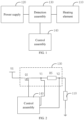
- the aerosol generation device includes a heating element 110, a power supply 120, a detection assembly 130, and a control assembly 140.
- the heating element 110 is configured to heat the aerosol-forming substrate to generate the aerosol.
- the power supply 120 is electrically connected to the heating element 110, and is configured to supply electric energy to the heating element 110 to allow the heating element 110 to generate heat.
- the detection assembly 130 is electrically connected to the heating element 110 and the power supply 120.
- the control assembly 140 is electrically connected to the detection assembly 130 and is configured to acquire an electrical parameter of the detection assembly 130, and identify an inhalation action of the user according to the electrical parameter of the detection assembly 130.
- the detection assembly 130 is electrically connected to the power supply 120 and the heating element 110.
- a resistance value thereof may also increase, thereby causing the electrical parameter of the detection assembly 130 electrically connected to the heating element to change.
- the heating duration of the heating element 110 increases, the heating temperature tends to be stable, and thus the resistance value of the heating element 110 also tends to be stable.
- the heat of the heating element 110 may decrease, which also causes the decrease of the resistance value of the heating element 110. Accordingly, it is possible to determine whether the user performs the inhalation according to the electrical parameter of the detection assembly, so that the inhalation action can be accurately detected.
- the electrical parameter of the detection assembly 130 may be the resistance value, a voltage value across both terminals of the detection assembly 30, a power, a current, etc.
- the voltage value across both terminals of the detection assembly 130 is taken as an example for illustration.
- control assembly 140 may control the heating temperature of the heating element 110 by controlling the power outputted by the power supply 120 to the heating element 110 or a duration of continuous output, so that the heating element 110 is maintained at a temperature for stabilizing the atomization or generating the aerosol.
- the power supply 120 also has another connection path with the heating element 110, and when no detection is required, the power supply 120 supplies power to the heating assembly through this path.
- the resistance value of the heating element 110 may change with the temperature. When the temperature rises, the resistance value of the heating element 110 also increases.
- the control assembly 140 can keep the resistance value of the detection assembly 130 unchanged by limiting a power-on duration of the detection assembly 130. Based on the voltage value division principle, the temperature change of the heating element 110 can be reflected by detecting the voltage value changes at both terminals of the assembly 130. When the temperature suddenly changes, it can be determined that the user performs an inhalation action on the aerosol generation device.
- the specific electrical connection mode of the detection assembly 130, the heating element 110 and the power supply 120 is that the detection assembly 130 is connected between the heating element 110 and the power supply 120.
- a voltage value at a terminal of the detection assembly 130 connected to the power supply 120 characterizes a magnitude of the voltage value of the power supply 120
- a voltage value at a terminal of the detection assembly 130 connected to the heating element 110 depends on the resistance value of the heating element 110 and the resistance value of the detection assembly 130.
- the electrical connection mode of the detection assembly 130, the heating element 110 and the power supply 120 may be that the heating element 110 is connected between the detection assembly 130 and the power supply 120.
- connection mode of the heating element 110 and the detection assembly 130 may also be other modes that can form a voltage value division structure.
- the detection assembly 130 is electrically connected to the power supply 120 and the heating element 110.
- the heating duration of the heating element 110 increases, the heating temperature tends to be stable, and thus the temperature of the heating element 110 also tends to be stable.
- the heat of the heating element 110 decreases, which causes the decrease of the resistance value of the heating element 110. Accordingly, it can be determined whether the user performs the inhalation according to the voltage value changes at both terminals of the detection assembly 130, thereby accurately detecting the inhalation action to implement accurate counting of the number of times of inhalation.
- the addition of the sensor may increase the cost of the aerosol generation device and the circuit design may be more complicated. While in the embodiment of the present invention, the identification of the inhalation action can be implemented by only arranging the detection assembly 130 between the heating element 110 and the power supply 120, the circuit design is simple, and the cost of the aerosol generation device is reduced as well.
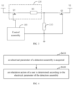
- the detection assembly 130 is connected between the heating element 110 and the power supply 120.
- the detection assembly 130 may includes a reference resistor RS and a detection switch Q1.
- a first terminal of the detection switch Q1 is electrically connected to the power supply
- a second terminal of the detection switch Q1 is electrically connected to a first terminal of the reference resistor RS
- a control terminal of the detection switch Q1 is electrically connected to the control assembly 140.
- a second terminal of the reference resistor RS is electrically connected to the heating element 110.
- the control assembly 140 is configured to acquire a first voltage value V1 at the first terminal of the reference resistor RS and a second voltage value V2 at the second terminal of the reference resistor RS, and identify an inhalation action according to changes in the first voltage value V1 and the second voltage value V2.
- the control assembly 140 is further configured to control the detection switch Q1 to be turned on or off to implement turn-on or turn-off the detection mode.
- the voltage value outputted by the power supply 120 is represented as VS.
- the electrical parameter of the detection assembly 130 may include voltage values at both terminals of the reference resistor RS.
- the control assembly 140 controls the detection switch Q1 to be turned on, and the power supply 120 supplies power to the reference resistor RS and the heating element 110 connected in series.
- the control assembly 140 acquires the voltage values at both terminals of the reference resistor RS, that is, the first voltage value V1 and the second voltage value V2.
- the first voltage value V1 is the output voltage value of the power supply 120, so that the first voltage value V1 may be maintained in a relatively stable voltage value range.
- the second voltage value V2 may be affected by the change in the resistance value of the heating element 110.
- the second voltage value V2 can be configured to characterize the resistance value of the heating element 110. Accordingly, whether an inhalation action occurs can be identified by the changes in the first voltage value V1 and the second voltage value V2.
- the control assembly 140 may acquire a plurality of groups of first voltage values V1 and second voltage values V2 in the detection mode. After maximum and minimum values of the first voltage values V1 and the second voltage values V2 are filtered out, an average value of the first voltage values V1 and an average value of the second voltage values V2 are finally adopted to determine whether the inhalation action occurs, thereby reducing the detection error and improving the accuracy of the identification.
- the detection switch Q1 if the internal resistance of the detection switch Q1 is not much different from the resistance value of the heating element 110, the detection switch Q1, the reference resistor RS and the heating element form a series voltage value divider.
- the first voltage value V1 may also change suddenly. At the moment, the first voltage value V1 and the second voltage value V1 are used together to identify the inhalation action, the accuracy of the identification can still be guaranteed.
- control assembly 140 controls the detection switch Q1 to be turned off, so that the branch where the reference resistor RS is located is cut off.
- the power supply 120 supplies power to the heating element 110 through another branch.
- the detection switch Q1 may be an electronic switch such as a triode, a metal oxide semiconductor (MOS) transistor, or an insulated-gate bipolar transistor (IGBT).
- MOS metal oxide semiconductor
- IGBT insulated-gate bipolar transistor
- the electrical parameter of the detection assembly 130 may also be the resistance value of the reference resistor RS, the power of the reference resistor RS, or the current flowing through the reference resistor RS.
- control assembly 140 controls the detection switch Q1 to be turned on for a preset duration according to the preset period.
- the detection switch Q1 is controlled to be turned off when the turn-on duration reaches a preset duration.
- the control assembly 140 acquires the first voltage value V1 and the second voltage value V2 when the detection switch Q1 is turned on.
- the preset period may be 10 ms
- the preset duration may be 250 ⁇ s.
- control assembly 140 is configured to calculate an inhalation state quantity according to the first voltage value V1 and the second voltage value V2, and determine that the inhalation action occurs when an absolute value of a difference between an inhalation state quantity at a current moment and an inhalation state quantity at a previous moment is greater than a preset threshold value.
- the suction state quantity is a physical quantity for characterizing changes in the voltage values at both terminals of the reference resistor RS.
- the preset threshold value is a reference value reflecting changes in the voltage values at both terminals of the reference resistor RS when no inhalation action occurs and the heating element 110 is in a heating state. If the inhalation action is directly determined according to the first voltage value V1 and the second voltage value V2, there may exist a large error, and due to the power of the power supply 120 or other reasons, the first voltage value V1 and the second voltage value V2 may have abnormal changes.
- the inhalation state quantity may be a difference value between the first voltage value V1 and the second voltage value V2, or a change rate of the difference value between the first voltage value V1 and the second voltage value V2.
- the preset threshold value may be equal to 0.08.
- the inhalation state quantity is equal to the difference value between the first voltage value V1 and the second voltage value V2 multiplied by the second voltage value V2.
- Table 1 shows an embodiment, in an inhalation period, the inhalation state quantity K is calculated by the MCU according to the collected first voltage value V1 and second voltage value V2, and the absolute value K of the difference between the inhalation state quantities at two adjacent moments changes with time.
- K when no inhalation action occurs, K is stabilized below a preset reference value, such as 0.01. And after one inhalation action occurs, the resistance value of the heating element may gradually increase as heating up and return to a steady-state value, during which K may remain greater than the preset reference value. Therefore, after it is determined that the inhalation action occurs, it is determined that the inhalation action occurs again only when K increases again to exceed the preset threshold value after the K is identified to be lower than the preset reference value, and then it is determined that the inhalation action occurs again.
- a preset reference value such as 0.01.
- control assembly 140 is further configured to update the record of the number of times of inhalation when it is determined that an inhalation action occurs.
- control assembly 140 When determining that the inhalation action occurs, the control assembly 140 adds 1 to the number of times of inhalation and update the record of the number of times of inhalation.
- the aerosol generation device may further include a power switch Q2.
- a first terminal of the power switch Q2 is connected to the heating element 110, a second terminal of the power switch Q2 is electrically connected to the power supply 120, and a control terminal of the power switch Q2 is electrically connected to the control assembly 140.
- the control assembly 140 is configured to transmit a PWM signal to control turn-on and turn-off of the power switch Q2 in a heating atomization mode, and is further configured to switch and control the power switch Q2 or the detection switch Q1 to be turned on, to implement the switching between the heating atomization mode and the detection mode.
- the control assembly 140 controls the turn-on and turn-off of the power switch Q2 by transmitting a PWM signal, to implement the power control of the heating element 110, i.e., the temperature control of the heating element 110.
- the control assembly 140 outputs a PWM signal to the power switch Q2 to control the turn-on or turn-off of the power switch Q2, to regulate the power outputted to the heating element 110 and implement the temperature control.
- the temperature control can be performed according to a preset temperature curve.
- the control assembly 140 controls the power switch Q2 to be turned off, and controls the detection switch Q1 to be turned on. After the detection is completed, the control assembly 140 controls the detection switch Q1 to be turned off, and continues to control the operation of the power switch Q2 by transmitting a PWM signal.
- a control method for an aerosol generation device is further provided, which is applied to the control assembly for the aerosol generation device as an example for description.
- the control method may include the following steps.
- Step 410 an electrical parameter of a detection assembly is acquired.
- Step 420 an inhalation action of a user is determined according to the electrical parameter of the detection assembly.
- the detection assembly is connected between the heating element and the power supply.
- the detection assembly may include a reference resistor and a detection switch.
- a first terminal of the reference resistor is electrically connected to the power supply via the detection switch, and a second terminal of the reference resistor is electrically connected to the heating element.
- the voltage values at both terminals of the detection assembly includes a first voltage value at the first terminal and a second voltage value at the second terminal of the reference resistor.
- the step of determining the inhalation action of the user according to the changes in the voltage values at both terminals of the detection assembly may include:
- the inhalation state quantity may be equal to the difference value between the first voltage value and the second voltage value multiplied by the second voltage value.
- control method may further include: when it is determined that the inhalation action occurs, a record of the times of inhalation is updated.
- steps in the flow chart of FIG. 4 are displayed sequentially as indicated by the arrows, these steps are not definitely executed sequentially in the order indicated by the arrows. Unless otherwise specified herein, there is no strict order limitation for the execution of these steps, and these steps may be executed in other orders. Moreover, at least part of the steps in FIG. 4 may include multiple steps or multiple stages. These steps or stages are not definitely executed at the same time, but can be executed at different moments. The execution order of these steps or stages is not definitely sequential, but can be executed in turns or alternately with other steps or at least part of the steps or stages in other steps.
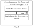
- a control apparatus 500 for an aerosol generation device may include:
- the inhalation action determination module 520 may include:
- control apparatus may further include: a counting module configured to update a record of the number of times of inhalation when it is determined that the inhalation action occurs.
- Modules in the above control apparatus can be fully or partially implemented by software, hardware or a combination thereof.
- the above modules may be embedded in or independent of a processor in a computer device in the form of hardware, or may be stored in a memory in a computer device in the form of software, so that the processor can invoke and execute operations corresponding to the above modules.
- the division of modules in the embodiments of the present invention is schematic and is merely a logical function division. There may exist other division modes in actual implementations.
- an aerosol generation device is provided.
- the aerosol generation device is configured to provide an aerosol when the user inhales the aerosol through the aerosol generation device.
- the aerosol generation device may include:
- the processor when executing the computer program, may further implement the following steps of:
- the processor when executing the computer program, may further implement the following step of: updating a record of the number of times of inhalation when determining that the inhalation action occurs.
- a computer-readable storage medium on which a computer program is stored.
- the computer program when executed by a processor, may cause the processor to implement the following steps of:
- the computer program when executed by the processor, may cause the processor to further implement the following steps of:
- the computer program when executed by the processor, may cause the processor to further implement the following step of: updating a record of the number of times of inhalation when determining that the inhalation action occurs.
- any reference to memory, storage, database or other media used in the embodiments provided in the present invention may include at least one of non-transitory memory and transitory memory.
- the non-transitory memory may include a read-only memory (ROM), a magnetic tape, a floppy disk, a flash memory or an optical storage, etc.
- the transitory memory may include a Random Access Memory (RAM) or an external cache memory.
- the RAM may be in various forms, such as a static random access memory (SRAM) or a dynamic random access memory (DRAM).
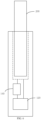
- the aerosol generation device may be a heat-not-burn electronic cigarette
- the aerosol-forming substrate may be a solid aerosol-forming substrate 200.
- the solid aerosol-forming substrate 200 is inserted into the aerosol generation device and heated to generate the aerosol for inhalation by the user.
- the aerosol generation device may be configured to use a liquid aerosol-forming substrate for atomization.
- a liquid storage chamber 150 configured to receive the aerosol-forming substrate is provided in the aerosol generation device.
- the heating element heats the aerosol-forming substrate in the liquid storage chamber to generate the aerosol for inhalation by the user.
Landscapes
- Infusion, Injection, And Reservoir Apparatuses (AREA)
- Control Of Resistance Heating (AREA)
Applications Claiming Priority (2)
| Application Number | Priority Date | Filing Date | Title |
|---|---|---|---|
| CN202210044755.6A CN114376274B (zh) | 2022-01-14 | 2022-01-14 | 气溶胶产生装置及其控制方法、控制装置和存储介质 |
| PCT/CN2022/138393 WO2023134358A1 (zh) | 2022-01-14 | 2022-12-12 | 气溶胶产生装置及其控制方法、控制装置和存储介质 |
Publications (2)
| Publication Number | Publication Date |
|---|---|
| EP4464178A1 true EP4464178A1 (de) | 2024-11-20 |
| EP4464178A4 EP4464178A4 (de) | 2025-04-30 |
Family
ID=81201754
Family Applications (1)
| Application Number | Title | Priority Date | Filing Date |
|---|---|---|---|
| EP22919991.4A Pending EP4464178A4 (de) | 2022-01-14 | 2022-12-12 | Aerosolerzeugungsvorrichtung, steuerungsverfahren dafür, steuerungsvorrichtung und speichermedium |
Country Status (5)
| Country | Link |
|---|---|
| EP (1) | EP4464178A4 (de) |
| JP (1) | JP7793795B2 (de) |
| KR (1) | KR20240126065A (de) |
| CN (1) | CN114376274B (de) |
| WO (1) | WO2023134358A1 (de) |
Families Citing this family (8)
| Publication number | Priority date | Publication date | Assignee | Title |
|---|---|---|---|---|
| CN114376274B (zh) * | 2022-01-14 | 2024-01-30 | 深圳麦时科技有限公司 | 气溶胶产生装置及其控制方法、控制装置和存储介质 |
| CN114947234A (zh) * | 2022-06-06 | 2022-08-30 | 海南摩尔兄弟科技有限公司 | 雾化控制方法及电子雾化器 |
| CN117491758A (zh) * | 2022-07-25 | 2024-02-02 | 深圳麦时科技有限公司 | 故障检测方法及其装置、可读存储介质和气溶胶雾化装置 |
| CN117731066A (zh) * | 2022-09-15 | 2024-03-22 | 深圳麦时科技有限公司 | 气溶胶生成设备及其控制方法、控制装置 |
| CN119423402A (zh) * | 2023-07-28 | 2025-02-14 | 深圳市合元科技有限公司 | 抽吸口数计量方法和气溶胶生成装置 |
| CN120827224A (zh) * | 2024-04-23 | 2025-10-24 | 深圳市合元科技有限公司 | 气溶胶生成装置及控制方法 |
| CN121153933A (zh) * | 2024-06-17 | 2025-12-19 | 思摩尔国际控股有限公司 | 一种加热不燃烧装置及其抽吸检测方法 |
| CN119606082B (zh) * | 2024-12-30 | 2025-09-19 | 湖北中烟工业有限责任公司 | 一种抽吸口数检测方法及系统 |
Family Cites Families (18)
| Publication number | Priority date | Publication date | Assignee | Title |
|---|---|---|---|---|
| EP2110033A1 (de) * | 2008-03-25 | 2009-10-21 | Philip Morris Products S.A. | Verfahren zum Steuern der Bildung von Rauchbestandteilen in einem elektrischen Aerosolerzeugungssystem |
| EP2143346A1 (de) * | 2008-07-08 | 2010-01-13 | Philip Morris Products S.A. | Durchfluss-Sensor System |
| WO2014172906A1 (zh) * | 2013-04-27 | 2014-10-30 | 吉瑞高新科技股份有限公司 | 一种基于电子烟盒的充电方法及相应的电子烟盒 |
| FR3017954B1 (fr) * | 2014-02-21 | 2016-12-02 | Smokio | Cigarette electronique |
| WO2018027189A2 (en) * | 2016-08-05 | 2018-02-08 | Juul Labs, Inc. | Anemometric-assisted control of a vaporizer |
| DE102017104944B4 (de) * | 2017-03-09 | 2018-12-20 | Sick Ag | Flächensauggreifer zum Aufnehmen eines Werkstückes |
| RU2764604C2 (ru) * | 2017-10-05 | 2022-01-18 | Филип Моррис Продактс С.А. | Электрически управляемое устройство, генерирующее аэрозоль, с непрерывным регулированием подачи мощности |
| WO2019077710A1 (ja) * | 2017-10-18 | 2019-04-25 | 日本たばこ産業株式会社 | 吸引成分生成装置、吸引成分生成装置を制御する方法、及びプログラム |
| KR102500895B1 (ko) * | 2018-01-26 | 2023-02-17 | 니뽄 다바코 산교 가부시키가이샤 | 에어로졸 생성 장치 및 이것을 동작시키는 방법 및 프로그램 |
| CN110150751A (zh) * | 2018-02-10 | 2019-08-23 | 常州市派腾电子技术服务有限公司 | 发热元件、雾化器及电子烟 |
| CN109007976B (zh) * | 2018-06-20 | 2021-07-16 | 湖北中烟工业有限责任公司 | 具有抽吸口数计数功能的电加热装置 |
| CN109907371B (zh) * | 2019-01-22 | 2021-06-18 | 河南中烟工业有限责任公司 | 基于加热不燃烧卷烟中的自适应温度电路的控制方法 |
| CN210143834U (zh) * | 2019-05-14 | 2020-03-17 | 惠州市沛格斯科技有限公司 | 电子烟具的计算电路及电子烟具 |
| CN113519909A (zh) * | 2020-04-22 | 2021-10-22 | 深圳市合元科技有限公司 | 气溶胶生成装置及其控制方法 |
| CN112403405B (zh) * | 2020-10-15 | 2023-01-03 | 深圳麦克韦尔科技有限公司 | 气溶胶产生装置、气溶胶产生方法、控制电路及存储介质 |
| CN113080525A (zh) * | 2021-03-17 | 2021-07-09 | 深圳麦克韦尔科技有限公司 | 气溶胶产生装置、干烧检测方法及计算机程序产品 |
| CN113519918A (zh) * | 2021-06-25 | 2021-10-22 | 深圳麦时科技有限公司 | 气溶胶形成装置及其抽吸检测方法、计算机存储介质 |
| CN114376274B (zh) * | 2022-01-14 | 2024-01-30 | 深圳麦时科技有限公司 | 气溶胶产生装置及其控制方法、控制装置和存储介质 |
-
2022
- 2022-01-14 CN CN202210044755.6A patent/CN114376274B/zh active Active
- 2022-12-12 KR KR1020247025584A patent/KR20240126065A/ko active Pending
- 2022-12-12 WO PCT/CN2022/138393 patent/WO2023134358A1/zh not_active Ceased
- 2022-12-12 EP EP22919991.4A patent/EP4464178A4/de active Pending
- 2022-12-12 JP JP2024541083A patent/JP7793795B2/ja active Active
Also Published As
| Publication number | Publication date |
|---|---|
| WO2023134358A1 (zh) | 2023-07-20 |
| CN114376274A (zh) | 2022-04-22 |
| CN114376274B (zh) | 2024-01-30 |
| JP2024545930A (ja) | 2024-12-13 |
| KR20240126065A (ko) | 2024-08-20 |
| EP4464178A4 (de) | 2025-04-30 |
| JP7793795B2 (ja) | 2026-01-05 |
Similar Documents
| Publication | Publication Date | Title |
|---|---|---|
| KR20240126065A (ko) | 에어로졸 생성 장치 및 이의 제어방법, 제어장치 및 저장매체 | |
| EP4458192A1 (de) | Aerosolerzeugungsvorrichtung, steuerungsverfahren und steuerungsvorrichtung dafür sowie speichermedium | |
| EP3771351B1 (de) | Elektronische zerstäubungsvorrichtungen, verfahren zur heizungssteuerung und computerprogrammprodukte | |
| KR20220056227A (ko) | 전자 담배 장치 및 그 가열 방법, 컴퓨터 저장 매체 | |
| CN109330032B (zh) | 一种电子烟控制方法及电子烟 | |
| EP3682750A1 (de) | Elektronische zerstäubungsvorrichtung, verfahren zur steuerung des heizelements einer elektronischen zerstäubungsvorrichtung und speichermedium | |
| RU2600093C1 (ru) | Устройство и способ для управления электрическим испарителем | |
| EP3249488A1 (de) | Temperaturregelungssystem und regelungsverfahren dafür und elektronische zigarette mit besagtem temperaturregelungssystem | |
| WO2022267145A1 (zh) | 一种工作参数校准方法、装置及计算机可读存储介质 | |
| US20210321675A1 (en) | Electronic Cigarette Control Method and Electronic Cigarette | |
| JP2013239425A (ja) | バッテリ温度検出および寄生抵抗補償システム | |
| WO2019223531A1 (zh) | 确定电子烟输出功率的方法、电子烟及计算机存储介质 | |
| JPS6338534B2 (de) | ||
| US20210195960A1 (en) | Control circuit and electronic cigarette | |
| CN110025052B (zh) | 雾化器的电压控制方法、装置和电子烟 | |
| JP2767892B2 (ja) | 放電加工機用電源 | |
| CN114009847B (zh) | 用于电子雾化装置的控制单元、电子雾化装置、控制方法 | |
| CN108966395B (zh) | 电磁加热系统、igbt的驱动控制电路及其的故障检测方法 | |
| CN120467528A (zh) | 温度检测电路、方法和电子设备 | |
| CN116456512B (zh) | 预热时长的确定方法和加热设备 | |
| CN115167573B (zh) | 液体处理装置及其控制方法、装置和可读存储介质 | |
| CN117918590A (zh) | 雾化器的干烧检测方法、装置、控制器和雾化设备 | |
| CN116268577A (zh) | 一种雾化设备控制方法、装置及计算机可读存储介质 | |
| CN115209578B (zh) | 电热器具的控制方法及装置、控制器、电热器具 | |
| CN115425825A (zh) | 一种脉宽调制控制开关管的方法、装置、控制器和逆变器 |
Legal Events
| Date | Code | Title | Description |
|---|---|---|---|
| STAA | Information on the status of an ep patent application or granted ep patent |
Free format text: STATUS: THE INTERNATIONAL PUBLICATION HAS BEEN MADE |
|
| PUAI | Public reference made under article 153(3) epc to a published international application that has entered the european phase |
Free format text: ORIGINAL CODE: 0009012 |
|
| STAA | Information on the status of an ep patent application or granted ep patent |
Free format text: STATUS: REQUEST FOR EXAMINATION WAS MADE |
|
| 17P | Request for examination filed |
Effective date: 20240801 |
|
| AK | Designated contracting states |
Kind code of ref document: A1 Designated state(s): AL AT BE BG CH CY CZ DE DK EE ES FI FR GB GR HR HU IE IS IT LI LT LU LV MC ME MK MT NL NO PL PT RO RS SE SI SK SM TR |
|
| REG | Reference to a national code |
Ref country code: DE Ref legal event code: R079 Free format text: PREVIOUS MAIN CLASS: A24F0040400000 Ipc: A24F0040510000 |
|
| DAV | Request for validation of the european patent (deleted) | ||
| DAX | Request for extension of the european patent (deleted) | ||
| A4 | Supplementary search report drawn up and despatched |
Effective date: 20250331 |
|
| RIC1 | Information provided on ipc code assigned before grant |
Ipc: A24F 40/57 20200101ALN20250325BHEP Ipc: A24F 40/53 20200101ALN20250325BHEP Ipc: A24F 40/50 20200101ALI20250325BHEP Ipc: A24F 40/51 20200101AFI20250325BHEP |