EP4464199A2 - Meuble d'assise, notamment chaise haute pour enfants - Google Patents
Meuble d'assise, notamment chaise haute pour enfants Download PDFInfo
- Publication number
- EP4464199A2 EP4464199A2 EP24205105.0A EP24205105A EP4464199A2 EP 4464199 A2 EP4464199 A2 EP 4464199A2 EP 24205105 A EP24205105 A EP 24205105A EP 4464199 A2 EP4464199 A2 EP 4464199A2
- Authority
- EP
- European Patent Office
- Prior art keywords
- locking
- high chair
- children according
- height
- chair
- Prior art date
- Legal status (The legal status is an assumption and is not a legal conclusion. Google has not performed a legal analysis and makes no representation as to the accuracy of the status listed.)
- Pending
Links
Images

Classifications
-
- A—HUMAN NECESSITIES
- A47—FURNITURE; DOMESTIC ARTICLES OR APPLIANCES; COFFEE MILLS; SPICE MILLS; SUCTION CLEANERS IN GENERAL
- A47D—FURNITURE SPECIALLY ADAPTED FOR CHILDREN
- A47D1/00—Children's chairs
- A47D1/002—Children's chairs adjustable
-
- A—HUMAN NECESSITIES
- A47—FURNITURE; DOMESTIC ARTICLES OR APPLIANCES; COFFEE MILLS; SPICE MILLS; SUCTION CLEANERS IN GENERAL
- A47C—CHAIRS; SOFAS; BEDS
- A47C3/00—Chairs characterised by structural features; Chairs or stools with rotatable or vertically-adjustable seats
- A47C3/20—Chairs or stools with vertically-adjustable seats
- A47C3/28—Chairs or stools with vertically-adjustable seats with clamps acting on vertical rods
-
- A—HUMAN NECESSITIES
- A47—FURNITURE; DOMESTIC ARTICLES OR APPLIANCES; COFFEE MILLS; SPICE MILLS; SUCTION CLEANERS IN GENERAL
- A47D—FURNITURE SPECIALLY ADAPTED FOR CHILDREN
- A47D1/00—Children's chairs
- A47D1/002—Children's chairs adjustable
- A47D1/004—Children's chairs adjustable in height
-
- A—HUMAN NECESSITIES
- A47—FURNITURE; DOMESTIC ARTICLES OR APPLIANCES; COFFEE MILLS; SPICE MILLS; SUCTION CLEANERS IN GENERAL
- A47D—FURNITURE SPECIALLY ADAPTED FOR CHILDREN
- A47D1/00—Children's chairs
- A47D1/008—Children's chairs with trays
-
- A—HUMAN NECESSITIES
- A47—FURNITURE; DOMESTIC ARTICLES OR APPLIANCES; COFFEE MILLS; SPICE MILLS; SUCTION CLEANERS IN GENERAL
- A47D—FURNITURE SPECIALLY ADAPTED FOR CHILDREN
- A47D1/00—Children's chairs
- A47D1/008—Children's chairs with trays
- A47D1/0083—Children's chairs with trays movable to inoperative position
-
- A—HUMAN NECESSITIES
- A47—FURNITURE; DOMESTIC ARTICLES OR APPLIANCES; COFFEE MILLS; SPICE MILLS; SUCTION CLEANERS IN GENERAL
- A47D—FURNITURE SPECIALLY ADAPTED FOR CHILDREN
- A47D15/00—Accessories for children's furniture, e.g. safety belts or baby-bottle holders
Definitions
- the invention relates to a piece of seating furniture, in particular a high chair for children according to claim 1.
- High chairs for children have been known for a long time and in various designs.
- such high chairs comprise a frame with a pair of front chair legs and a pair of rear chair legs (or alternatively, for example, only two chair legs that are appropriately extended at their lower end to ensure stability) and a seat with a seat and a backrest. Additional elements may include armrests, a footrest, a storage area ("tray”) and the like.
- the frame (with or without a seat) may optionally be foldable to enable a use position and a (more compact) folded position.
- the seat may be in a fixed position relative to the frame or may be adjustable in height, whereby either the entire seat is adjusted or individual components such as the seat and/or the backrest and/or the footrest (which may then be adjusted independently of each other).
- a certain number of predetermined positions (height positions) are made possible for the adjustable components, for example by forming holes at suitable locations on the frame and (retractable) pins on the component to be adjusted.
- An adjustable child seat is made of DE 690 09 806 T2 known.
- DE 690 098 06 T2 Two pins (one on each side of the high chair) are provided for height adjustment, which can take on different, discrete positions in a guide track, so that the high chair can be adjusted in height.
- similar solutions are available from US 5 238 292 A as well as US 4 722 570 A known.
- Locking elements are provided which can be engaged with corresponding ribs so that the height can also be adjusted.
- the object is achieved by a piece of seating furniture, in particular a child's chair, preferably a high chair for children, with a height-adjustable support device for supporting a body part and/or an external object, such as a drinking bottle or a toy, of the child, wherein the height adjustment device comprises a locking device which locks a set height, at least partially, in particular predominantly, by means of a frictional connection (in particular by means of a press fit and/or a jamming).
- the above object is achieved in particular by a piece of seating furniture, in particular a children's chair, preferably a high chair for children, with a height-adjustable support device for supporting a part of the child's body, comprising a height adjustment device which is configured for the continuous height adjustment of the support device.
- a key idea of the invention is to lock a certain height (of a height-adjustable support device) at least partially (in particular predominantly) by means of a force connection (or frictional connection).
- a force connection there is a normal force between surfaces to be locked against each other. The locking can only be overcome if an applied force exceeds the counterforce caused by the static friction.
- in a form connection at least two parts to be connected engage with each other. As a result, in a form connection the parts to be connected cannot separate from each other even without or with interrupted force transmission.
- one part to be connected is in the way of the other. Under operating load, pressure forces act normally, i.e. at right angles to the surfaces of the parts to be connected.
- Such form connections are used, for example, in US 4 722 570 A , US 5 238 292 A as well as DE 690 09 806 T2 described.
- the locking device is configured in such a way that a locking can only be maintained (under load) if the frictional connection is also effective. In other words, a locking is only maintained if the frictional connection is effective, or not maintained if the frictional connection is at least mentally removed (or the holding force of the frictional connection is at least mentally disregarded). This should apply at least to a state of the respective support device in which the weight of the support device is effective.
- an additional load of preferably at least 5 kg, more preferably at least 10 kg (as the weight of the child) can be taken into account here.
- An upper limit for the weight to be added (simulating the child) on the Support device can be ⁇ 60 kg, preferably ⁇ 40 kg.
- locking should at least be partly caused by the frictional connection (in the sense that without the frictional connection, at least in sections of this range, the locking would not hold).
- a force that can be compensated by the frictional connection is ⁇ 50 Newtons, more preferably ⁇ 200 Newtons, even more preferably ⁇ 300 Newtons.
- Locking should predominantly be caused by the frictional connection, in particular when at least 50%, preferably at least 80% of a holding force is applied (in particular under the circumstances mentioned above, for example concerning additional weight from a child sitting in the chair).
- the locking is completely achieved by the frictional connection in particular when the entire force can be compensated by the frictional connection (or the locking can be maintained by the frictional connection).
- the height adjustment device is preferably configured in such a way that an adjustment is possible within a height difference (in the vertical direction) of at least 5 cm, preferably at least 10 cm, even more preferably at least 15 cm.
- This height adjustment is preferably continuous if any height values can be set within this height difference (or at least height values that are ⁇ 2 mm, in particular ⁇ 0.5 mm apart from one another).
- a first height adjustment range can also be provided in which the height is continuously adjustable and a second height adjustment range in which only a discrete height adjustment is possible. In one embodiment, however, a continuous height adjustment can be made across the entire height adjustment range (of the respective support device).
- a height difference of the continuously adjustable height range is in particular at least 2 cm, more preferably at least 5 cm, even more preferably at least 10 cm.
- the locking device can be configured in such a way that it locks the set height, at least partially, in particular predominantly, by means of a press fit and/or a clamping.
- a press fit is to be understood in particular as a configuration in which a force (for example by a spring) is applied in the direction of one or more Adhesive surfaces act so that the surfaces adhering to one another are pressed against one another.
- a projection or pin (or the like) can be pressed into a corresponding recess.
- a clamp (or a corresponding clamping device) is to be understood in particular as a device that acts in such a way that an increase in the loading force (for example when a child climbs onto the seat, in particular the high chair) causes an increase in the force due to the frictional connection (friction force) (comparable to a wedge clamped under a door gap).
- an increase in the loading force for example when a child climbs onto the seat, in particular the high chair
- the frictional connection for example when a child climbs onto the seat, in particular the high chair
- the support device may comprise a seat and/or a backrest and/or a footrest and/or an armrest and/or a storage area (for drinking cups and the like).
- the locking device can comprise (at least) one locking groove and at least one locking element that can be guided into and out of the locking groove.
- the locking element is preferably secured in the locked state within the locking groove by a press fit and/or a clamping. With such a configuration, a continuous adjustment of the locking can be made possible in a simple manner.
- the locking groove can be arranged on a main body (e.g. frame) of the seating furniture, in particular a high chair, and the (at least one) locking element on the support device, or vice versa.
- the interchangeability of the arrangement of components that can be connected to one another by frictional locking also applies in principle to other possible embodiments of the invention (as described below, for example).
- a locking mechanism can preferably be established or released by rotating a locking element and/or by a translatory movement of a locking element.
- the locking element can be rotated into the locking groove in order to effect a locking mechanism. This enables a locking mechanism to be achieved in a simple manner.
- the actuating element is pre-tensioned, in particular in the direction of a locking position (or in a direction in which the actuating element is forced into the locking position by a pre-tensioning force). This further simplifies handling.
- a locking mechanism can be established and/or released by rotating an actuating element and/or by a translational movement of an actuating element.
- An actuating element is understood to mean in particular a handling device (e.g. comprising a handle) that is accessible from the outside so that a user can grasp it (to release or establish the locking mechanism).
- a handling device can be arranged, for example, in a central region of the seating furniture, in particular a high chair.
- at least two or more locking devices can be actuated via one and the same actuating element (or handling device) (so that a locking mechanism is released or established).
- the actuating element and locking element can be operatively connected to one another via a connecting device (which can be moved translationally or purely translationally if necessary).
- the actuating element is rotatable and arranged in such a way that it drives a (translationally movable) connecting device, which in turn rotates one (or more) locking elements to establish or release the locking.
- a (translationally movable) connecting device which in turn rotates one (or more) locking elements to establish or release the locking.
- a pre-tensioning device in particular a spring device, is provided, which preferably acts in the direction of a locked state.
- a spring device (or possibly another spring device) can also be provided, which acts in the direction of a non-locked state.
- a pre-tensioning device in particular a spring device, is provided, which acts in the direction of a locked state, a lock can be established and maintained in a simple (and safe) manner.
- a pre-tensioning device in particular a spring device, provides a predefined force that does not depend on the respective usage situation (e.g. weight of the child).
- the height adjustment is positively guided. This simplifies handling.
- a positive guide can, for example, comprise a rail and/or groove and/or guide.
- a guide groove is provided for guiding a height adjustment.
- the guide groove is preferably formed at least partially by the locking groove described above (or vice versa).
- the guide and/or locking groove is designed such that the locking element described above can slide in the guide or locking groove in the non-locked state.
- a (further) sliding element can be provided which can slide in the guide or locking groove (to guide or control the height adjustment).
- the sliding element is provided in particular in addition to the locking element.
- the sliding element can be designed as a (possibly concave, in particular cylinder jacket section-shaped) plate (i.e. as a sliding plate) which can be moved accordingly in the groove.
- the locking element preferably penetrates the sliding element (in particular an opening in the same, which can be slot-shaped, for example). Overall, this simplifies handling.
- a locking element which can be guided into and out of the locking groove, this does not necessarily mean that the locking element must be able to be guided completely out of the locking groove (which may, however, be the case), but it is sufficient in this sense if the locking element can be guided at least partially out of the locking groove (in particular in the sense that a distal end of the locking element can be further removed from a groove base).
- a combined guide and locking groove allows for easy adjustment and locking in a structurally simple design.
- the locking device can be arranged and configured in such a way that gravity (of the support device itself and possibly of a child placed on the support device) at least supports the locking. Gravity can, for example, be directed (redirected) in such a way that it causes an increase in the normal force of surfaces in static friction with one another.
- the locking device has two locking elements (preferably rotatable in opposite directions).
- the two locking elements can optionally engage in the same recess (e.g. groove).
- the two rotatable locking elements are preferably guided in such a way (for example by a common contact surface at the proximal ends of the locking elements) that they can only be rotated together.
- the two locking elements are preferably mounted on a common axis.
- one or more locking elements can be mounted on the rotation axis, which is stationary relative to a main body (e.g. frame) of the seating furniture, in particular a high chair. If two locking elements (in particular those that can be rotated in opposite directions) are provided, it can be provided in particular that a first locking element enables locking against a downward movement (at least predominantly) and a second locking element enables locking against an upward movement (at least predominantly). Furthermore, it can be the case that the rotation of the locking elements (for example by rotating the locking elements towards each other) enables a further force (e.g. due to a spreading) that further improves the locking.
- a further force e.g. due to a spreading
- the one or more locking elements can be wedge-shaped in a cross-section (in particular radial section) or, if necessary, flat.
- each support device preferably two, in particular one on each side of the seating furniture, in particular the high chair. This enables reliable locking.
- the height adjustment and/or the locking of the set height and/or the release of the locking of the set height can be carried out with one hand.
- both the height adjustment and the locking of the set height as well as the release of the locking of the set height can be carried out by grasping and operating a (single) handle.
- the height adjustment by raising or lowering (or allowing it to be lowered) the handle (i.e. generally by a translatory movement if necessary) and locking the set height or releasing the locking of the set height by rotating the handle.
- the handle as such is preferably formed in one piece or monolithically.
- the handle can be arranged in the middle.
- the handle can have a concave outer surface (for gripping).
- the size (length) of the handle can be at least 5 cm, preferably at least 10 cm and/or at most 30 cm, preferably at most 20 cm. Overall, handling the child seat is made much easier.
- At least one or more locking elements are preferably rotated downwards (at least in the locked state, possibly in all possible states).
- a load that acts, for example, on the axis about which the respective locking element can be pivoted, leads to a further extension (pivoting upwards) of the locking element, so that the locking element basically pivots further outwards and thus an adhesive force (friction force) is increased.
- an adhesive force vibration force
- a piece of seating furniture in particular a high chair, which has a height-adjustable component, wherein a locking (fixing) of the height adjustment can preferably be effected by a clamping device (clamping element).
- the clamping device in particular acting like a wedge
- the clamping device can be arranged on a main body of the seating furniture, in particular a high chair (e.g. frame) and designed to be brought into engagement with the height-adjustable component - or vice versa.
- the locking (clamping device) can be brought into a locking position in which a relative movement between the main body of the seating furniture, in particular a high chair, and the height-adjustable component is prevented, or into a released state where such a relative movement is possible.
- a transition between the locked state and the released state is preferably made possible by rotation, but can also take place translationally.
- a clamping device or a locking element is pre-tensioned in the direction of the locking state, for example by a spring or other (suitable pre-tensioning device).
- a relative movement is guided between the main body of the seating furniture, in particular the high chair, and the height-adjustable component, so that the relative movement follows (or must follow) a predetermined trajectory. Continuous (stepless) positioning can be possible on this trajectory.
- a groove can be provided as a guide means on the element (either the main body or the height-adjustable component) that does not comprise the spring element (or the clamping device).
- the locking element or the clamping device
- the locking element can be brought into engagement with an inner surface of the groove.
- the locking element or the clamping device
- the locking element can preferably transition from a released state to a locked state by rotation.
- the rotation preferably takes place in such a way (or in such a direction of rotation) that a force in the direction of gravity (or along a guide device, such as a guide groove) at least partially (or completely) effects the engagement (the locking).
- two locking elements clampping devices can be provided, which can be rotated in different directions, so that for each force (with a component in one direction of a possible movement) at least one of the locking elements (or clamping devices) effects a locking.
- the seating furniture in particular the high chair or the height-adjustable component, to be equipped with two or more locking elements (clamping devices or locking devices) or corresponding pairs of locking elements (or clamping devices) which can be released and/or transferred to the locked state by means of a common mechanism.
- the seating furniture in particular the high chair, may comprise a frame, possibly with a pair of front chair legs and a pair of rear chair legs (or alternatively, for example, only three or only two chair legs, which may be attached to their lower end are extended accordingly to ensure stability) and a seat with a seat and optionally a backrest. Additional elements can include armrests, a footrest and/or a storage area ("tray").
- the frame (with or without seat) can be foldable if necessary to allow a use position and a (more compact) folded position.
- the invention not only includes a height adjustment (even if the present invention is particularly advantageous for a height adjustment, since it is particularly important here that the child or other objects can be positioned as precisely as possible), but also generally an adjustment of another position of the support device, in particular a depth adjustment (i.e. in particular an adjustment of the support device further forwards or further back).
- a depth adjustment i.e. in particular an adjustment of the support device further forwards or further back.
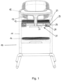
- Fig. 1 shows a high chair 10 with legs 11, a seat 12, a backrest 13, a footrest 14 and a storage area (tray) 15.
- the seat 12 and the footrest 14 are (independently of each other) adjustable in terms of their height in relation to the legs 11.
- the mechanism for adjusting the height is analogous for the seat 12 and the footrest 14, so that only the mechanism for adjusting the height of the seat 12 is explained in detail below.
- the height adjustment of the seat surface 12 is positively guided by means of a (guide) groove 29.
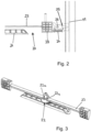
- the seat surface 12 generally comprises a (symmetrical) locking device 20.
- the locking device 20 has an actuating device (lever) 21 and a stabilizing strut or a housing 27.
- On each side of the locking device there are also a force transmission device (rod) 23, a spring 24, a contact element 28 (at the end of the force transmission device 23), which can be designed as a pressure plate, and two locking elements 25 or clamping devices 25 (see Fig. 2 and 3 ) is provided.
- the spring biases the locking elements 25 against each other in a locked state, whereby these locking elements 25 are brought into engagement with a (associated) leg 11 of the high chair 10, specifically with a groove 29 provided there.
- this groove is formed by the above-mentioned (guide) groove 29.
- the actuating device 21 has a (round) central section 22 and (in the present case two) recesses 22a, wherein in the locked state each recess 22a is in engagement with one of the force transmission devices 23 (rods).
- the locking elements 25 (on each side) are pivotally mounted on the housing 27 about a common axis 26.
- the locking device can be transferred from a locked state to a released state by rotating the actuating device 21 so that the force transmission device 23 is moved outwards (since the force transmission device 23 can then no longer remain in engagement with the recesses 22a).
- the contact device (pressure plate) 28 which is arranged at a distal end of the respective force transmission device 23, is also moved outwards and presses against proximal ends of the locking elements 25. Due to this movement, the locking elements 25 pivot about their (common) axis 26 against the tension force of the spring 24 and thus release from the leg 11.
- the spring 24 can pivot the locking elements 25 back so that they are again locked to the leg 11, since in this state the force transmission device 23 is again engaged with the recesses 22a.
- one of the locking elements (clamping devices) 25 can come into clamping engagement with the corresponding groove 29 and thus prevent the seat surface 12 from being moved in the direction of the force.
- Fig. 4 shows a side view of individual elements of a high chair according to the invention.
- This can be Fig. 1 to 3 be trained so that Fig. 4 also as an illustration of further details of the high chair according to the Fig. 1 to 3 can be viewed.
- the sliding plate 30 is not shown.
- This sliding plate 30 can optionally be used in the embodiment according to the Fig. 1 to 3 be provided (or not).
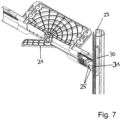
- the sliding plate 30 is shown.
- this sliding plate in particular is in the embodiment according to the Fig. 4 to 7 only optional.
- Fig. 4 to 6 it can be seen that by rotating the actuating device 21 the locking elements 25 are pushed into the groove 29 (see Fig. 4 ) or led out (by swiveling, see Fig. 5 and 6 ).
- the position according to Fig. 4 corresponds to the position according to Fig. 2 .
- Plate 30 (see also Fig. 7 ) has a slot 31 through which the sliding elements 25 (see Fig. 4 ) can penetrate.
- the plate 30 moves when the actuating device 21 moves (upwards or downwards), so that the plate 30 enables reliable guidance of the height adjustment.
- the plate 30 therefore moves in the groove 29 (when the actuating device moves upwards or downwards).
- the locking (arresting) is created between the locking elements 25 and the groove 29.
- the plate 30 has a particularly reinforcing or stabilizing effect and improves guidance in the groove.
- the plate preferably has no (or at best an insignificant) influence on the locking (arresting) as such (however, in a potential alternative embodiment this can also be different).
- Aspect 1 Seating furniture, in particular a high chair (10) for children with a height-adjustable support device (12, 13, 14) for supporting a body part of the child and/or an external object, such as a drinking bottle or a toy, comprising a height adjustment device which comprises a locking device (20) which locks a set height, at least partially, in particular predominantly, by means of a frictional connection.
- a height adjustment device which comprises a locking device (20) which locks a set height, at least partially, in particular predominantly, by means of a frictional connection.
- Aspect 2 Seating furniture, in particular a high chair (10) for children with a height-adjustable support device (12, 13, 14) for supporting a body part of the child, preferably according to claim 1, comprising a height adjustment device for continuously adjusting the height of the support device (12, 13, 14).
- Aspect 3 Seating furniture, in particular a high chair (10) for children according to aspect 1 or 2, wherein the locking device (20) is configured such that it locks the set height, at least partially, in particular predominantly, by means of a press fit and/or a clamping.
- Aspect 4 Seating furniture, in particular a high chair (10) for children according to one of aspects 1-3, wherein the support device comprises a seat (12) and/or a footrest (14).
- Aspect 5 Seating furniture, in particular a high chair (10) for children according to one of aspects 1-4w, wherein the locking device (20) comprises a locking groove (29) and at least one locking element (25) which can be guided into and out of the locking groove (29), which is preferably secured in the locked state within the locking groove (29) by a press fit and/or a clamping.
- the locking device (20) comprises a locking groove (29) and at least one locking element (25) which can be guided into and out of the locking groove (29), which is preferably secured in the locked state within the locking groove (29) by a press fit and/or a clamping.
- Aspect 6 Seating furniture, in particular a high chair (10) for children according to one of aspects 1-5, wherein a locking mechanism can be established and/or released by rotation of a/the locking element (25) and/or by a translational movement of a/the locking element (25).
- Aspect 7 Seating furniture, in particular a high chair (10) for children according to one of the aspects 1-6, wherein a locking is achieved by rotation of an actuating element (21) and/or by a translatory movement of an actuating element (21) can be produced and/or released, wherein the actuating element is prestressed, in particular in the direction of a locking position.
- Aspect 8 Seating furniture, in particular a high chair (10) for children according to one of aspects 1-7, wherein a pre-tensioning device, in particular a spring device (24), is provided which acts in the direction of a locked state.
- a pre-tensioning device in particular a spring device (24)
- Aspect 9 Seating furniture, in particular a high chair (10) for children according to one of the aspects 1-8, wherein a height adjustment is positively guided.
- Aspect 10 Seating furniture, in particular a high chair (10) for children according to one of aspects 1-9, wherein a guide groove (29) is provided for guiding a height adjustment, wherein the guide groove (29) is preferably formed at least partially by the locking groove according to claim 5 or vice versa, in particular such that the locking element (25) can slide in the guide or locking groove (29) in the non-locked state and/or such that an additional sliding element, preferably sliding plate, can slide in the guide or locking groove (29).
- Aspect 11 Seating furniture, in particular a high chair (10) for children according to one of aspects 1-10, wherein the locking device (20) is arranged and configured such that gravity at least supports the locking.
- Aspect 12 Seating furniture, in particular a high chair (10) for children according to one of aspects 1-11, wherein the locking device (20) has two locking elements (25), preferably rotatable in opposite directions.
- Aspect 13 Seating furniture, in particular high chair (10) for children according to one of aspects 1-12, wherein several locking devices (20) are provided per support device, preferably two locking devices, in particular one on each side.
- Aspect 14 Seating furniture, in particular a high chair (10) for children according to one of aspects 1-13, wherein the height adjustment and/or the locking of the set height and/or the release of the locking of the set height can be carried out with one hand.
Landscapes
- Health & Medical Sciences (AREA)
- General Health & Medical Sciences (AREA)
- Pediatric Medicine (AREA)
- Chairs For Special Purposes, Such As Reclining Chairs (AREA)
- Chair Legs, Seat Parts, And Backrests (AREA)
Applications Claiming Priority (4)
| Application Number | Priority Date | Filing Date | Title |
|---|---|---|---|
| DE202017104829 | 2017-08-10 | ||
| DE202017106758.0U DE202017106758U1 (de) | 2017-08-10 | 2017-11-08 | Sitzmöbel, insbesondere Hochstuhl für Kinder |
| EP18750433.7A EP3664665B1 (fr) | 2017-08-10 | 2018-08-06 | Siège, en particulier chaise haute pour enfants |
| PCT/EP2018/071245 WO2019030162A1 (fr) | 2017-08-10 | 2018-08-06 | Siège, en particulier chaise haute pour enfants |
Related Parent Applications (1)
| Application Number | Title | Priority Date | Filing Date |
|---|---|---|---|
| EP18750433.7A Division EP3664665B1 (fr) | 2017-08-10 | 2018-08-06 | Siège, en particulier chaise haute pour enfants |
Publications (2)
| Publication Number | Publication Date |
|---|---|
| EP4464199A2 true EP4464199A2 (fr) | 2024-11-20 |
| EP4464199A3 EP4464199A3 (fr) | 2025-04-30 |
Family
ID=60662008
Family Applications (2)
| Application Number | Title | Priority Date | Filing Date |
|---|---|---|---|
| EP24205105.0A Pending EP4464199A3 (fr) | 2017-08-10 | 2018-08-06 | Meuble d'assise, notamment chaise haute pour enfants |
| EP18750433.7A Active EP3664665B1 (fr) | 2017-08-10 | 2018-08-06 | Siège, en particulier chaise haute pour enfants |
Family Applications After (1)
| Application Number | Title | Priority Date | Filing Date |
|---|---|---|---|
| EP18750433.7A Active EP3664665B1 (fr) | 2017-08-10 | 2018-08-06 | Siège, en particulier chaise haute pour enfants |
Country Status (9)
| Country | Link |
|---|---|
| US (1) | US11297955B2 (fr) |
| EP (2) | EP4464199A3 (fr) |
| JP (1) | JP7677788B2 (fr) |
| KR (1) | KR102712084B1 (fr) |
| CN (2) | CN111163665A (fr) |
| DE (2) | DE202017106758U1 (fr) |
| ES (1) | ES2996336T3 (fr) |
| PL (1) | PL3664665T3 (fr) |
| WO (1) | WO2019030162A1 (fr) |
Families Citing this family (4)
| Publication number | Priority date | Publication date | Assignee | Title |
|---|---|---|---|---|
| JP4951147B1 (ja) * | 2011-09-08 | 2012-06-13 | 積水化学工業株式会社 | 光半導体装置用硬化性組成物 |
| DE202017106758U1 (de) | 2017-08-10 | 2017-11-27 | Cybex Gmbh | Sitzmöbel, insbesondere Hochstuhl für Kinder |
| US12030411B2 (en) | 2022-01-28 | 2024-07-09 | Britax Child Safety, Inc. | Child restraint system with posture fit mechanism |
| WO2025061940A1 (fr) | 2023-09-22 | 2025-03-27 | Cybex Gmbh | Chaise pour enfants |
Citations (3)
| Publication number | Priority date | Publication date | Assignee | Title |
|---|---|---|---|---|
| US4722570A (en) | 1986-02-03 | 1988-02-02 | Monbebe' S.R.L. | Folding high chair having two or more use positions |
| US5238292A (en) | 1991-09-04 | 1993-08-24 | Gerry Baby Products Company | Highchair with adjustable seat |
| DE69009806T2 (de) | 1989-03-15 | 1994-09-29 | Cam Il Mondo Del Bambino Spa | Zusammenklappbarer Kinderstuhl. |
Family Cites Families (23)
| Publication number | Priority date | Publication date | Assignee | Title |
|---|---|---|---|---|
| US3113793A (en) * | 1960-08-08 | 1963-12-10 | Richard J Harwood | Positioning means for seat structures and the like |
| JPS5911832B2 (ja) | 1980-09-18 | 1984-03-17 | 日立造船株式会社 | 地熱利用熱交換器のフラッシュ室圧力制御方法 |
| JPS5755356U (fr) * | 1980-09-19 | 1982-03-31 | ||
| US5445432A (en) * | 1994-07-21 | 1995-08-29 | Jina Manufacturer Thai Co., Ltd. | Height adjusting means for a chair |
| DE19610714A1 (de) * | 1996-03-19 | 1997-09-25 | Pius Ponticelli | Stuhl |
| DE29818903U1 (de) * | 1998-10-23 | 1999-01-21 | Wedemeyer, Erwin, 30559 Hannover | Kinderhochstuhl mit Verstellsitz |
| JP2003033245A (ja) * | 2001-07-23 | 2003-02-04 | Yamaha Corp | 昇降自在椅子 |
| DE10142081A1 (de) * | 2001-08-30 | 2003-03-20 | Pius Ponticelli | Stuhl |
| GB0218175D0 (en) * | 2002-08-06 | 2002-09-11 | Raiser Susan | Chairs |
| DE20307043U1 (de) * | 2003-05-07 | 2003-09-04 | Wegner, Albert Erwin, 96317 Kronach | Stufenlos höhenverstellbarer universell anpaßbarer Stuhl |
| JP3107587U (ja) * | 2004-09-06 | 2005-02-03 | 有限会社木村製作所 | 子供用椅子 |
| US7832801B2 (en) * | 2004-09-16 | 2010-11-16 | Mutsy B.V. | Highchair with adjustable seat |
| ATE396632T1 (de) * | 2005-03-04 | 2008-06-15 | Provenda Marketing Ag | Sitzmöbel mit rückenlehne und armstütze |
| CN2879833Y (zh) * | 2006-02-21 | 2007-03-21 | 明门实业股份有限公司 | 儿童高脚椅的高度调整装置 |
| CN201076241Y (zh) | 2007-08-14 | 2008-06-25 | 明门实业股份有限公司 | 单手高度调整机构及具有该调整机构的座椅 |
| US8029014B2 (en) * | 2008-10-31 | 2011-10-04 | Graco Children's Products Inc. | Stroller with synchronized seat height adjustment |
| IT1400224B1 (it) * | 2010-04-15 | 2013-05-24 | Brevi Srl | Sedia trasformabile in seggiolone per bambini |
| KR20130000534U (ko) * | 2011-07-13 | 2013-01-23 | 최동섭 | 가변식 유아용 식탁의자 |
| CN202574328U (zh) * | 2012-04-20 | 2012-12-05 | 中山市隆成日用制品有限公司 | 婴儿车座位高度调整机构 |
| US8696055B2 (en) * | 2012-09-14 | 2014-04-15 | Helen Of Troy Limited | Highchair with adjustable tray and seat height |
| CN104068687B (zh) * | 2014-06-20 | 2016-06-29 | 福建欧仕儿童用品股份有限公司 | 具有无级调节功能的学步车 |
| CN106183909B (zh) * | 2016-08-08 | 2018-02-09 | 长沙立中汽车设计开发股份有限公司 | 双向旋转集成式儿童安全座椅 |
| DE202017106758U1 (de) | 2017-08-10 | 2017-11-27 | Cybex Gmbh | Sitzmöbel, insbesondere Hochstuhl für Kinder |
-
2017
- 2017-11-08 DE DE202017106758.0U patent/DE202017106758U1/de active Active
-
2018
- 2018-08-06 CN CN201880064448.6A patent/CN111163665A/zh active Pending
- 2018-08-06 WO PCT/EP2018/071245 patent/WO2019030162A1/fr not_active Ceased
- 2018-08-06 JP JP2020506975A patent/JP7677788B2/ja active Active
- 2018-08-06 US US16/638,052 patent/US11297955B2/en active Active
- 2018-08-06 ES ES18750433T patent/ES2996336T3/es active Active
- 2018-08-06 CN CN202510668766.5A patent/CN120304666A/zh active Pending
- 2018-08-06 KR KR1020207003929A patent/KR102712084B1/ko active Active
- 2018-08-06 EP EP24205105.0A patent/EP4464199A3/fr active Pending
- 2018-08-06 DE DE112018004083.6T patent/DE112018004083A5/de active Pending
- 2018-08-06 EP EP18750433.7A patent/EP3664665B1/fr active Active
- 2018-08-06 PL PL18750433.7T patent/PL3664665T3/pl unknown
Patent Citations (3)
| Publication number | Priority date | Publication date | Assignee | Title |
|---|---|---|---|---|
| US4722570A (en) | 1986-02-03 | 1988-02-02 | Monbebe' S.R.L. | Folding high chair having two or more use positions |
| DE69009806T2 (de) | 1989-03-15 | 1994-09-29 | Cam Il Mondo Del Bambino Spa | Zusammenklappbarer Kinderstuhl. |
| US5238292A (en) | 1991-09-04 | 1993-08-24 | Gerry Baby Products Company | Highchair with adjustable seat |
Also Published As
| Publication number | Publication date |
|---|---|
| CN120304666A (zh) | 2025-07-15 |
| EP3664665A1 (fr) | 2020-06-17 |
| KR102712084B1 (ko) | 2024-10-02 |
| EP4464199A3 (fr) | 2025-04-30 |
| US11297955B2 (en) | 2022-04-12 |
| ES2996336T3 (en) | 2025-02-12 |
| DE112018004083A5 (de) | 2020-05-28 |
| DE202017106758U1 (de) | 2017-11-27 |
| JP2020529896A (ja) | 2020-10-15 |
| JP7677788B2 (ja) | 2025-05-15 |
| EP3664665B1 (fr) | 2024-10-09 |
| KR20200077503A (ko) | 2020-06-30 |
| PL3664665T3 (pl) | 2025-04-07 |
| CN111163665A (zh) | 2020-05-15 |
| US20200214468A1 (en) | 2020-07-09 |
| WO2019030162A1 (fr) | 2019-02-14 |
Similar Documents
| Publication | Publication Date | Title |
|---|---|---|
| DE102010003349B4 (de) | Sitzanordnung mit einer beweglichen Kopfstütze | |
| DE69912948T2 (de) | Einstellmechanismus für eine lendenstütze | |
| DE3538833C2 (fr) | ||
| DE2653745C3 (de) | Kranken- oder Pflegestuhl | |
| EP4729355A2 (fr) | Système de siège pour enfant comprenant un élément de siège et une base pouvant être fixée sur un siège de véhicule automobile | |
| DE1529670C3 (de) | Zahnärztlicher Instrumententisch | |
| DE10116821A1 (de) | Verstellbare Armlehnenanordnung mit einem einzigen Verstellhebel | |
| EP4464199A2 (fr) | Meuble d'assise, notamment chaise haute pour enfants | |
| DE202020100086U1 (de) | Kinderrückhaltesystem und zugehörige einstellbare Kopfstütze | |
| DE19924218A1 (de) | Stuhl mit abnehmbarer Arbeitsfläche | |
| DE202017101260U1 (de) | Stützfuß und Basis eines Sicherheitskindersitzes und ein Sicherheitskindersitz | |
| DE102020123962B4 (de) | Höhenverstellvorrichtung | |
| DE1965880U (de) | Sitzmoebel, insbesondere sessel mit ausziehbarer beinstuetze. | |
| DE102020200068A1 (de) | Einstellbare rückenlehne und damit ausgestatteter rollstuhl | |
| DE102007060327B4 (de) | Horizontal verstellbare Armlehne und Stuhl mit einer solchen Armlehne | |
| DE2419483C3 (de) | Sitzmöbel mit Nackenstatze | |
| DE202015101436U1 (de) | Höheneinrichtbares Seitenteil für ein Pflegebett | |
| EP3626518A1 (fr) | Dispositif de sécurité pour un siège auto dans un véhicule | |
| DE102014001980B3 (de) | Kopfstütze für Fahrzeugsitze | |
| DE9404758U1 (de) | Möbel, insbesondere Sitzmöbel, mit verschiebbaren Kissen, insbesondere mit verschiebbaren Rückenkissen | |
| DE9311345U1 (de) | Stuhl | |
| DE2616802A1 (de) | Halter fuer lotrecht regelbare fahrzeugsitze | |
| AT509317B1 (de) | Sitzmöbel | |
| EP2446781A1 (fr) | Chaise | |
| DE202016100852U1 (de) | Verkettbares Gestell |
Legal Events
| Date | Code | Title | Description |
|---|---|---|---|
| PUAI | Public reference made under article 153(3) epc to a published international application that has entered the european phase |
Free format text: ORIGINAL CODE: 0009012 |
|
| STAA | Information on the status of an ep patent application or granted ep patent |
Free format text: STATUS: THE APPLICATION HAS BEEN PUBLISHED |
|
| AC | Divisional application: reference to earlier application |
Ref document number: 3664665 Country of ref document: EP Kind code of ref document: P |
|
| AK | Designated contracting states |
Kind code of ref document: A2 Designated state(s): AL AT BE BG CH CY CZ DE DK EE ES FI FR GB GR HR HU IE IS IT LI LT LU LV MC MK MT NL NO PL PT RO RS SE SI SK SM TR |
|
| REG | Reference to a national code |
Ref country code: DE Ref legal event code: R079 Free format text: PREVIOUS MAIN CLASS: A47D0001000000 Ipc: A47C0003280000 |
|
| PUAL | Search report despatched |
Free format text: ORIGINAL CODE: 0009013 |
|
| AK | Designated contracting states |
Kind code of ref document: A3 Designated state(s): AL AT BE BG CH CY CZ DE DK EE ES FI FR GB GR HR HU IE IS IT LI LT LU LV MC MK MT NL NO PL PT RO RS SE SI SK SM TR |
|
| RIC1 | Information provided on ipc code assigned before grant |
Ipc: A47D 1/00 20060101ALI20250324BHEP Ipc: A47C 3/28 20060101AFI20250324BHEP |
|
| STAA | Information on the status of an ep patent application or granted ep patent |
Free format text: STATUS: REQUEST FOR EXAMINATION WAS MADE |
|
| 17P | Request for examination filed |
Effective date: 20251030 |