EP4464364A1 - Système et procédé pour empêcher une fuite de gaz à partir d'un ballonnet intra-aortique - Google Patents
Système et procédé pour empêcher une fuite de gaz à partir d'un ballonnet intra-aortique Download PDFInfo
- Publication number
- EP4464364A1 EP4464364A1 EP24176739.1A EP24176739A EP4464364A1 EP 4464364 A1 EP4464364 A1 EP 4464364A1 EP 24176739 A EP24176739 A EP 24176739A EP 4464364 A1 EP4464364 A1 EP 4464364A1
- Authority
- EP
- European Patent Office
- Prior art keywords
- bellows
- drive unit
- patient
- volume
- expandable member
- Prior art date
- Legal status (The legal status is an assumption and is not a legal conclusion. Google has not performed a legal analysis and makes no representation as to the accuracy of the status listed.)
- Pending
Links
Images


Classifications
-
- A—HUMAN NECESSITIES
- A61—MEDICAL OR VETERINARY SCIENCE; HYGIENE
- A61M—DEVICES FOR INTRODUCING MEDIA INTO, OR ONTO, THE BODY; DEVICES FOR TRANSDUCING BODY MEDIA OR FOR TAKING MEDIA FROM THE BODY; DEVICES FOR PRODUCING OR ENDING SLEEP OR STUPOR
- A61M60/00—Blood pumps; Devices for mechanical circulatory actuation; Balloon pumps for circulatory assistance
- A61M60/10—Location thereof with respect to the patient's body
- A61M60/122—Implantable pumps or pumping devices, i.e. the blood being pumped inside the patient's body
- A61M60/126—Implantable pumps or pumping devices, i.e. the blood being pumped inside the patient's body implantable via, into, inside, in line, branching on, or around a blood vessel
- A61M60/135—Implantable pumps or pumping devices, i.e. the blood being pumped inside the patient's body implantable via, into, inside, in line, branching on, or around a blood vessel inside a blood vessel, e.g. using grafting
- A61M60/139—Implantable pumps or pumping devices, i.e. the blood being pumped inside the patient's body implantable via, into, inside, in line, branching on, or around a blood vessel inside a blood vessel, e.g. using grafting inside the aorta, e.g. intra-aortic balloon pumps
-
- A—HUMAN NECESSITIES
- A61—MEDICAL OR VETERINARY SCIENCE; HYGIENE
- A61M—DEVICES FOR INTRODUCING MEDIA INTO, OR ONTO, THE BODY; DEVICES FOR TRANSDUCING BODY MEDIA OR FOR TAKING MEDIA FROM THE BODY; DEVICES FOR PRODUCING OR ENDING SLEEP OR STUPOR
- A61M60/00—Blood pumps; Devices for mechanical circulatory actuation; Balloon pumps for circulatory assistance
- A61M60/20—Type thereof
- A61M60/295—Balloon pumps for circulatory assistance
-
- A—HUMAN NECESSITIES
- A61—MEDICAL OR VETERINARY SCIENCE; HYGIENE
- A61M—DEVICES FOR INTRODUCING MEDIA INTO, OR ONTO, THE BODY; DEVICES FOR TRANSDUCING BODY MEDIA OR FOR TAKING MEDIA FROM THE BODY; DEVICES FOR PRODUCING OR ENDING SLEEP OR STUPOR
- A61M60/00—Blood pumps; Devices for mechanical circulatory actuation; Balloon pumps for circulatory assistance
- A61M60/40—Details relating to driving
- A61M60/497—Details relating to driving for balloon pumps for circulatory assistance
-
- A—HUMAN NECESSITIES
- A61—MEDICAL OR VETERINARY SCIENCE; HYGIENE
- A61M—DEVICES FOR INTRODUCING MEDIA INTO, OR ONTO, THE BODY; DEVICES FOR TRANSDUCING BODY MEDIA OR FOR TAKING MEDIA FROM THE BODY; DEVICES FOR PRODUCING OR ENDING SLEEP OR STUPOR
- A61M60/00—Blood pumps; Devices for mechanical circulatory actuation; Balloon pumps for circulatory assistance
- A61M60/50—Details relating to control
- A61M60/508—Electronic control means, e.g. for feedback regulation
- A61M60/515—Regulation using real-time patient data
- A61M60/531—Regulation using real-time patient data using blood pressure data, e.g. from blood pressure sensors
-
- A—HUMAN NECESSITIES
- A61—MEDICAL OR VETERINARY SCIENCE; HYGIENE
- A61M—DEVICES FOR INTRODUCING MEDIA INTO, OR ONTO, THE BODY; DEVICES FOR TRANSDUCING BODY MEDIA OR FOR TAKING MEDIA FROM THE BODY; DEVICES FOR PRODUCING OR ENDING SLEEP OR STUPOR
- A61M60/00—Blood pumps; Devices for mechanical circulatory actuation; Balloon pumps for circulatory assistance
- A61M60/80—Constructional details other than related to driving
- A61M60/841—Constructional details other than related to driving of balloon pumps for circulatory assistance
- A61M60/843—Balloon aspects, e.g. shapes or materials
-
- A—HUMAN NECESSITIES
- A61—MEDICAL OR VETERINARY SCIENCE; HYGIENE
- A61M—DEVICES FOR INTRODUCING MEDIA INTO, OR ONTO, THE BODY; DEVICES FOR TRANSDUCING BODY MEDIA OR FOR TAKING MEDIA FROM THE BODY; DEVICES FOR PRODUCING OR ENDING SLEEP OR STUPOR
- A61M2205/00—General characteristics of the apparatus
- A61M2205/07—General characteristics of the apparatus having air pumping means
-
- A—HUMAN NECESSITIES
- A61—MEDICAL OR VETERINARY SCIENCE; HYGIENE
- A61M—DEVICES FOR INTRODUCING MEDIA INTO, OR ONTO, THE BODY; DEVICES FOR TRANSDUCING BODY MEDIA OR FOR TAKING MEDIA FROM THE BODY; DEVICES FOR PRODUCING OR ENDING SLEEP OR STUPOR
- A61M2205/00—General characteristics of the apparatus
- A61M2205/10—General characteristics of the apparatus with powered movement mechanisms
- A61M2205/103—General characteristics of the apparatus with powered movement mechanisms rotating
-
- A—HUMAN NECESSITIES
- A61—MEDICAL OR VETERINARY SCIENCE; HYGIENE
- A61M—DEVICES FOR INTRODUCING MEDIA INTO, OR ONTO, THE BODY; DEVICES FOR TRANSDUCING BODY MEDIA OR FOR TAKING MEDIA FROM THE BODY; DEVICES FOR PRODUCING OR ENDING SLEEP OR STUPOR
- A61M2205/00—General characteristics of the apparatus
- A61M2205/10—General characteristics of the apparatus with powered movement mechanisms
- A61M2205/106—General characteristics of the apparatus with powered movement mechanisms reciprocating
-
- A—HUMAN NECESSITIES
- A61—MEDICAL OR VETERINARY SCIENCE; HYGIENE
- A61M—DEVICES FOR INTRODUCING MEDIA INTO, OR ONTO, THE BODY; DEVICES FOR TRANSDUCING BODY MEDIA OR FOR TAKING MEDIA FROM THE BODY; DEVICES FOR PRODUCING OR ENDING SLEEP OR STUPOR
- A61M2230/00—Measuring parameters of the user
- A61M2230/04—Heartbeat characteristics, e.g. ECG, blood pressure modulation
Definitions
- the present technology is directed to systems and devices for treating heart failure, and in particular to a drive unit configured to prevent leaks in intravascular circulatory support systems.
- Such a system may include a thin, flexible tube called a catheter with a long, thin balloon attached to the catheter tip.
- the balloon is positioned in the aorta of a patient.
- the other end of the catheter may attach to a computer console or "drive unit" with a mechanism for inflating and deflating the balloon at the proper time during the heartbeat.
- the balloon acts as a balloon pump (i.e., an intra-aortic balloon pump (IABP)).
- the drive unit may inflate the balloon when the heart relaxes to push blood towards the end-organs and the coronary arteries to perfuse the heart. And before the left ventricle contracts, the drive unit may cause the balloon to deflate, reducing the pressure that the heart has to pump against. This enables the heart to pump more blood into the body while using less energy.
- the drive unit may continue to inflate and deflate the balloon in sync with the heartbeat.
- One system that employs counterpulsation is described in U.S. Pat. No. 3,266,487 entitled "Heart Pump Augmentation System and Apparatus" filed on June 4, 1963 to Watkins et al. This patent generally discloses an intra-aortic balloon pump (IABP) using reservoirs of high and low pressure air to inflate and deflate the balloon.
- Drive units may employ helium, air, or other gasses or fluids to inflate and deflate the balloon.
- helium is not readily absorbed in blood and poses a significant thrombogenic and stroke risk to the patient.
- systems employing air or other fluids also present similar risks in the event of balloon leaks or ruptures.
- past counterpulsation systems generally describe that the balloon should be fully inflated or slightly over-inflated during its inflation phase.
- Past systems viewed this inflation method as desirable to maximize counterpulsation support.
- past counterpulsation systems have identified balloon leaks only after air has escaped from the balloon.
- a counterpulsation IABP device may avoid fully inflating the balloon to keep a damaged or defective balloon from releasing gas into the aorta while still providing effective cardiovascular circulation support.
- the device includes a balloon with a fully-inflated volume that is greater than an effective counterpulsation volume for the patient.
- a device for a patient who needs the support afforded by a fully inflated 50 cc balloon i.e., an effective counterpulsation volume of 50 cc
- a device for a patient who needs the support afforded by a fully inflated 50 cc balloon i.e., an effective counterpulsation volume of 50 cc
- a drive unit for the device may employ an air mover to deliver the effective counterpulsation volume (e.g., 50 cc) into the over-sized balloon.
- the drive unit may employ an air mover such as a bellows, a compressed gas cylinder, a compressor, a pneumatic piston, a diaphragm, or other mechanism to deliver the effective counterpulsation volume into the over-sized balloon.
- the over-sized balloon is under-inflated. Balloon under-inflation provides effective cardiovascular circulation support while avoiding stress on the balloon and preventing gas leakage in the event that high cycle fatigue damages the balloon wall.
- a system for limiting inflation of an expandable member (e.g., a balloon) in an intravascular circulatory support system of a patient may comprise a drive unit and an air mover limiter.
- the drive unit may include an air mover and a motor.
- the air mover may have a first end and a second end. The first end may be fixed and have a pneumatic output in fluid connection with the expandable member.
- the second end may be movable and pneumatically closed.
- the air mover limiter may be configured to restrict displacement of the second end to under-inflate the expandable member based on the blood pressure of the patient. Displacement of the second end moves a volume of air into or out of the expandable member. The volume of air corresponds to the air mover limiter configuration.
- Heart failure occurs when the heart is unable to maintain blood flow to meet the body's needs. This can occur if the heart cannot pump or fill adequately during contraction and relaxation, respectively. Heart failure is a common, costly, and potentially fatal condition. For example, heart failure currently affects about 6.5 million patients in the United States and is expected to increase by 46% by 2030.
- the stage/severity of heart failure can be defined using New York Heart Association (NYHA) classes, with NYHA Class I representing an early stage disease and NYHA Class IV representing a late stage disease.
- NYHA New York Heart Association
- CTR cardiac resynchronization therapy
- LVAD left ventricular assist devices
- pharmacological therapy and CRT are typically used in relatively early stage cases (e.g., in patients with NYHA Class II or early NYHA Class III heart failure).
- these therapies typically only delay the progression of heart failure, meaning that even patients who initially respond to pharmacological therapy or CRT typically experience disease progression and required more advanced therapeutic interventions.
- Prognosis for patients with heart failure remains poor: one-year mortality is about 15.0% for NYHA Class III patients and about 28.0% for NYHA Class 4 patients. This is at least partially due to the limited number of treatment options available for patients with late NYHA Class III/early NYHA Class IV heart failure. For example, while heart transplantation offers the best opportunity for long-term survival in late NYHA Class IV patients, this option is limited due to the scarcity of donor organs (e.g., approximately 2000 per year in the US, 200 per year in Canada, and less than 100 per year in Japan). Accordingly, many NYHA Class III and Class IV patients must rely on other treatments. For example, some patients receive LVAD therapy as a bridge to heart transplant or as a standalone therapy.
- LVAD therapy has several inherent shortcomings that limit their widespread use.
- Current LVAD therapies are expensive (e.g., over $100,000), typically require a major surgical procedure to implant (typically a sternotomy or thoracotomy), typically require use of cardiopulmonary bypass during the implant procedure, and typically require blood products (e.g., about 11.6 units of blood products).
- LVAD therapies that are implanted through less-invasive means e.g., percutaneously
- patient anxiety can be high because the devices cannot be shut off or lose power for more than a few minutes.
- LVAD therapy is also associated with several serious adverse events such as device failure, thrombosis, thromboembolism, stroke, infection, and bleeding. For at least these reasons, LVAD therapy is typically reserved for patients with end-stage heart failure who have limited options (e.g., late NYHA Class IV). This leaves a large percentage of heart failure patients who have cases that are too advanced for CRT but are not yet severe enough to justify LVAD therapy/heart transplantation (e.g., late NYHA Class III/early NYHA Class IV patients) without effective treatment options. There are currently about 1.6 million patients in the United States and about 3.9 million patients in Europe with late Class III/ early Class IV heart failure, representing a large patient population with limited treatment options.
- IABP intraaortic balloon pump
- Counterpulsation therapy is achieved by rapidly inflating a balloon positioned in the patient's aorta immediately after aortic valve closure (dicrotic notch) and rapidly deflating the balloon just before the onset of systole.
- the rapid inflation of the balloon increases the diastolic aortic pressure by 25-70%, augmenting end-organ and coronary perfusion.
- the rapid deflation of the balloon reduces the ejection pressure of the native ventricle, reducing afterload and left ventricular external work.
- Counterpulsation therapy is an attractive therapy option because using an IABP is much simpler than implanting and using an LVAD and is associated with fewer adverse events.
- a physician can implant an IABP without directly cannulating the heart.
- conventional counterpulsation systems implanted through minimally invasive procedures can only be used for short durations. This is this case for several reasons.
- the arterial access e.g., the femoral artery
- the durability of the IABP generally, and the balloon in particular, and biocompatibility issues
- IABP Longer duration of IABP support (>14 days) can lead to an increase in the frequency of vascular complications, infections, balloon rupture, and bleeding.
- a catheter mounted IABP advanced retrograde from the femoral artery into the descending aorta requires the patient to remain supine for the duration of therapy. Consequently, patients cannot be ambulatory or be discharged from the hospital.
- These limitations prevent the IABP from being used as an extended therapy for heart failure and instead are used in short term settings, such as in patients awaiting transplant and in patients undergoing coronary artery bypass surgery.
- the IABPs described in the incorporated disclosures offer long-term or chronic counterpulsation therapy for heart failure patients with components that, at least in certain instances, can be implanted using minimally invasive percutaneous procedures.
- the IABP can be implanted minimally invasively without entering the chest, and generally do not require cardiopulmonary bypass or administration of blood products.
- the present technology offers a drive unit that can direct a fluid (gas or liquid, e.g., air) into an internal volume of a balloon or expandable member (e.g., the IABPs described in the above-incorporated disclosures) that has been implanted into the patient's vasculature to provide effective cardiovascular circulation support while avoiding stress on the balloon and preventing gas leakage in the event of balloon rupture.
- Drive unit hardware and/or software controls expandable member inflation/deflation cycles to prevent full inflation. This under-inflation avoids the formation of rifts in the expandable member due to high inflation/deflation cycle fatigue. Furthermore, should a rift form in the expandable member membrane, this under-inflation will not permit gas to escape into the patient vasculature.
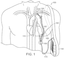
- FIG. 1 illustrates a circulatory support and/or intravascular ventricular assist system 100 configured in accordance with select embodiments of the present technology.
- the system 100 can include an expandable member 110 implantable in an aorta of a patient suffering from heart failure. Expandable member 110 may be referred to as an IABP or balloon.
- the system 100 can further include a first pneumatic driveline 120 (also referred to as an "internal driveline"), an arterial interface device or stopper 130, a second pneumatic driveline 140, a skin interface device 190, a drive unit 150, and sensors 160.
- the system 100 can provide counterpulsation therapy to a patient suffering from heart failure.
- the expandable member 110 can be a balloon or other element that can change size and/or shape in response to being filled with a gas or liquid.
- the expandable member 110 is a balloon composed of a biocompatible, non-thrombogenic elastomeric material (e.g., Biospan ® -S).
- the expandable member 110 can also be made of other suitable materials.
- the expandable member 110 is transitionable between at least a first state in which it is generally deflated and a second state in which it is generally inflated to an effective counterpulsation volume.
- An effective counterpulsation volume may be a volume of fluid that occupies the expandable member 110 after rapidly inflating the expandable member 110 positioned in the patient's aorta immediately after aortic valve closure (dicrotic notch).
- the effective counterpulsation volume within the expandable member 110 increases the diastolic aortic pressure by 25-70%, augmenting end-organ and coronary perfusion.
- the effective counterpulsation volume may be based on a lowest therapeutic diastolic blood pressure for a particular patient, or on an average lowest therapeutic diastolic blood pressure for a patient population.
- the size of the expandable member 110 and/or an air mover 220, 320 of the drive unit 200, 300 ( FIGs.
- an effective counterpulsation volume for a patient may be 50 cc to achieve the lowest therapeutic diastolic blood pressure for the patient, or the average lowest therapeutic diastolic blood pressure for a patient population.
- the expandable member 110 may include a fully inflated volume of greater than 50 cc (e.g., 55 cc), while the air mover 220, 320 may be configured to expel a volume of air that is less than the fully inflated volume of the expandable member 110 (i.e., the lowest therapeutic diastolic blood pressure for the patient, or the average lowest therapeutic diastolic blood pressure for a patient population).
- the "air mover" 220, 320 may include a bellows, a compressed gas cylinder, a pneumatic piston, a diaphragm, a compressor, or other mechanism to deliver the effective counterpulsation volume into the over-sized balloon.
- the bellows includes a pneumatic output in fluid connection with the expandable member 110, a first end (e.g., the static flange 229, 329 of FIGs. 2A , 2B , and 3 ) and a second end (e.g., the dynamic flange 228, 328 of FIGs. 2A , 2B , and 3 ).
- the first end is fixed and the second end is displaceable. While the embodiments of FIGs. 2A , 2B and 3 describe the "air mover" as a bellows 220, 320, the "air mover" is not limited to the bellows configuration and may also include any mechanism to deliver the appropriate gas volume into the expandable member 110.
- Full inflation of the expandable member 110 depends on various parameters of the system 100.
- the expandable member 110 being "fully inflated” may depend on pneumatic system volume, a size or capacity of the expandable member 110, changes in volume of the bellows 220, 320 corresponding to inflation and deflation cycles, and patient blood pressure. With the exception of patient blood pressure, these parameters may be measured or compiled from the system 100 and its components as described in relation to FIG. 1 .
- the blood pressure threshold below which a leak could occur is, therefore, the lowest therapeutic diastolic blood pressure for the patient. Accounting for the volumes of the pneumatic system, expandable member, and the low-end threshold of blood pressure, movement of the bellows 220, 320 is limited to prevent full inflation of the expandable member 110. As described herein, the limitation on the bellows movement may be implemented mechanically or by software instructions.
- the expandable member 110 can provide counterpulsation therapy without risk of expandable member 110 rupture or fluid leak into the patient's vasculature by repeatedly transitioning between the first state (deflation) and the second state (inflation) without exceeding an effective counterpulsation volume.
- the drive unit 150 can direct the effective counterpulsation volume of fluid (gas or liquid, e.g., air) into an internal volume of the expandable member 110 via the first pneumatic driveline 120 and the second pneumatic driveline 140, as described in greater detail below.
- the expandable member 110 can also be sized and/or shaped to reduce and/or prevent the expandable member 110 from blocking arteries branching from the aorta, such as the renal arteries, and to have an internal volume when fully inflated that is less than the effective counterpulsation volume.
- the expandable member 110 may also have certain features generally similar to those described in disclosures incorporated herein by reference.
- the expandable member 110 includes an expandable end effector other than or in addition to a balloon.
- the drive unit 150 can generate gas flow into and out of the expandable member 110 via the first pneumatic driveline 120 and the second pneumatic driveline 140 that converge to form an external pneumatic driveline 172 extending from the drive unit 150.
- the drive unit 150 can generate a positive pressure to accelerate gases into the expandable member 110 via the first pneumatic driveline 120 and the second pneumatic driveline 140, thereby inflating the expandable member 110.
- the drive unit 150 can also induce a negative pressure to withdraw gases from the expandable member 110 via the first pneumatic driveline 120 and the second pneumatic driveline 140, thereby deflating the expandable member 110.
- the drive unit 150 can induce gas flow into and out of the expandable member 110 through a bellows (not depicted in Fig. 1 ).
- the drive unit 150 can control the volume of air being pushed into the expandable member 110 to avoid fully inflating or overinflating the expandable member 110.
- the volume of airflow generated by the bellows e.g., the volume of the bellows
- the volume of fluid expelled by the bellows may be restricted by an air mover limiter (not depicted in Fig.
- the drive unit 150 uses ambient air from the environment surrounding the drive unit 150 (e.g., "room air") to drive operation of the system 100. Using ambient air is expected to reduce the size, weight, and/or cost of the drive unit 150 relative to a drive unit that relies on an internal gas or fluid supply (e.g., helium tanks). For example, in some embodiments the drive unit 150 can weigh about 3 kg or less.
- the driveline can be disconnected near the skin interface device 190 when the system 100 is not being actively used.
- the system 100 may allow chronic support of heart function and blood flow, while still allowing the patient to remain ambulatory.
- Typical ventricular assist devices require femoral access for the driveline and/or connection to large, stationary external control units, and therefore confine the patient to a hospital bed in the supine position for the duration of therapy.
- the system 100 allows the patient to move about relatively unencumbered.
- the therapy level provided by the system 100 can be adjusted to match patient need.
- the effective counterpulsation volume and support ratio e.g., 1:1, 1:2, 1:3 support
- the expandable member 110 can be adjusted for each patient to vary the support provided while still underinflating the expandable member 110 to prevent undue stress and/or gas leakage.
- the support ratio measures the ratio of beats to inflations of the balloon. For example a 1:1 support ratio indicates the for every beat there is a corresponding inflation of the balloon, whereas a 1:2 support ratio indicates that there are two beats before each inflation, and a 1:3 support ratio indicates that there are three beats before each inflation.
- the drive unit 150 can have a user interface (not depicted) where a clinician can control the effective counterpulsation volume or support ratio.
- drive unit 150 can be controlled via other external inputs (e.g., using a corresponding tablet or other device that is in electrical communication with drive unit 150).
- Gradually reducing the effective counterpulsation volume over time e.g., by changing the desired travel of an internal bellows mechanism as a percent of the full travel
- the travel of the internal bellows mechanism may be restricted mechanically and/or by computer instruction via the user interface to limit the inflated volume of the expandable member 110 to below the fully-inflated volume.
- the system 100 can be turned off to, for example, assess the ability of the patient to handle cardiac demand without support before removing the system 100, or for another suitable reason.
- the expandable member 110 is designed to remain in the aorta in a deflated condition for a relatively prolonged duration (e.g., for 23 hours in a single day). This is in direct contrast to conventional devices, which often must be removed if turned off for more than about fifteen minutes because reactivation could result in a shower of emboli that formed when in the inactive state.
- the present disclosure contemplates at least two embodiments of drive unit 150.
- the first embodiment is depicted in FIGs. 2A-B and refers to the drive unit by reference numeral 200.
- the second embodiment is depicted in FIG. 3 and refers to the drive unit by reference numbers 300.
- FIG. 2A depicts a first embodiment of drive unit 200.
- the drive unit 200 may include a bellows 220 and a motor 222 (e.g., an electric motor such as a brushless DC motor.
- the space to the left of bellows 220 in FIG. 2A may be at least partially occupied by electrical components (not illustrated) used to control motor 222.
- Such components may include one or more computer processors and memory containing computer processor readable instructions capable of being executed by the computer processor.
- the same space may be at least partially occupied by mechanical components such as value manifolds (e.g., for coupling bellows output/pneumatic output 223 to an applicable port 204).
- Bellows 220 may be an axial expansion bellows that is able to expand and contract along the A-A axis depicted in Fig. 2A in response to rotation of the motor 222 in different directions.
- the bellows 220 is expanded such that the expandable member 110 ( FIG. 1 ) is deflated.
- the expandable member 110 FIG. 1
- the bellows 220 may have a constant cross-sectional geometry along its length so that the volume within the bellows 220 is varied according to the bellows length.
- the motor 222 may include a rotor 222a and stator 222b.
- the rotor 222a may be joined to a rotary-to-linear transformer.
- the rotor 222a may be joined to a ball nut 224 carrying a ball screw 226 that is affixed to a dynamic flange 228.
- the bellows 220 may be sealed by the dynamic flange 228 at a bellows second end proximal to the ball screw 226 and by a static flange 229 ( FIG. 2A ) at a bellows first end that is distal to the ball screw 226.
- a bellows outlet 233 ( FIG. 2A ) may allow communication of fluid within the external drive line 172 to the expandable member 110 in response to movement or displacement of the bellows second end (i.e., the dynamic flange 228).
- the bellows outlet 233 may be formed within the static flange 229.
- the ball screw 226 in combination with the ball nut 224 may form a mechanical rotary-to-linear transformer that converts rotational motion of the motor 222 to linear motion with little friction. Rotation of the ball nut 224 by the rotor 222a within the stationary stator 222b may cause the ball screw 226 to move linearly along axis A-A and, correspondingly, cause linear movement of the bellows 220.
- the ball screw 226 may be threaded to provide a helical raceway 226a for balls 226b ( FIG. 2C ) of the ball nut 224 and may act as a precision screw.
- Several dimensions may define the ball screw 226 and raceway 226a.
- the ball screw 226 may include a pitch measuring the distance between grooves of the helical raceway 226a.
- the rotor 222a and ball nut 224 assembly may be mounted to a housing 230 of the motor 222 via radial bearings 232.
- the inner race of the radial bearings 232 may be affixed to the rotor 222a and ball nut 224 assembly while the outer race of the radial bearings 232 and the stator 222b may be affixed to a motor housing 230.
- Actuation of the motor 222 may cause rotational movement of the rotor 222a and ball nut 224 which may cause balls 226c ( FIG.
- Movement of the ball screw 226 is translated to the bellows 220 via the dynamic flange 228, causing the bellows 220 to expand or contract to create negative or positive fluid flow, respectively, within the external drive line 172, which is in fluid connection with the expandable member 110 via the bellows outlet 233 ( FIG. 2A ).
- the ball screw 226 may be fixedly mated to the dynamic flange 228 via a threaded interface (as depicted in FIG. 2B ).
- the dynamic flange 228 and ball screw 228 are one continuous piece.
- ball screw 228 may directly and efficiently translate its motion to the bellows (e.g., withdrawal of the ball screw 226 away from the static flange 229 may pull the dynamic flange 228 to expand the bellows 220).
- the ball nut 224 may be configured as an air mover limiter to mechanically restrict contraction of the bellows and positive fluid flow within the external drive line 172 such that the expandable member 110 is inflated to an effective counterpulsation volume, but remains under-inflated.
- the air mover limiter may be a ball nut 224 including a stop pin 224a. The air mover limiter may allow the ball nut 224 to spin while limiting travel of the bellows 220 along the ball screw 226 via the dynamic flange 228 by stopping further linear movement of the air mover limiter 224 along the axis A-A.
- a clutch-like collar 240 inside the air mover limiter 224 prevents the air mover limiter 224 from travelling past the stop pin(s) 224a.
- the stop pin 224a may be placed in a valley or root of the raceway 226a (e.g., by drilling a hole and pressing in the stop pin).
- the stop pin(s) 224a are placed to limit the ball nut 224 from spinning along the ball screw 226 to under-inflate the expandable member 110.
- the air mover limiter 224 disengages from the raceway and begins to idle.
- the air mover limiter may include other mechanical means to limit the travel of the bellows 220 or to otherwise restrict inflation of the expandable member to less than a fully-inflated volume.
- drive unit 200 may include processor 402, memory 404, and drive unit 402.
- Processor 402 may include one or more dedicated or non-dedicated micro-processors, micro-controllers, sequencers, micro-sequencers, digital signal processors, processing engines, hardware accelerators, applications specific circuits (ASICs), state machines, programmable logic arrays, any integrated circuit(s), discrete circuit(s), etc. that is/are capable of processing data or information, or any suitable combination(s) thereof.
- Memory 404 may include any suitable non-volatile memory device, chip, or storage device capable such as one or more of: system memory, frame buffer memory, flash memory, random access memory (RAM), read only memory (ROM), a register, and a latch.
- Processor 402 is capable of executing executable instructions (e.g., as stored in memory 404).
- Processor 402 may be configured to control motor 222, and by extension, the bellows 220.
- an encoder disk 234 and encoder sensor 236 may determine the angular position, speed, and/or direction of the rotor and provide such information as positional feedback signal(s) to a processor 402 and/or memory 404.
- the encoder disk 234 is a component of an encoder which includes the encoder sensor 236. In combination with the encoder sensor 236, the encoder disk 234 converts mechanical motion into electrical signals.
- Encoder disks are typically made of metal, plastic, glass, or paper, and they have a series of segments.
- the encoder sensor 236 is able to differentiate between the segments to determine disk rotation. In some embodiments, the segments are clear and opaque, magnetic and non-magnetic, white and black, or any other series of alternating materials or appearances. Rotation of the disk 234 through the sensor 236 creates a series of electrical pulses that can be used to measure the speed, position, or direction of the encoder disk's rotation and, thus, the motor 222 rotation.
- the encoder disk 234 may also include a "home" position.
- the home position of an encoder disk is the position where the encoder is pointing to the "zero value" or default position of the encoder when it is turned on or reset.
- Incremental encoder disks determine the home position by detecting the start of a pattern on the disk. For example, the disk 234 might have a pattern of alternating black and white lines. The encoder would start counting when it detects the first black line.
- Absolute encoder disks may determine the home position by reading a code value on the disk. For example, the disk might have a code that represents the number 0.
- Processor 402 and/or memory 404 may receive the code from the sensor 236, 336 ( FIGs.
- the encoder sensor 236 may read the code and then set the encoder disk 234 position to 0.
- the home position can be important for a variety of reasons, such as measuring rotation of the ball screw 228 and translation of that movement into a volume of gas within or expelled by the bellows 220, or alignment of the encoder with another device.
- the processor 402 may execute instructions to return the encoder disk 234 to that position when it is turned off or reset. This ensures that the encoder is always in the correct position.
- a linear position sensor may be used to determine the position of the ball screw 226 or bellows 220 and to provide such positional feedback signal(s).
- Processor 402 and/or memory 404 may also receive control information from drive unit UI 406 and provide display information (e.g., status information) to drive unit UI 406.
- processor 402 and/or memory 404 may similarly receive EKG signal(s) from skin interface device 190 and one or more sensors 160 ( FIG. 1 ), one or more external control signals (e.g., from a tablet or other computing device (not depicted)), and one or more sensor signals.
- processor 402 and/or memory 404 may receive a pressure signal as observed by a pressure sensor (not depicted) located in proximity to balloon 110 when disposed in an artery (e.g., the descending aorta, as depicted in FIG. 1 ) of a patient undergoing therapy (e.g., counterpulsation therapy).
- the one or more pressure signals may be, indicative of the pressure exerted on balloon 110 in such artery and/or the pressure within such artery.
- Processor 402 may use one or more of the positional feedback signals, drive unit UI 406 control signals, EKG signals, external control signals, and sensor signals to control motor 222.
- EKG signals may be used to ensure proper timing of the inflation and/or deflation of the balloon 110 (e.g., to pursue counterpulsation).
- drive unit UI 406 control signal and external control signals may be used to change the effective counterpulsation volume, support ratio, and maximum inflation volume as discussed supra.
- the various signals described above could be monitored to determine when the patient's blood pressure falls below the lowest therapeutic diastolic blood pressure for the patient, or the average lowest therapeutic diastolic blood pressure for a patient population. This determination would signal full or over-inflation of the expandable member 110 and be used to further adjust the bellows travel to below the previously-determined volume to keep the expandable member under-inflated.
- the contour of the bellows pressure during inflation dwell or the patient's blood pressure during the partial cycle, or some combination of these measurements may also be used to signal full or over-inflation.
- under-inflation of the expandable member 110 may be useful to detect ruptures in the expandable member 110.
- blood may enter the pneumatic system through a crack or rift in the expandable member 110 that may develop due to high cycle fatigue and grow steadily in size over time with continued use. Blood escaping through the crack or rift becomes visible in the pneumatic driveline. Under-inflation allows blood to ingress, but air cannot egress when the rift is small. Observation of blood in the driveline will signal the need to discontinue support.
- Other embodiments may employ linear brushless DC motors, solenoids, and/or piezo electric actuators to compress and expand bellows 220.
- Drive unit 200 may be used to effectively inflate and deflate the inflatable member 110 using ambient air to provide counterpulsation therapy in patients with heart failure.
- the following component values set forth in the table below are exemplary for such purposes for counterpulsation using the drive unit 200 and an approximately 20-60cc balloon as the inflatable member 110.
- Drive Unit 200 Component (units) Dimensions Bellows Outside Diameter (mm) 90 Bellows Piston Area (cm 2 ) 48.2 Bellows Travel (mm) 17.7 Drive Unit Height (mm) 87 Envelope Volume / Size of Bellows Plus Drivetrain (cc) 557
- drive unit 200 uses a significant amount of power merely to overcome the rotational inertia of rotor 222a and may not be "fast enough" to treat patients with heart arrhythmias, irregular heartbeats, or a-fib.
- Ball screws pitch may be selected or adjusted to improve efficiency of the drive unit.
- adjusting the ball screw pitch (and/or adjusting the diameter of the bellows 220) may better match the impedance of the motor 222 and the impedance of the pneumatic load on the drive unit 200 (e.g., the collectively pneumatic load of balloon 110, first pneumatic driveline 120, second pneumatic driveline140, and external driveline 172).
- Such an improvement in efficiency may improve the battery life of any battery employed to drive motor 222.
- a second embodiment of the drive unit 300 may include a bellows 320 and a motor 322 (e.g., an electric motor such as a brushless DC motor).
- Bellows 320 may be an axial expansion bellows that is able to expand and contract along the B-B axis depicted in Fig. 3 in response to rotation of the motor 322 in different directions.
- the bellows 320 may include a dynamic flange 328.
- the dynamic flange 328 may be sized and shaped to receive or house at least a portion of the motor 322 such that at least a portion of the motor 322 is nested within a bellows cavity 320a.
- the direction of the recess 328a may be toward the bellows cavity 320 and take a three-dimensional shape (e.g., a cylinder) suitable for receiving or housing and nesting at least a portion of the motor 322 within the bellows cavity 321a while maintaining sufficient stroke length to provide effective air flow within the external drive line 172.
- the recess 328a may allow a reduction in size and weight of the outer case 302, improving mobility of the system (e.g., as compared to the size of outer case 202).
- the bellows 320 is depicted in an expanded or uncompressed state such that the expandable member 110 ( FIG. 1 ) is deflated.
- the motor 322 includes a rotor 322a and stator 322b.
- the rotor 322a may be shaped to join a rotary-to-linear transformer, for example, a ball nut 324 carrying a ball screw 326 that is affixed to a dynamic flange 328 via a threaded interface.
- the rotor 323 and the ball nut 324 may be formed as a single piece.
- the ball screw 326 is hollow to reduce weight.
- the rotor 323 and ball nut 324 assembly may be mounted to a housing of the motor 332 via radial bearings 330.
- the inner race of the radial bearings 330 may be affixed to the rotor 323 and ball nut 324 assembly while the outer race of the radial bearings 330 and the stator 323b may be affixed to a motor housing 332.
- actuation of the motor 322 may cause rotational movement of the rotor 323 and ball nut 324 which may translate into linear movement of the ball screw 326 along axis B-B.
- Movement of the ball screw 326 may be translated to the bellows 320 via the dynamic flange 328, causing the bellows 320 to expand or contract to create negative or positive fluid flow, respectively, within the external drive line 172, which is in fluid connection with the expandable member 110 via a bellows output/pneumatic output 333 associated with the static flange 329.
- Other embodiments may employ linear brushless DC motors, solenoids, and/or piezo electric actuators to compress and expand bellows 320.
- the ball screw 326 may be mated to the dynamic flange 328 (or the two components may be one continuous piece) to allow the ball screw 328 to directly and efficiently translate its motion to the bellows 320 while the rotor 322a and ball nut 324 spin within the stator 322b around axis B-B. Rotation of the rotor 322a may carry the balls of the ball nut 324 within the helical raceway 226a of the ball screw 226, thus causing movement of the ball screw 226 along axis B-B.
- the ball nut 324 may be configured as an air mover limiter 224, as described in relation to FIGs. 2C-2D to restrict movement or displacement of the dynamic flange 328 and positive fluid flow within the external drive line 172 such that the expandable member 110 is inflated to an effective counterpulsation volume, but remains under-inflated.
- an encoder disk 334 and encoder sensor 336 may determine the angular position, speed, and/or direction of the rotor and provide such information to a processor via electrical feedback signals (not depicted).
- the encoder disk 334 is a component of an encoder which includes the encoder sensor 336 and includes the same advantages described above in relation to encoder disk 234 and encoder sensor 236.
- a linear position sensor (not depicted) may be used to determine the position of the ball screw 326 or bellows 320 and to provide that information to such processor.
- Such a processor may also receive EKG signals from skin interface device 190 and one or more sensors 160 ( FIG.
- suitable external control signals e.g., from a tablet (not depicted) configured to control motor 322 and the travel of bellows 220, a user interface operatively coupled to the case 302 (not depicted), etc.
- sensors e.g., pressure sensors (not depicted) capable of sensing the pressure in the descending aorta).
- Drive unit 300 may be used to effectively inflate and deflate inflatable member 110 using ambient air to provide counterpulsation therapy in patients with heart failure, including patients with heart arrhythmias, irregular heartbeats, or a-fib.
- the following ranges of component values may be efficient and/or economical for counterpulsation using drive unit 300 and an approximately 20-60cc balloon as inflatable member 110.
- drive unit 200, 300 may include processor 402, memory 404, and drive unit 402.
- Encoder disk 234, 334 and encoder sensor 236, 336 may determine the angular position, speed, and/or direction of the rotor and provide such information as positional feedback signal(s) to a processor 402 and/or memory 404.
- a linear position sensor (not depicted) may be used to determine the position of the ball screw 226, 326 or bellows 220, 320 and to provide such positional feedback signal(s).
- Processor 402 and/or memory 404 may also receive control information from drive unit UI 406 and provide display information (e.g., status information) to drive unit UI 406.
- processor 402 and/or memory 404 may similarly receive EKG signal(s) from skin interface device 190 and one or more sensors 160 ( FIG. 1 ), one or more external control signals (e.g., from a tablet or other computing device (not depicted)), and one or more sensor signals.
- processor 402 and/or memory 404 may receive a pressure signal as observed by a pressure sensor (not depicted) located in proximity to balloon 110 when disposed in an artery (e.g., the descending aorta, as depicted in FIG. 1 ) of a patient undergoing therapy (e.g., counterpulsation therapy).
- the one or more pressure signals may be, indicative of the pressure exerted on balloon 110 in such artery and/or the pressure within such artery.
- Processor 402 may use one or more of the positional feedback signals, drive unit UI 406 control signals, EKG signals, external control signals, and sensor signals to control motor.
- EKG signals may be used to ensure proper timing of the inflation and/or deflation of the balloon 110 (e.g., to pursue counterpulsation).
- drive unit UI 406 control signal and external control signals may be used to change the effective counterpulsation volume, support ratio, and maximum inflation volume, as discussed supra.
- FIG. 5 is a flowchart of a software restriction including processor-executable instructions for method 500 for initializing the drive unit 200, 300 for counterpulsation support to achieve the lowest therapeutic diastolic blood pressure for the patient, or the average lowest therapeutic diastolic blood pressure for a patient population.
- Each step of the method 500 is one or more processor-executable instructions performed on a microprocessor or other computing device (e.g., drive unit 200, 300 including processor 402 and memory 404) which may be physically configured to execute the different aspects of the method.
- Each step may include execution of any of the instructions as described in relation to the drive unit 200, 300. While the below blocks are presented as an ordered set, the various steps described may be executed in any particular order to complete the air mover limiter methods described herein.
- the processor 402 may execute a "power on” or “startup” command.
- processor-executable instructions stored in the memory 404 may cause the processor 402 to begin an initialization sequence for the drive unit 200, 300.
- the processor may execute a "gas block” command so that no gas is pushed into the bellows 220, 320 during execution of the method 500.
- block 503 may include the processor executing a command to configure (i.e., open or close) one or more valves in the system 100 so that no gas is pushed into the bellows 220, 320.
- the processor 402 may execute a "move bellows" command.
- Processor-executable instructions stored in the memory 404 may cause the processor 402 to apply power to the motor 222, 322 causing the bellows 220, 320. For example, a dynamic flange 228, 328, may begin movement toward a static flange 229, 329.
- the processor 402 may execute a "check motor current" command.
- processor-executable instructions stored in the memory 404 may cause the processor 402 to determine an electric current of the motor 222, 322. If the current is steady (i.e., does not rise beyond a threshold rate over time) or does not increase beyond a threshold amount, then the method 500 may return to block 504 and continue bellows movement.
- the method 500 may proceed to block 508.
- the processor 402 may execute a "bellows return" command.
- the distance of this return move may be a constant stored in memory.
- processor-executable instructions stored in the memory 404 may cause the processor 402 to reverse the motor 222, 322 to a "home” position based on reading pulses from the encoder disk 234, 334.
- the distance between full compression and "home” also corresponds to the effective counterpulsation volume, as described herein.
- the pneumatic valves are closed in preparation for counterpulsation pumping to support the patient.
- drive unit 300 may have several advantages over drive unit 200.
- drive unit 300 can be configured to be smaller and lighter (i.e., have a smaller volume enclosure) than drive unit 200, which can have a significant impact on the ability of a person having to carry drive unit 150 to be mobile/engage in more ambulatory behavior.
- bellows 320 can have a smaller bellows travel distance (and a shorter ball screw) than drive unit 220.
- the impedance of the pneumatic load on the drive unit e.g., the collectively pneumatic load of balloon 110, first pneumatic driveline 120, second pneumatic driveline140, and external driveline 172
- the impedance of the motor i.e., the mechanical subsystem of drive unit
- the power consumption necessary to inflate and deflate is reduced, thereby increasing efficiency of drive unit 300 as compared to drive unit 200.
- the overall dimension of drive unit 300 along its axis of linear motion (i.e., axis B-B) can be smaller than the overall dimension of drive unit 200 along its axis of linear motion (i.e., axis B-B).
- the longest dimension of drive unit 200 may be the along its axis of linear motion (i.e., axis B-B)
- the longest dimension of drive unit 300 may be orthogonal to its axis of linear motion (i.e., orthogonal to axis B-B).
- outer cases 202 and 302 are both a cuboid (or substantially in the shape of a cuboid) and are configured such that the face of static flange 229, 329 is parallel to a face of outer case 202, 302.
- the longest dimension of drive unit 300 may correspond to an axis that is parallel to the diameter of bellows 320.
- drive unit 300 may be configured to operate fast enough to deflate a corresponding balloon or inflatable member 110 by 50% within approximately 100ms of the R-wave in the QRS complex, so that it may be capable of treating patients with irregular heartbeats (e.g., patients with atrial fibrillation or "a-fib").
- a-fib is an irregular and/or rapid heart rate that occurs when the two upper chambers of the heart experience chaotic electrical signals. The result is a fast and irregular heart rhythm that is difficult to predict for effective inflation and deflation of the expandable member 110.
- the expandable member 110 should be deflated by at least 50% within approximately 100-120ms of the R wave.
- the expandable member 110 might obstruct blood flow within the aorta and increase the workload of the heart.
- Using the R-wave in a QRS complex as an indicator of ventricle contraction requires processing of an EKG signal to locate the R-wave, which can consume about 20-50ms, depending on the algorithm employed using conventional algorithms and processors.
- drive unit 300 may be capable of effectively treating patients with irregular heartbeats and a-fib.
- drive unit 300 can be far more efficient than drive unit 200 in terms of power consumption thereby prolonging battery life of the battery (not depicted) powering motor 322 as compared to battery (not depicted) powering motor 222, assuming the same such batteries are the same.
- motor 222 may inefficiently use a disproportional amount of power to overcome the rotational inertia of the rotor 222a in drive unit 200 as compared to the amount of power utilized in drive unit 300 to overcome the rotational inertia of rotor 322a.
- Drive unit 300 realizes this advantage by (a) setting the ball screw pitch in drive unit 300 such that the impedance of the motor 322 is the same or substantially the same (i.e., matched or substantially matched) to the impedance of the pneumatic load on the drive unit 300, and/or (b) using an enlarged bellows 320, which permits a design with a reduced bellows travel (and which may further help match or substantially match impedance of the motor 322 to the pneumatic load on the drive unit 300).
- drive unit 200 and drive unit 300 are merely exemplary. Drive units with different component values are contemplated as being within the scope of this disclosure.
- the words “comprise,” “comprising,” and the like are to be construed in an inclusive sense, as opposed to an exclusive or exhaustive sense; that is to say, in the sense of "including, but not limited to.”
- the terms “connected,” “coupled,” or any variant thereof means any connection or coupling, either direct or indirect, between two or more elements; the coupling of connection between the elements can be physical, logical, or a combination thereof.
- the words “herein,” “above,” “below,” and words of similar import, when used in this application, shall refer to this application as a whole and not to any particular portions of this application.
Landscapes
- Health & Medical Sciences (AREA)
- Engineering & Computer Science (AREA)
- Heart & Thoracic Surgery (AREA)
- Cardiology (AREA)
- Life Sciences & Earth Sciences (AREA)
- Public Health (AREA)
- Biomedical Technology (AREA)
- Hematology (AREA)
- Mechanical Engineering (AREA)
- Animal Behavior & Ethology (AREA)
- General Health & Medical Sciences (AREA)
- Anesthesiology (AREA)
- Veterinary Medicine (AREA)
- Vascular Medicine (AREA)
- Medical Informatics (AREA)
- Transplantation (AREA)
- Physics & Mathematics (AREA)
- Geometry (AREA)
- External Artificial Organs (AREA)
Applications Claiming Priority (1)
| Application Number | Priority Date | Filing Date | Title |
|---|---|---|---|
| US18/199,671 US20240382739A1 (en) | 2023-05-19 | 2023-05-19 | System and method for preventing gas leakage from an intra-aortic balloon |
Publications (1)
| Publication Number | Publication Date |
|---|---|
| EP4464364A1 true EP4464364A1 (fr) | 2024-11-20 |
Family
ID=91184862
Family Applications (1)
| Application Number | Title | Priority Date | Filing Date |
|---|---|---|---|
| EP24176739.1A Pending EP4464364A1 (fr) | 2023-05-19 | 2024-05-17 | Système et procédé pour empêcher une fuite de gaz à partir d'un ballonnet intra-aortique |
Country Status (4)
| Country | Link |
|---|---|
| US (1) | US20240382739A1 (fr) |
| EP (1) | EP4464364A1 (fr) |
| JP (1) | JP2024167093A (fr) |
| CA (1) | CA3238596A1 (fr) |
Cited By (1)
| Publication number | Priority date | Publication date | Assignee | Title |
|---|---|---|---|---|
| CN121117576A (zh) * | 2025-11-12 | 2025-12-12 | 南京诺令生物科技有限公司 | Iabp安全盘膜片泄漏检测方法、装置、设备及介质 |
Citations (15)
| Publication number | Priority date | Publication date | Assignee | Title |
|---|---|---|---|---|
| US3266487A (en) | 1963-06-04 | 1966-08-16 | Sundstrand Corp | Heart pump augmentation system and apparatus |
| US3720199A (en) | 1971-05-14 | 1973-03-13 | Avco Corp | Safety connector for balloon pump |
| WO1980002366A1 (fr) * | 1979-05-07 | 1980-11-13 | H Krause | Methode et appareil de pompage de sang dans un recipient |
| US4522194A (en) | 1983-02-18 | 1985-06-11 | Baylor College Of Medicine | Method and an apparatus for intra-aortic balloon monitoring and leak detection |
| US5169379A (en) * | 1989-06-14 | 1992-12-08 | L-Vad Technology | In-series ventricular assist system and method of controlling same |
| US5242374A (en) | 1991-03-29 | 1993-09-07 | Aisin Seiki Kabushiki Kaisha | Leak detector for an intra-aortic balloon pump |
| US5513956A (en) | 1994-01-14 | 1996-05-07 | Arrow International Investment Corp. | Circulatory assisted device with motor driven gas pump |
| US5817001A (en) | 1997-05-27 | 1998-10-06 | Datascope Investment Corp. | Method and apparatus for driving an intra-aortic balloon pump |
| US6536260B2 (en) | 1999-06-24 | 2003-03-25 | Datascope Investment Corp. | Balloon catheter leak detection method and apparatus |
| US6735532B2 (en) | 1998-09-30 | 2004-05-11 | L. Vad Technology, Inc. | Cardiovascular support control system |
| US7892162B1 (en) | 2009-10-22 | 2011-02-22 | Valluvan Jeevanandam | Arterial interface |
| US8066628B1 (en) | 2010-10-22 | 2011-11-29 | Nupulse, Inc. | Intra-aortic balloon pump and driver |
| US20200038566A1 (en) * | 2017-01-12 | 2020-02-06 | The Regents Of The University Of California | Endovascular perfusion augmentation for critical care |
| US20210177425A1 (en) * | 2017-10-24 | 2021-06-17 | Tufts Medical Center, Inc. | Systems and methods for selectively occluding the superior vena cava for treating heart conditions |
| WO2023014659A1 (fr) * | 2021-08-02 | 2023-02-09 | Nupulsecv, Inc. | Unité d'entraînement pour systèmes de support circulatoire intravasculaire |
Family Cites Families (3)
| Publication number | Priority date | Publication date | Assignee | Title |
|---|---|---|---|---|
| WO2004112868A1 (fr) * | 2003-06-20 | 2004-12-29 | Tohoku Electronic Industrial Co., Ltd. | Dispositif artificiel de muscle cardiaque |
| US20060052659A1 (en) * | 2004-09-07 | 2006-03-09 | Topaz Stephen R | Cardiac device and method |
| AU2020386557A1 (en) * | 2019-11-22 | 2022-05-26 | Tufts Medical Center, Inc. | Systems and methods for selectively occluding the superior vena cava for treating heart conditions |
-
2023
- 2023-05-19 US US18/199,671 patent/US20240382739A1/en active Pending
-
2024
- 2024-05-15 CA CA3238596A patent/CA3238596A1/en active Pending
- 2024-05-17 JP JP2024081210A patent/JP2024167093A/ja active Pending
- 2024-05-17 EP EP24176739.1A patent/EP4464364A1/fr active Pending
Patent Citations (15)
| Publication number | Priority date | Publication date | Assignee | Title |
|---|---|---|---|---|
| US3266487A (en) | 1963-06-04 | 1966-08-16 | Sundstrand Corp | Heart pump augmentation system and apparatus |
| US3720199A (en) | 1971-05-14 | 1973-03-13 | Avco Corp | Safety connector for balloon pump |
| WO1980002366A1 (fr) * | 1979-05-07 | 1980-11-13 | H Krause | Methode et appareil de pompage de sang dans un recipient |
| US4522194A (en) | 1983-02-18 | 1985-06-11 | Baylor College Of Medicine | Method and an apparatus for intra-aortic balloon monitoring and leak detection |
| US5169379A (en) * | 1989-06-14 | 1992-12-08 | L-Vad Technology | In-series ventricular assist system and method of controlling same |
| US5242374A (en) | 1991-03-29 | 1993-09-07 | Aisin Seiki Kabushiki Kaisha | Leak detector for an intra-aortic balloon pump |
| US5513956A (en) | 1994-01-14 | 1996-05-07 | Arrow International Investment Corp. | Circulatory assisted device with motor driven gas pump |
| US5817001A (en) | 1997-05-27 | 1998-10-06 | Datascope Investment Corp. | Method and apparatus for driving an intra-aortic balloon pump |
| US6735532B2 (en) | 1998-09-30 | 2004-05-11 | L. Vad Technology, Inc. | Cardiovascular support control system |
| US6536260B2 (en) | 1999-06-24 | 2003-03-25 | Datascope Investment Corp. | Balloon catheter leak detection method and apparatus |
| US7892162B1 (en) | 2009-10-22 | 2011-02-22 | Valluvan Jeevanandam | Arterial interface |
| US8066628B1 (en) | 2010-10-22 | 2011-11-29 | Nupulse, Inc. | Intra-aortic balloon pump and driver |
| US20200038566A1 (en) * | 2017-01-12 | 2020-02-06 | The Regents Of The University Of California | Endovascular perfusion augmentation for critical care |
| US20210177425A1 (en) * | 2017-10-24 | 2021-06-17 | Tufts Medical Center, Inc. | Systems and methods for selectively occluding the superior vena cava for treating heart conditions |
| WO2023014659A1 (fr) * | 2021-08-02 | 2023-02-09 | Nupulsecv, Inc. | Unité d'entraînement pour systèmes de support circulatoire intravasculaire |
Cited By (1)
| Publication number | Priority date | Publication date | Assignee | Title |
|---|---|---|---|---|
| CN121117576A (zh) * | 2025-11-12 | 2025-12-12 | 南京诺令生物科技有限公司 | Iabp安全盘膜片泄漏检测方法、装置、设备及介质 |
Also Published As
| Publication number | Publication date |
|---|---|
| US20240382739A1 (en) | 2024-11-21 |
| JP2024167093A (ja) | 2024-11-29 |
| CA3238596A1 (en) | 2025-06-20 |
Similar Documents
| Publication | Publication Date | Title |
|---|---|---|
| EP1061967B1 (fr) | Systeme de controle de la pression pour dispositif d'assistance cardiaque | |
| US5713954A (en) | Extra cardiac ventricular assist device | |
| KR101704412B1 (ko) | 대동맥 내 풍선 펌프 및 구동체 | |
| US6669624B2 (en) | Temporary heart-assist system | |
| CN102107030B (zh) | 心脏搏动辅助装置、心脏搏动辅助系统、以及治疗心力衰竭的方法 | |
| JP2008207018A (ja) | 心臓補助デバイス | |
| CA2634816A1 (fr) | Dispositif d'assistance de la circulation sanguine | |
| WO2011100180A1 (fr) | Activation ventriculaire différentielle extracardiaque par le biais de séparations par inertie et barique | |
| EP4464364A1 (fr) | Système et procédé pour empêcher une fuite de gaz à partir d'un ballonnet intra-aortique | |
| US5513956A (en) | Circulatory assisted device with motor driven gas pump | |
| JP2025160489A (ja) | 血管内循環支持システム用の駆動ユニット | |
| WO2025072858A1 (fr) | Dispositifs, systèmes et procédés d'assistance cardiaque | |
| CN107847650B (zh) | 用于控制生物机械心室-主动脉匹配的设备 | |
| US12594414B2 (en) | Heart support and massage machine | |
| US20250387614A1 (en) | Systems, apparatuses, devices and methods of leak detection for pneumatic cardiac assist devices | |
| CN118698020B (zh) | 一种具有体外呼吸腔的主动脉外反搏器械 | |
| CN115175728A (zh) | 肺静脉防护物及其使用方法 | |
| EP4491211A1 (fr) | Détection en temps réel d'ondes r et procédés associés | |
| HK40082458A (en) | Pulmonary vein shield and methods of use | |
| JPS6344385B2 (fr) | ||
| HK1174578B (en) | Intra-aortic balloon pump and driver |
Legal Events
| Date | Code | Title | Description |
|---|---|---|---|
| PUAI | Public reference made under article 153(3) epc to a published international application that has entered the european phase |
Free format text: ORIGINAL CODE: 0009012 |
|
| STAA | Information on the status of an ep patent application or granted ep patent |
Free format text: STATUS: THE APPLICATION HAS BEEN PUBLISHED |
|
| AK | Designated contracting states |
Kind code of ref document: A1 Designated state(s): AL AT BE BG CH CY CZ DE DK EE ES FI FR GB GR HR HU IE IS IT LI LT LU LV MC ME MK MT NL NO PL PT RO RS SE SI SK SM TR |
|
| STAA | Information on the status of an ep patent application or granted ep patent |
Free format text: STATUS: REQUEST FOR EXAMINATION WAS MADE |
|
| 17P | Request for examination filed |
Effective date: 20250520 |