EP4464401A1 - Nitrox-mischungen-herstellmaschine und zugehöriges betriebsverfahren - Google Patents
Nitrox-mischungen-herstellmaschine und zugehöriges betriebsverfahren Download PDFInfo
- Publication number
- EP4464401A1 EP4464401A1 EP24163616.6A EP24163616A EP4464401A1 EP 4464401 A1 EP4464401 A1 EP 4464401A1 EP 24163616 A EP24163616 A EP 24163616A EP 4464401 A1 EP4464401 A1 EP 4464401A1
- Authority
- EP
- European Patent Office
- Prior art keywords
- nitrox
- pressure
- air
- production machine
- molecular separator
- Prior art date
- Legal status (The legal status is an assumption and is not a legal conclusion. Google has not performed a legal analysis and makes no representation as to the accuracy of the status listed.)
- Pending
Links
- 239000000203 mixture Substances 0.000 title claims abstract description 133
- 238000004519 manufacturing process Methods 0.000 title claims abstract description 49
- 238000011017 operating method Methods 0.000 title claims description 12
- QVGXLLKOCUKJST-UHFFFAOYSA-N atomic oxygen Chemical compound [O] QVGXLLKOCUKJST-UHFFFAOYSA-N 0.000 claims abstract description 98
- 239000001301 oxygen Substances 0.000 claims abstract description 98
- 229910052760 oxygen Inorganic materials 0.000 claims abstract description 98
- RLBIQVVOMOPOHC-UHFFFAOYSA-N parathion-methyl Chemical compound COP(=S)(OC)OC1=CC=C([N+]([O-])=O)C=C1 RLBIQVVOMOPOHC-UHFFFAOYSA-N 0.000 claims abstract description 81
- 238000002156 mixing Methods 0.000 claims abstract description 33
- 239000008246 gaseous mixture Substances 0.000 claims description 35
- 239000003638 chemical reducing agent Substances 0.000 claims description 22
- 239000007789 gas Substances 0.000 claims description 15
- 238000011144 upstream manufacturing Methods 0.000 claims description 14
- 230000009189 diving Effects 0.000 claims description 12
- 238000012544 monitoring process Methods 0.000 claims description 10
- 238000005086 pumping Methods 0.000 description 30
- IJGRMHOSHXDMSA-UHFFFAOYSA-N Atomic nitrogen Chemical compound N#N IJGRMHOSHXDMSA-UHFFFAOYSA-N 0.000 description 22
- 238000010438 heat treatment Methods 0.000 description 13
- XLYOFNOQVPJJNP-UHFFFAOYSA-N water Substances O XLYOFNOQVPJJNP-UHFFFAOYSA-N 0.000 description 12
- 229910001868 water Inorganic materials 0.000 description 12
- 229910052757 nitrogen Inorganic materials 0.000 description 11
- 238000001914 filtration Methods 0.000 description 10
- 239000012528 membrane Substances 0.000 description 9
- 230000029058 respiratory gaseous exchange Effects 0.000 description 9
- 238000001035 drying Methods 0.000 description 7
- 239000007788 liquid Substances 0.000 description 7
- OKTJSMMVPCPJKN-UHFFFAOYSA-N Carbon Chemical compound [C] OKTJSMMVPCPJKN-UHFFFAOYSA-N 0.000 description 4
- CURLTUGMZLYLDI-UHFFFAOYSA-N Carbon dioxide Chemical compound O=C=O CURLTUGMZLYLDI-UHFFFAOYSA-N 0.000 description 4
- 238000010521 absorption reaction Methods 0.000 description 2
- 230000006399 behavior Effects 0.000 description 2
- 229910002092 carbon dioxide Inorganic materials 0.000 description 2
- 239000001569 carbon dioxide Substances 0.000 description 2
- UBAZGMLMVVQSCD-UHFFFAOYSA-N carbon dioxide;molecular oxygen Chemical compound O=O.O=C=O UBAZGMLMVVQSCD-UHFFFAOYSA-N 0.000 description 2
- 239000002131 composite material Substances 0.000 description 2
- 239000000356 contaminant Substances 0.000 description 2
- 230000001276 controlling effect Effects 0.000 description 2
- 230000001419 dependent effect Effects 0.000 description 2
- 238000006073 displacement reaction Methods 0.000 description 2
- 239000000428 dust Substances 0.000 description 2
- 239000000835 fiber Substances 0.000 description 2
- 239000012535 impurity Substances 0.000 description 2
- 239000007769 metal material Substances 0.000 description 2
- VUZPPFZMUPKLLV-UHFFFAOYSA-N methane;hydrate Chemical compound C.O VUZPPFZMUPKLLV-UHFFFAOYSA-N 0.000 description 2
- 230000001105 regulatory effect Effects 0.000 description 2
- 230000000284 resting effect Effects 0.000 description 2
- 230000001052 transient effect Effects 0.000 description 2
- 238000004458 analytical method Methods 0.000 description 1
- 230000005540 biological transmission Effects 0.000 description 1
- 238000002485 combustion reaction Methods 0.000 description 1
- 230000008878 coupling Effects 0.000 description 1
- 238000010168 coupling process Methods 0.000 description 1
- 238000005859 coupling reaction Methods 0.000 description 1
- 238000010586 diagram Methods 0.000 description 1
- 238000007599 discharging Methods 0.000 description 1
- 230000007613 environmental effect Effects 0.000 description 1
- 238000011049 filling Methods 0.000 description 1
- 239000000463 material Substances 0.000 description 1
- 238000000034 method Methods 0.000 description 1
- 238000012986 modification Methods 0.000 description 1
- 230000004048 modification Effects 0.000 description 1
- DOTMOQHOJINYBL-UHFFFAOYSA-N molecular nitrogen;molecular oxygen Chemical compound N#N.O=O DOTMOQHOJINYBL-UHFFFAOYSA-N 0.000 description 1
- 238000009304 pastoral farming Methods 0.000 description 1
- 238000012360 testing method Methods 0.000 description 1
- 238000012795 verification Methods 0.000 description 1
Images


Classifications
-
- F—MECHANICAL ENGINEERING; LIGHTING; HEATING; WEAPONS; BLASTING
- F17—STORING OR DISTRIBUTING GASES OR LIQUIDS
- F17C—VESSELS FOR CONTAINING OR STORING COMPRESSED, LIQUEFIED OR SOLIDIFIED GASES; FIXED-CAPACITY GAS-HOLDERS; FILLING VESSELS WITH, OR DISCHARGING FROM VESSELS, COMPRESSED, LIQUEFIED, OR SOLIDIFIED GASES
- F17C5/00—Methods or apparatus for filling containers with liquefied, solidified, or compressed gases under pressures
- F17C5/002—Automated filling apparatus
- F17C5/007—Automated filling apparatus for individual gas tanks or containers, e.g. in vehicles
-
- C—CHEMISTRY; METALLURGY
- C01—INORGANIC CHEMISTRY
- C01B—NON-METALLIC ELEMENTS; COMPOUNDS THEREOF; METALLOIDS OR COMPOUNDS THEREOF NOT COVERED BY SUBCLASS C01C
- C01B21/00—Nitrogen; Compounds thereof
- C01B21/04—Purification or separation of nitrogen
-
- B—PERFORMING OPERATIONS; TRANSPORTING
- B01—PHYSICAL OR CHEMICAL PROCESSES OR APPARATUS IN GENERAL
- B01D—SEPARATION
- B01D53/00—Separation of gases or vapours; Recovering vapours of volatile solvents from gases; Chemical or biological purification of waste gases, e.g. engine exhaust gases, smoke, fumes, flue gases, aerosols
- B01D53/22—Separation of gases or vapours; Recovering vapours of volatile solvents from gases; Chemical or biological purification of waste gases, e.g. engine exhaust gases, smoke, fumes, flue gases, aerosols by diffusion
-
- B—PERFORMING OPERATIONS; TRANSPORTING
- B01—PHYSICAL OR CHEMICAL PROCESSES OR APPARATUS IN GENERAL
- B01D—SEPARATION
- B01D63/00—Apparatus in general for separation processes using semi-permeable membranes
- B01D63/02—Hollow fibre modules
-
- F—MECHANICAL ENGINEERING; LIGHTING; HEATING; WEAPONS; BLASTING
- F17—STORING OR DISTRIBUTING GASES OR LIQUIDS
- F17C—VESSELS FOR CONTAINING OR STORING COMPRESSED, LIQUEFIED OR SOLIDIFIED GASES; FIXED-CAPACITY GAS-HOLDERS; FILLING VESSELS WITH, OR DISCHARGING FROM VESSELS, COMPRESSED, LIQUEFIED, OR SOLIDIFIED GASES
- F17C5/00—Methods or apparatus for filling containers with liquefied, solidified, or compressed gases under pressures
- F17C5/06—Methods or apparatus for filling containers with liquefied, solidified, or compressed gases under pressures for filling with compressed gases
-
- B—PERFORMING OPERATIONS; TRANSPORTING
- B01—PHYSICAL OR CHEMICAL PROCESSES OR APPARATUS IN GENERAL
- B01D—SEPARATION
- B01D53/00—Separation of gases or vapours; Recovering vapours of volatile solvents from gases; Chemical or biological purification of waste gases, e.g. engine exhaust gases, smoke, fumes, flue gases, aerosols
- B01D53/22—Separation of gases or vapours; Recovering vapours of volatile solvents from gases; Chemical or biological purification of waste gases, e.g. engine exhaust gases, smoke, fumes, flue gases, aerosols by diffusion
- B01D2053/221—Devices
- B01D2053/223—Devices with hollow tubes
- B01D2053/224—Devices with hollow tubes with hollow fibres
-
- B—PERFORMING OPERATIONS; TRANSPORTING
- B01—PHYSICAL OR CHEMICAL PROCESSES OR APPARATUS IN GENERAL
- B01D—SEPARATION
- B01D2256/00—Main component in the product gas stream after treatment
- B01D2256/12—Oxygen
-
- B—PERFORMING OPERATIONS; TRANSPORTING
- B01—PHYSICAL OR CHEMICAL PROCESSES OR APPARATUS IN GENERAL
- B01D—SEPARATION
- B01D2257/00—Components to be removed
- B01D2257/10—Single element gases other than halogens
- B01D2257/102—Nitrogen
-
- B—PERFORMING OPERATIONS; TRANSPORTING
- B01—PHYSICAL OR CHEMICAL PROCESSES OR APPARATUS IN GENERAL
- B01D—SEPARATION
- B01D2311/00—Details relating to membrane separation process operations and control
- B01D2311/10—Temperature control
- B01D2311/103—Heating
-
- B—PERFORMING OPERATIONS; TRANSPORTING
- B01—PHYSICAL OR CHEMICAL PROCESSES OR APPARATUS IN GENERAL
- B01D—SEPARATION
- B01D2313/00—Details relating to membrane modules or apparatus
- B01D2313/24—Specific pressurizing or depressurizing means
-
- B—PERFORMING OPERATIONS; TRANSPORTING
- B01—PHYSICAL OR CHEMICAL PROCESSES OR APPARATUS IN GENERAL
- B01D—SEPARATION
- B01D2313/00—Details relating to membrane modules or apparatus
- B01D2313/90—Additional auxiliary systems integrated with the module or apparatus
- B01D2313/903—Integrated control or detection device
-
- F—MECHANICAL ENGINEERING; LIGHTING; HEATING; WEAPONS; BLASTING
- F17—STORING OR DISTRIBUTING GASES OR LIQUIDS
- F17C—VESSELS FOR CONTAINING OR STORING COMPRESSED, LIQUEFIED OR SOLIDIFIED GASES; FIXED-CAPACITY GAS-HOLDERS; FILLING VESSELS WITH, OR DISCHARGING FROM VESSELS, COMPRESSED, LIQUEFIED, OR SOLIDIFIED GASES
- F17C2221/00—Handled fluid, in particular type of fluid
- F17C2221/03—Mixtures
- F17C2221/031—Air
-
- F—MECHANICAL ENGINEERING; LIGHTING; HEATING; WEAPONS; BLASTING
- F17—STORING OR DISTRIBUTING GASES OR LIQUIDS
- F17C—VESSELS FOR CONTAINING OR STORING COMPRESSED, LIQUEFIED OR SOLIDIFIED GASES; FIXED-CAPACITY GAS-HOLDERS; FILLING VESSELS WITH, OR DISCHARGING FROM VESSELS, COMPRESSED, LIQUEFIED, OR SOLIDIFIED GASES
- F17C2227/00—Transfer of fluids, i.e. method or means for transferring the fluid; Heat exchange with the fluid
- F17C2227/01—Propulsion of the fluid
- F17C2227/0128—Propulsion of the fluid with pumps or compressors
- F17C2227/0157—Compressors
-
- F—MECHANICAL ENGINEERING; LIGHTING; HEATING; WEAPONS; BLASTING
- F17—STORING OR DISTRIBUTING GASES OR LIQUIDS
- F17C—VESSELS FOR CONTAINING OR STORING COMPRESSED, LIQUEFIED OR SOLIDIFIED GASES; FIXED-CAPACITY GAS-HOLDERS; FILLING VESSELS WITH, OR DISCHARGING FROM VESSELS, COMPRESSED, LIQUEFIED, OR SOLIDIFIED GASES
- F17C2227/00—Transfer of fluids, i.e. method or means for transferring the fluid; Heat exchange with the fluid
- F17C2227/04—Methods for emptying or filling
- F17C2227/048—Methods for emptying or filling by maintaining residual pressure
-
- F—MECHANICAL ENGINEERING; LIGHTING; HEATING; WEAPONS; BLASTING
- F17—STORING OR DISTRIBUTING GASES OR LIQUIDS
- F17C—VESSELS FOR CONTAINING OR STORING COMPRESSED, LIQUEFIED OR SOLIDIFIED GASES; FIXED-CAPACITY GAS-HOLDERS; FILLING VESSELS WITH, OR DISCHARGING FROM VESSELS, COMPRESSED, LIQUEFIED, OR SOLIDIFIED GASES
- F17C2250/00—Accessories; Control means; Indicating, measuring or monitoring of parameters
- F17C2250/03—Control means
- F17C2250/032—Control means using computers
-
- F—MECHANICAL ENGINEERING; LIGHTING; HEATING; WEAPONS; BLASTING
- F17—STORING OR DISTRIBUTING GASES OR LIQUIDS
- F17C—VESSELS FOR CONTAINING OR STORING COMPRESSED, LIQUEFIED OR SOLIDIFIED GASES; FIXED-CAPACITY GAS-HOLDERS; FILLING VESSELS WITH, OR DISCHARGING FROM VESSELS, COMPRESSED, LIQUEFIED, OR SOLIDIFIED GASES
- F17C2250/00—Accessories; Control means; Indicating, measuring or monitoring of parameters
- F17C2250/04—Indicating or measuring of parameters as input values
- F17C2250/0404—Parameters indicated or measured
- F17C2250/043—Pressure
-
- F—MECHANICAL ENGINEERING; LIGHTING; HEATING; WEAPONS; BLASTING
- F17—STORING OR DISTRIBUTING GASES OR LIQUIDS
- F17C—VESSELS FOR CONTAINING OR STORING COMPRESSED, LIQUEFIED OR SOLIDIFIED GASES; FIXED-CAPACITY GAS-HOLDERS; FILLING VESSELS WITH, OR DISCHARGING FROM VESSELS, COMPRESSED, LIQUEFIED, OR SOLIDIFIED GASES
- F17C2250/00—Accessories; Control means; Indicating, measuring or monitoring of parameters
- F17C2250/04—Indicating or measuring of parameters as input values
- F17C2250/0404—Parameters indicated or measured
- F17C2250/0447—Composition; Humidity
- F17C2250/0452—Concentration of a product
-
- F—MECHANICAL ENGINEERING; LIGHTING; HEATING; WEAPONS; BLASTING
- F17—STORING OR DISTRIBUTING GASES OR LIQUIDS
- F17C—VESSELS FOR CONTAINING OR STORING COMPRESSED, LIQUEFIED OR SOLIDIFIED GASES; FIXED-CAPACITY GAS-HOLDERS; FILLING VESSELS WITH, OR DISCHARGING FROM VESSELS, COMPRESSED, LIQUEFIED, OR SOLIDIFIED GASES
- F17C2250/00—Accessories; Control means; Indicating, measuring or monitoring of parameters
- F17C2250/06—Controlling or regulating of parameters as output values
- F17C2250/0605—Parameters
- F17C2250/0636—Flow or movement of content
-
- F—MECHANICAL ENGINEERING; LIGHTING; HEATING; WEAPONS; BLASTING
- F17—STORING OR DISTRIBUTING GASES OR LIQUIDS
- F17C—VESSELS FOR CONTAINING OR STORING COMPRESSED, LIQUEFIED OR SOLIDIFIED GASES; FIXED-CAPACITY GAS-HOLDERS; FILLING VESSELS WITH, OR DISCHARGING FROM VESSELS, COMPRESSED, LIQUEFIED, OR SOLIDIFIED GASES
- F17C2265/00—Effects achieved by gas storage or gas handling
- F17C2265/01—Purifying the fluid
- F17C2265/015—Purifying the fluid by separating
-
- F—MECHANICAL ENGINEERING; LIGHTING; HEATING; WEAPONS; BLASTING
- F17—STORING OR DISTRIBUTING GASES OR LIQUIDS
- F17C—VESSELS FOR CONTAINING OR STORING COMPRESSED, LIQUEFIED OR SOLIDIFIED GASES; FIXED-CAPACITY GAS-HOLDERS; FILLING VESSELS WITH, OR DISCHARGING FROM VESSELS, COMPRESSED, LIQUEFIED, OR SOLIDIFIED GASES
- F17C2270/00—Applications
- F17C2270/02—Applications for medical applications
- F17C2270/025—Breathing
-
- F—MECHANICAL ENGINEERING; LIGHTING; HEATING; WEAPONS; BLASTING
- F17—STORING OR DISTRIBUTING GASES OR LIQUIDS
- F17C—VESSELS FOR CONTAINING OR STORING COMPRESSED, LIQUEFIED OR SOLIDIFIED GASES; FIXED-CAPACITY GAS-HOLDERS; FILLING VESSELS WITH, OR DISCHARGING FROM VESSELS, COMPRESSED, LIQUEFIED, OR SOLIDIFIED GASES
- F17C2270/00—Applications
- F17C2270/07—Applications for household use
- F17C2270/0781—Diving equipments
Definitions
- the present invention relates to a Nitrox-mixtures production machine and to its operating method.
- the present invention relates to machine for producing breathing gaseous Nitrox mixtures to be fed into a high-pressure compressor for refilling diving cylinders.
- scuba diving cylinders are hermetically sealed vessels, substantially cylindrical in shape, that have a nominal capacity of generally less than 18-20 litres and are structured to contain breathing air with a nominal maximum pressure usually ranging between 200 and 300 bar.
- scuba diving cylinders may also be filled with breathing mixtures other than simple air. More and more often, in fact, divers choose to breath gaseous mixtures in which the stoichiometric ratios between oxygen, nitrogen and any other gases are totally different from those typical of common breathing air.
- Nitrox breathing mixtures differ from conventional air in that they contain a higher percentage of oxygen.
- Nitrox mixtures are binary gaseous mixtures consisting of Nitrogen and Oxygen, in which the percentage of Oxygen is more than 21%.
- these machines are capable of feeding the EAN-32 or EAN-36 mixtures directly to the suction of the high-pressure compressor.
- the molecular separator consists of an oblong-shaped pressure vessel, which has one inlet and two separate outlets, and moreover accommodates within itself a bundle of very thin hollow fibres made of polymeric material, which forms the semi-permeable membrane.
- the above mentioned Nitrox-mixtures production machines additionally include: a low-pressure compressor that feeds a flow of air with a pressure of 8-10 bar into the molecular separator; and an electric heater, which is placed between the low-pressure compressor and the molecular separator, and is adapted to heat up the flow of pressurised air directed towards the molecular separator in order to maximise the efficiency of the latter.
- the tubular mixing manifold is provided with an air inlet, which communicates directly with the outside through the interposition of an air filter and thus allows air to enter the tubular mixing manifold; with a Nitrox inlet, which communicates directly with the first outlet of the molecular separator so as to allow the gaseous mixture with a high oxygen content produced by the molecular separator to enter into the tubular mixing manifold; and with a Nitrox outlet, from which a Nitrox mixture with a lower oxygen content than that of the gaseous mixture produced by the molecular separator comes out.
- the Nitrox outlet of the tubular mixing manifold is adapted to be connected directly to the suction of the high-pressure compressor.
- Nitrox mixture production machines are provided with an oxygen sensor, which is located at the Nitrox outlet of the tubular mixing manifold and measures the percentage of oxygen present in the Nitrox mixture directed towards the suction mouth of the high-pressure compressor; and a small visualising device which is connected to the oxygen sensor and is able to show, in real time, the reading of the oxygen sensor.
- the oxygen percentage of the Nitrox mixture sucked in by the high-pressure compressor can be adjusted by appropriately varying the flowrate of the air flow that the low-pressure compressor feeds into the molecular separator.
- the air is fed at inlet of the molecular separator via an electrically-driven volumetric screw compressor.
- the flowrate delivered by the volumetric compressor is moreover regulated by a pressure-operated control valve, which is located at the suction mouth of the volumetric compressor, and is connected to the delivery of the same volumetric compressor via the interposition of a manually-operated pressure reducer, which is capable of varying the value of the air pressure returning to the control valve.
- a pressure-operated control valve which is located at the suction mouth of the volumetric compressor, and is connected to the delivery of the same volumetric compressor via the interposition of a manually-operated pressure reducer, which is capable of varying the value of the air pressure returning to the control valve.
- the person supervising the operation of the scuba-diving cylinders refilling equipment can therefore regulate the flowrate of air entering the molecular separator by manually acting on the pressure reducer.
- the person supervising the operation of the scuba-diving cylinders refilling equipment must continuously check the values displayed by the display device and, when there are deviations from the desired value, correct the flowrate of the volumetric compressor by promptly acting on the pressure reducer of the volumetric compressor.
- the Nitrox-mixtures production machines described above require the continuous presence of a person who monitors and promptly remedies the continuous variations of the oxygen percentage in the Nitrox mixture entering the high-pressure compressor.
- Nitrox mixture that does not meet the diver's requirements (wrong oxygen percentage) cannot be sent to the suction of the high-pressure compressor at all and must be discharged externally.
- the applicant has recently developed a Nitrox-mixtures production machine having an electronic control device, which implements a feedback control of the control valve based on signals arriving from the oxygen sensor located at the Nitrox outlet of the tubular mixing manifold.
- Aim of the present invention is to provide a control method that allows to minimize the instabilities of the volumetric compressor during the transients, so as to arrive more quickly to supply the desired Nitrox mixture.
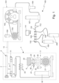
- number 1 denotes as a whole a Nitrox-mixtures production machine, which is capable of delivering a breathing gaseous mixture consisting mainly of oxygen and nitrogen, in which the oxygen percentage is greater than 21% and advantageously also less than 50%.
- the machine 1 is adapted to deliver a substantially binary nitrogen-oxygen gaseous mixture, in which the oxygen percentage is preferably less than 40% and advantageously equal to 32% or 36%.
- the machine 1 in addition, is preferably adapted to be used in or incorporated into a scuba-diving cylinder refilling equipment 100, which is structured so as to fill up one or more scuba-diving cylinders 200 with a breathing gaseous mixture with a pressure preferably higher than 150 bar and advantageously also higher than 200 bar.
- Scuba diving cylinders 200 are pressure vessels substantially cylindrical in shape, known and readily available on the market, so their structure won't be further described.
- the scuba-diving cylinders refilling equipment 100 comprises at least one high-pressure compressor 101, which is specifically structured/ dimensioned for sucking in air or any other gaseous mixture at ambient pressure, and for delivering at outlet a flow of high-pressure air or other gaseous mixture with a supply/delivery pressure preferably greater than 150 bar and advantageously also equal to or greater than 200 bar.
- the Nitrox-mixtures production machine 1 is preferably adapted to be placed upstream of the high-pressure compressor 101, so as to be able to feed, at inlet of the same high-pressure compressor 101, a Nitrox mixture with a predetermined composition.
- the machine 1 is structured so as to be connected to the suction mouth of the high-pressure compressor 101, and is adapted to feed at inlet of the high-pressure compressor 101 a Nitrox gaseous mixture with a predetermined percentage of Oxygen and, consequently, of Nitrogen.
- the high-pressure compressor 101 is preferably a positive displacement reciprocating compressor with a multi-stage structure.
- the high-pressure compressor 101 preferably comprises: a piston pumping assembly 102 with a multistage structure, which has a series of variable-volume pumping chambers connected in cascade one after the other; an electric driving motor 103, which is mechanically coupled to the pumping assembly 102 so as to continuously cyclically vary the volume of the various variable-volume chambers; and preferably also a gas/liquid separator 104, which is located downstream of the piston pumping assembly 102 and is structured so as to retain within itself the droplets of oil and/or condensed water vapour present in the flow of high-pressure air or other gaseous mixture coming out of the pumping assembly 102.
- the delivery of the high-pressure compressor 101 is therefore located downstream of the gas/liquid separator 104.
- the pumping assembly 102 and the drive motor 103 are preferably arranged side by side to one another, advantageously resting on the same supporting platform or frame, so as to form an easily transportable single block.
- the gas/liquid separator 104 is preferably located on the same supporting platform or frame.
- the pumping assembly 102 and the drive motor 103 are moreover connected to each other by means of a drive belt, which is looped around two pulleys fixed one on the shaft of drive motor 103 and the other on the crankshaft of the pumping assembly 102.
- the drive motor 103 may be also an internal combustion engine.
- the high-pressure compressor 101 is moreover provided with a series of heat exchangers (not illustrated), which are located downstream of the various variable-volume chambers of the pumping assembly 102, and are structured so as to cool down the air or other gaseous mixture flowing from a corresponding variable-volume chamber to the next and/or leaving the pumping assembly 102.
- a series of heat exchangers not illustrated
- the drying device 107 is preferably an absorption dryer structured so as to reduce the amount of water vapour in the air leaving the high-pressure compressor 101 to a value less than or equal to 15 mg/m 3 .
- distribution assembly 105 and/or the filtering assembly 106 and/or the dryer device 107 is/are preferably also located/fixed on the supporting platform or frame that supports the pumping assembly 102 and the drive motor 103.
- the high-pressure gas distribution assembly 105 in turn comprises: a distribution manifold 108, which communicates with the delivery of the high-pressure compressor 101 so as to receive the flow of high-pressure air or other gaseous mixture produced by the high-pressure compressor 101, and is provided with one or more manually-operated shut-off valves, separate and independent from each other, each of which is capable of regulating/controlling the exit of the high-pressure air or other gaseous mixture from the same manifold 108; and advantageously also one or more flexible connecting hoses 109, each of which is connected to the distribution manifold 108 so as to communicate with a single, respective shut-off valve of the distribution manifold 108, and is provided with a coupling connector specifically structured to be removably coupled to the valve of any scuba diving cylinder 200.
- a distribution manifold 108 which communicates with the delivery of the high-pressure compressor 101 so as to receive the flow of high-pressure air or other gaseous mixture produced by the high-pressure compressor 101, and is provided with
- the scuba-diving cylinders refilling equipment 100 moreover comprises: a pressure sensor 110, which is located immediately upstream of the distribution assembly 105, or rather upstream of the distribution manifold 108, and is structured to provide as output a (electrical) signal indicative of the pressure value of the high-pressure air or other gaseous mixture arriving in the distribution assembly 105; and an electronic control unit 111, which is connected to the pressure sensor 110 and is programmed/configured to switch off the high-pressure compressor 101, or rather switch off the drive motor 103, when the pressure value of the high-pressure air or other gaseous mixture arriving in the distribution assembly 105 reaches or exceeds a given limit value advantageously comprised between 200 and 300 bar.
- a pressure sensor 110 which is located immediately upstream of the distribution assembly 105, or rather upstream of the distribution manifold 108, and is structured to provide as output a (electrical) signal indicative of the pressure value of the high-pressure air or other gaseous mixture arriving in the distribution assembly 105
- an electronic control unit 111
- the scuba-diving cylinders refilling equipment 100 is finally also equipped with a normally-closed discharge valve 112, which is located immediately upstream of the distribution assembly 105, and more in detail between the dryer device 107 and the distribution assembly 105, and is structured so as to selectively divert/discharge directly outside the flow of high-pressure air or other gaseous mixture arriving from the high-pressure compressor 101, before it may reach the high-pressure gas distribution assembly 105.
- a normally-closed discharge valve 112 which is located immediately upstream of the distribution assembly 105, and more in detail between the dryer device 107 and the distribution assembly 105, and is structured so as to selectively divert/discharge directly outside the flow of high-pressure air or other gaseous mixture arriving from the high-pressure compressor 101, before it may reach the high-pressure gas distribution assembly 105.
- the oxygen percentage of the final Nitrox mixture is lower than or equal to the oxygen percentage of the intermediate Nitrox mixture.
- the outlet of the mixing manifold 4 is moreover structured so as to be connected or connectable directly to the suction mouth of the high-pressure compressor 101, in order to feed said final Nitrox mixture at inlet of the same high-pressure compressor 101.
- Molecular Separator 2 is preferably a semi-permeable membrane molecular separator.
- the Nitrox-mixtures production machine 1 moreover comprises: at least one oxygen sensor 5, which is capable of measuring the percentage of oxygen present in the Nitrox mixture exiting the mixing manifold 4, i.e. the oxygen percentage present in the Nitrox mixture; and an electronic control device 6, which is connected to the oxygen sensor(s) 5, and is adapted to regulate the flowrate of the air flow that the low-pressure compressor 3 feeds at inlet of the molecular separator 2, depending on the signals arriving from the oxygen sensor(s) 5.
- the or at least one of the oxygen sensors 5 is preferably located at the outlet of the mixing manifold 4 or immediately downstream of the mixing manifold 4, and is structured so as to provide as output a signal indicating the percentage of oxygen present in the Nitrox mixture directed towards the suction mouth of the high-pressure compressor 101.
- the electronic control device 6 is adapted to regulate the flowrate of the airflow that the low-pressure compressor 3 feeds at inlet of the molecular separator 2, so as to automatically maintain at a predetermined target value, hereinafter referred to as the target percentage O% 0 , the oxygen percentage of the Nitrox mixture that comes out of the mixing manifold 4 and advantageously enters the suction mouth of the high-pressure compressor 101.
- a predetermined target value hereinafter referred to as the target percentage O% 0
- the oxygen percentage of the Nitrox mixture that comes out of the mixing manifold 4 and advantageously enters the suction mouth of the high-pressure compressor 101.
- Preferably said target percentage 0% 0 is moreover manually selectable by the user among a predetermined range of values.
- the electronic control device 6, in turn, is connected also to the pressure sensor (s) 7, and is adapted to regulate the flowrate of the airflow that the low-pressure compressor 3 feeds at inlet of the molecular separator 2 also based on the signals coming from the pressure sensor or sensor 7.
- the Nitrox-mixtures production machine 1 preferably also includes a preferably electrically-powered, heating device 8, which is interposed between the low-pressure compressor 3 and the molecular separator 2, and is adapted to heat up the airflow that the low-pressure compressor 3 feeds at inlet of the molecular separator 2.
- the electronic control device 6, moreover, is preferably also adapted to command the heating device 8 advantageously so as to bring and maintain the temperature of the airflow entering the molecular separator 2 to a predetermined target value, hereinafter referred to as the target temperature To, which is advantageously comprised between +35°C and +45°C.
- the Nitrox-mixtures production machine 1 is preferably also provided with at least one temperature sensor 9, which is located between the molecular separator 2 and the heating device 8, and is structured so as to provide as outlet a (electrical) signal indicative of the temperature of the air directed towards the molecular separator 2.
- the electronic control device 6, is preferably connected to the temperature sensor(s) 9, and is preferably adapted to command the heating device 8 according to the signals arriving from the temperature sensor(s) 9, so as to bring the temperature of the airflow entering the molecular separator 2 to said target temperature T 0 .
- the electronic control device 6 is preferably also adapted to command the heating device 8 according to the signals arriving from the oxygen sensor(s) 5 and/or according to the signals arriving from the pressure sensor(s) 7.
- the electronic control device 6 is preferably also adapted to vary/modify the value of said target temperature T 0 according to the signals arriving from the oxygen sensor(s) 5 and/or according to the signals arriving from the pressure sensor(s) 7.
- the semi-permeable membrane molecular separator 2 is preferably structured so as to provide at outlet a Nitrox mixture with an oxygen percentage lower than 50% and advantageously ranging between 38% and 45%.
- the molecular separator 2 preferably comprises: a pressure vessel 10 advantageously oblong in shape, which is preferably made of a metal or composite material, and is provided with an inlet and two outlets separate and distinct from each other; an automatic discharge valve 11, which is located at a first outlet of the pressure vessel 10 and is adapted to maintain the pressure of the gas inside the pressure vessel 10 more or less constant at a predetermined value advantageously lower than 20 bar; and a bundle of hollow fibres with a semi-permeable wall (not visible in the figures), which are arranged inside the pressure vessel 10 so as to connect the inlet of the vessel directly with the outlet of the vessel where the discharge valve 11 is located, and are made of a polymeric or composite material having a structure permeable to molecules of oxygen, water vapour, carbon dioxide and, more generally, to molecules with dimensions smaller than those of nitrogen molecules.
- a pressure vessel 10 advantageously oblong in shape, which is preferably made of a metal or composite material, and is provided with an inlet and two outlets separate and distinct from each other
- the pressure sensor(s) 7 is/are preferably mounted on the pressure vessel 10 so as to measure/detect the air pressure within the bundle of hollow fibres of the molecular separator 2.
- the semi-permeable membrane molecular separator 2 and the pressure sensor(s) 7 are components readily available on the market, so they won't be further described.
- the semi-permeable membrane molecular separator 2 operates as follows: while the air flow produced by the low-pressure compressor 3 enters the pressure vessel 10 and flows within the hollow fibres towards the discharge valve 11, most of the molecules of oxygen, carbon dioxide and/or water vapour contained in the air succeed in freely passing through the wall of the hollow fibres, and heads towards the second outlet of the pressure vessel 10. Instead, almost all of the nitrogen molecules contained in the air flowing within the hollow fibres remain confined within the hollow fibres and reach the first outlet of pressure vessel 10, from where they exit the pressure vessel 10 through the discharge valve 11.
- a Nitrox mixture with an oxygen percentage preferably ranging between 38% and 45% comes out of the second outlet of pressure vessel 10.
- the mixing manifold 4 preferably comprises: an oblong and advantageously also substantially rectilinear, tubular body 13, which is provided with an additional mouth spaced apart from the two main mouths located at the two opposite ends of the same tubular body 13; and advantageously also a series of deflecting fins or appendages 14, which are spread within the tubular body 13 and are adapted to create a strong turbulence in the gaseous mixture flowing within the tubular body 13.
- the first end/mouth of the tubular body 13 communicates directly with the outside.
- the second end/mouth of the tubular body 13 is structured so as to be connected directly to the suction mouth of the high-pressure compressor 101, preferably by means of a removable connecting pipe 15.
- the mixing manifold 4 additionally includes a filtering assembly 16, which is located at first end/mouth of tubular body 13, and is adapted to retain the dust suspended in the air entering the tubular body 13.
- a filtering assembly 16 which is located at first end/mouth of tubular body 13, and is adapted to retain the dust suspended in the air entering the tubular body 13.
- the or at least one of the oxygen sensors 5 is preferably fixed on the tubular body 13 at or near the second end/mouth of tubular body 13.
- the or each oxygen sensor 5 moreover consists of an electrochemical oxygen cell of a known type, that provides at output an electrical signal indicative of the value of the oxygen percentage present in the gaseous mixture grazing the cell.
- the heating device 8 preferably comprises: an oblong tubular body 17, which is preferably substantially rectilinear and/or made of metallic material, and is adapted to be crossed by the airflow directed towards the molecular separator 2; and a resistor 18, which is located within the tubular body 17 so as to be lapped and cooled by the airflow passing through the same oblong tubular body 17.
- the or at least one of the temperature sensors 9 is also located/mounted on tubular body 17, at the end/mouth from where the airflow exits the tubular body 17, directed towards the molecular separator 2.
- the low-pressure compressor 3 is preferably structured so as to suck air at ambient pressure and feed the molecular separator 2 with an airflow with a pressure advantageously ranging between 8 and 15 bar.
- the low-pressure compressor 3 is preferably a rotary volumetric compressor.
- the low-pressure compressor 3 is preferably a volumetric screw compressor.
- the low-pressure compressor 3 preferably comprises: a screw pumping assembly 20; an electric drive motor 21, which is mechanically connected to the screw pumping unit 15 so as to drive into rotation the two rotors of the screw pumping assembly 20, advantageously with a predetermined and substantially constant rotation speed; and preferably also a gas/liquid separator 22, which is located downstream of the screw pumping assembly 20, and is structured to retain within itself the droplets of oil and/or condensed water vapour present in the airflow coming out from the pumping assembly 20.
- the low-pressure compressor 3 is preferably also provided with a filtering assembly 23, which is located upstream of the screw pumping assembly 20, and is adapted to retain the dust suspended in the air being sucked in by the low-pressure compressor 3.
- the pumping assembly 20 and the drive motor 21 are moreover arranged side by side to each other, advantageously resting on the same supporting platform or frame, so as to form an easily transportable single block.
- the gas/liquid separator 22 and/or the filtering assembly 23 is/are advantageously located on the supporting platform or frame that hosts the pumping assembly 20 and the drive motor 21.
- the screw pumping assembly 20 and the drive motor 21 are preferably connected to each other by means of a drive belt, which is looped around two pulleys fixed one to the shaft of the drive motor 21 and the other to the shaft of the screw pumping assembly 20.
- the drive motor 21 may drive into rotation the shaft of pumping assembly 20 without the use of belts and/or other intermediate motion transmission parts.
- the molecular separator 2 and/or the mixing manifold 4 and/or the electronic control device 6 and/or the heating device 8 is/are located on the supporting platform or frame that hosts the pumping assembly 20 and the drive motor 21, so as to form an easily transportable single block.
- the electronic control device 6 is adapted to regulate/vay the flowrate of the airflow that is sucked in by the low-pressure compressor 3, or rather by the screw pumping assembly 20, based on both the signals coming from the oxygen sensor(s) 5 and the signals coming from the pressure sensor(s) 7.
- the electronic control device 6 in particular comprises: an electronically-controlled valve assembly 24, which is located upstream of the suction of the low-pressure compressor 3, or rather upstream of the suction mouth of the screw pumping assembly 20, so as to regulate/vary the flowrate of the airflow that is sucked in by the low-pressure compressor 3; and an electronic control unit 25, which is connected to the oxygen sensor(s) 5 and advantageously also to the pressure sensor(s) 7, and is adapted to command the valve assembly 24 based on the signals arriving from both the oxygen sensor (s) 5 and the pressure sensor(s) 7.
- the valve assembly 24 comprises: a control valve 26, which is located upstream of the suction of low-pressure compressor 3, or rather upstream of the suction mouth of the screw pumping assembly 20, and has a movable shutter that regulates, according to its position inside the valve, the flowrate of the airflow that flows towards the suction mouth of the low-pressure compressor 3, advantageously between a maximum and a minimum value; and an electronically-controlled driving device 27, which is adapted to move/shift, on command, the movable shutter of the same control valve 26.
- the electronic control unit 25 is adapted to command the electronically-controlled driving device 27, so as to control, advantageously in real time, the position of the movable shutter of control valve 26.
- the electronic control unit 25 is programmed/configured so as to maintain the oxygen percentage in the Nitrox mixture flowing out of outlet of mixing manifold 4, or rather flowing out of the second end/mouth of tubular body 13, and is advantageously directed towards the suction of high-pressure compressor 101, substantially constant over time and substantially equal to said target percentage O% 0 .
- the electronic control unit 25 is programmed/configured so as to continuously vary/correct the position of the movable shutter of control valve 26 based on signals coming from the oxygen sensor(s) 5, so as to implement a feedback control of the valve assembly 24.
- the electronic control unit 25 is programmed/configured to implement a feedback control of the position of the movable shutter of the control valve 26 based on signals coming from the oxygen sensor(s) 5.
- the electronic control unit 25 is programmed /configured to implement a feedback control of the position of the movable shutter of command valve 26 when the air pressure inside the molecular separator 2 meets certain conditions.
- the driving device 27 preferably comprises: a pneumatic actuator 28, which is adapted to varying the position of the movable shutter of the control valve 26 according to the value of the air pressure that the same actuator receives at its inlet; and an electronically-controlled pressure reducer 29, which is interposed between the pneumatic actuator 28 and the delivery of the low-pressure compressor 3, and is adapted to adjust/vary, on command, the value of the air pressure directed towards the inlet of the pneumatic actuator 28.
- the pneumatic actuator 28 is coupled to, or incorporated into, the control valve 26 so as to freely move/displace the movable shutter of the control valve 26, and the pressure of the air that the pneumatic actuator 28 receives at inlet determines the position assumed by the movable shutter of the valve.
- the pressure of the air that the pressure reducer 29 feeds at inlet of the pneumatic actuator 28 determines the position of the movable shutter of the control valve 26.
- the electronic control unit 25 is preferably adapted to control the pressure reducer 29 so as to feed, at inlet to the pneumatic actuator 28, a flow of pressurised air having a pressure set by the same electronic control unit 25.
- control valve 26 is preferably a butterfly valve or gate valve, and is preferably interposed between the filtering assembly 23 and the suction mouth of the screw pumping assembly 20.
- control valve 26 in addition, is advantageously structured so as to regulate/vary the flowrate of the airflow entering the low-pressure compressor 3 between zero and a predetermined maximum value.
- the pneumatic actuator 28 is preferably a singleacting pneumatic cylinder, which is advantageously incorporated within the control valve 26, and is adapted to move the movable shutter of the control valve 26 preferably by overcoming the force of a counter spring that instead tends to bring and maintain the movable shutter in a closed position.
- the electronic control device 6 is moreover provided with an external control panel 30 or other type of user interface, via which the user can communicate to the electronic control unit 25 the oxygen percentage of the Nitrox mixture that has to come out from the mixing manifold 4 and advantageously reach the suction of the high-pressure compressor 101; and preferably also with a display or other external visualising device 31, which is commanded by the electronic control unit 25 and is capable of displaying the oxygen percentage momentarily set as target percentage O% 0 by the user.
- the visualising device 31 is moreover capable of displaying, advantageously in real time, the value detected by the oxygen sensor(s) 5 and/or the value detected by the pressure sensor(s) 7.
- the electronic control unit 25 and/or the control panel 30 and/or the visualising device 31 are advantageously located within a rigid boxlike enclosure of known type.
- the electronic control unit 25 is moreover connected also to the temperature sensor(s) 9, and is advantageously also adapted to command the heating device 8 based on the signals arriving from the temperature sensor(s) 9 and optionally also based on the signals arriving from the oxygen sensor(s) 5.
- the electronic control unit 25 is preferably programmed/configured so as to independently establishes the target temperature T 0 that the airflow entering the molecular separator 2 must have advantageously choosing it among a predetermined range of values, and then it is adapted to activate and deactivate the heating device 8 so as to heat the airflow directed towards the molecular separator 2 up to this target temperature T 0 .
- the electronic control unit 25 is preferably programmed/configured to command the electric current circulating in the resistor 18 of heating device 8.
- the visualising device 31 is moreover capable of displaying, advantageously in real time, the value measured by said temperature sensor(s) 9.
- the electronic control unit 25 may be programmed/configured to activate and deactivate the heating device 8 in order to heat the airflow headed towards the molecular separator 2 up to a preset and non-adjustable target temperature T 0 , advantageously ranging between +35°C and +45°C.
- the electronic control unit 25 of the electronic control device 6 is finally also adapted to open the discharge valve 112 if the composition of the Nitrox mixture coming out of mixing manifold 4 does not correspond to the set composition.
- the Nitrox-mixtures production machine 1 additionally comprises, upstream of the molecular separator 2 or the heating device 8, a drying device 32 and/or a filtering assembly 33.
- the drying device 32 is adapted to retain at least part of the water vapour present in the airflow coming out of the low-pressure compressor 3, or rather coming out of the screw pumping assembly 20, and is preferably located immediately downstream of the gas/liquid separator 22 or the screw pumping assembly 20.
- the drying device 32 is preferably an absorption dryer structured to reduce the amount of water vapour in the air leaving the low-pressure compressor 3 to a value less than or equal to 15 mg/m 3 .
- the filtering assembly 33 is preferably located between the drying device 32 and the molecular separator 2, or the heating device 8, and is structured so as to retain impurities and other physical and/or biological contaminants present in the airflow directed towards the molecular separator 2.
- the filtering assembly 33 is preferably made up of a series of activated carbon filters arranged in cascade one to the other.
- drying device 32 and/or a filtering assembly 33 is/are located on the supporting platform or frame that hosts the pumping assembly 20 and the drive motor 21, so as to form an easily transportable single block.
- the electronic control unit 25 of electronic control device 6 is programmed/configured so as to carry out a feedback control of the valve assembly 24, or rather of the position of the movable shutter of the control valve 26 of valve assembly 24, based on the signals arriving from the oxygen sensor(s) 5.
- the electronic control unit 25 varies/modifies the position of the movable shutter of control valve 26 suitably commanding the electronically-controlled driving device 27 of valve assembly 24, or rather the pressure regulator 29.
- the electronic control unit 25 is programmed/configured to continuously modify/adjust the position of the movable shutter of control valve 26 based on the signals from the oxygen sensor (s) 5, so as to bring and maintain the oxygen percentage of the Nitrox mixture coming out of mixing manifold 4 to a value substantially equal to the target percentage O% 0 set by the user.
- the electronic control unit 25 By varying the flowrate of the airflow entering the low-pressure compressor 3, in fact, the electronic control unit 25 also varies the flowrate of the airflow entering the molecular separator 2 and, consequently, the flowrate of the flow of intermediate Nitrox mixture entering the mixing manifold 4. Each change in the flowrate of the Nitrox mixture entering into the mixing manifold 4, in turn, results in a change of the oxygen percentage of the Nitrox mixture that comes out of mixing manifold 4 and is sucked in by the high-pressure compressor 101.
- the electronic control unit 25 is moreover programmed/configured so as to carry out the feedback control of the valve assembly 24 when the trend over time of the pressure of the air inside the molecular separator 2 has substantially stabilized over time.
- the electronic control unit 25 is programmed/configured to monitor the air pressure inside the molecular separator 2, and to implement the feedback control of the valve assembly 24, or rather of the pressure reducer 29, when the trend over time of the air pressure inside the molecular separator 2 meets a stable-pressure condition, which is indicative of the fact that the air pressure inside the molecular separator 2 has substantially stabilised over time.
- the electronic control unit 25 is preferably programmed/configured to start the feedback control of the valve assembly 24, when the variations over time of the air-pressure value inside the molecular separator 2 remain within a predetermined tolerance range.
- the electronic control unit 25 is moreover programmed/configured to start the feedback control of the valve assembly 24, when the relative pressure (difference between the absolute pressure and the ambient pressure) of the air inside the molecular separator 2 has exceeded a predetermined minimum threshold.
- this minimum threshold is furthermore greater than or equal to 0,8 bar.
- the electronic control unit 25 is preferably programmed/configured so as to start the feedback control of valve assembly 24, when variations (in absolute value) in the value of the air pressure inside the molecular separator 2 remain below a predetermined maximum threshold advantageously equal to or less than 0,5 bar, for a monitoring time interval greater than 2 s (seconds) and advantageously also lower than 60 s (seconds).
- the stable-pressure condition is met when the variations (in absolute value) of the air-pressure value inside the molecular separator 2 remain below a predetermined maximum threshold advantageously equal to or less than 0,5 bar, for a monitoring time interval of more than 2 s (seconds) and advantageously also less than 60 s (seconds).
- the stable-pressure condition is preferably met when the relative air pressure inside the molecular separator 2 is greater than or equal to 0,8 bar.
- this maximum threshold is preferably equal to 0,3 bar or, more advantageously, equal to 0,2 bar.
- the monitoring time interval is preferably greater than or equal to 5 s (seconds) and/or less than or equal to 30 s (seconds) or, more advantageously, less than or equal to 20 s (seconds).
- the stable-pressure condition is preferably met if variations (in absolute value) of the air-pressure value inside the molecular separator 2 remain below a maximum threshold of approximately 0,1-0,15 bar, at either end of a monitor time interval of approximately 10-15 s (seconds).
- the stable-pressure condition is preferably met when the relative air pressure inside the molecular separator 2 is greater than or equal to 1 bar.
- the electronic control unit 25 is moreover programmed/configured so as to end the feedback control of the valve assembly 24, or rather of the pressure reducer 29, and advantageously also to close the valve assembly 24, upon the occurrence of one or more predetermined operational events.
- the electronic control unit 25 is preferably programmed/configured so as to end the feedback control of the valve assembly 24, and advantageously also to close the valve assembly 24, when a new and different value of the target percentage O% 0 is set via the control panel 30, and/or when a stop signal is received advantageously coming from the control panel 30 (stop of machine 1 decided unilaterally by the user) and/or from the electronic control unit 111 (shutdown of the high-pressure compressor 101).
- the operation of the electronic control device 6 firstly entails:
- the feedback-control step starts after the trend over time of the air pressure in molecular separator 2 has stabilised over time, i.e. after said stable-pressure condition has been met.
- operation of the electronic control device 6 preferably also includes the step of determining an optimal initial position of the movable shutter of control valve 26.
- the optimal initial position is the position that the movable shutter of control valve 26 should likely assume, on the basis of previous operating cycles, such that the machine 1 can deliver a Nitrox mixture having an oxygen percentage substantially equal to the target percentage O% 0 set by the user.
- the step of determining the optimal initial position of the movable shutter of control valve 26 in particular involves estimating, advantageously by means of linear interpolation, said optimal initial position on the basis of a plurality of already known sample positions, which are advantageously associated to Nitrox mixtures with specific oxygen percentages.
- operation of electronic control device 6 preferably includes, at the end of the feedback-control step, a step of verification and possible updating of the sample position or positions based on the parameters used in the feedback-control step that has just ended.
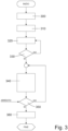
- the electronic control unit 25 preferably starts by determining (block 300) the optimal initial position that the movable shutter of the control valve 26 should assume, so that the machine 1 can likely provided at outlet a Nitrox mixture having an oxygen percentage substantially equal to the target O% 0 set by the user.
- the electronic control unit 25 is preferably programmed/configured to estimate the optimal initial position of the movable shutter of valve assembly 26 by interpolating this initial optimum position from a series of already known sample positions.
- the electronic control unit 25 preferably has a non-volatile memory in which are stored the sample positions that the movable shutter of control valve 26 should assume in order to obtain at least two different values of target percentage 0% 0 , and is preferably programmed/ configured so as to determine the new optimal initial position of the movable shutter of control valve 26 via interpolation based on said sample positions.
- sample positions could be the position of the mobile shutter of control valve 26 associated to a Nitrox gaseous mixture with an oxygen percentage equal to 28% (EAN-28), and the position of the mobile shutter of control valve 26 associated to a Nitrox gaseous mixture with an oxygen percentage equal to 36% (EAN-36).
- EAN-28 Nitrox gaseous mixture with an oxygen percentage equal to 28%
- EAN-36 Nitrox gaseous mixture with an oxygen percentage equal to 36%
- the electronic control unit 25 drives (block 310) the valve assembly 24, or rather the electronically-controlled driving device 27, so as to place the movable shutter of control valve 26 in said optimal initial position.
- the electronic control unit 25 monitors (block 320) the value of the air pressure inside the molecular separator 2, and checks (block 330) whether the trend over time of the air pressure inside the molecular separator 2 has stabilised over time, i.e. whether it meets said set of stable-pressure conditions.
- the electronic control unit 25 starts the feedback control (block 340) of the valve assembly 24 based on signals coming from the oxygen sensor(s) 5.
- the electronic control unit 25 continuously modifies/adjusts the position of the movable shutter of control valve 26 based on the signals coming from the oxygen sensor (s) 5, so as to bring and maintain the oxygen percentage of the Nitrox mixture coming out of mixing manifold 4 at a value substantially equal to the target percentage O% 0 set by the user.
- the electronic control unit 25 preferably ends (block 350) the feedback control of the valve assembly 24 when a predefined stop condition occurs.
- this stop condition includes the setting of a new and different value of the target percentage O% 0 via the control panel 30, and/or the reception by the electronic control unit 25 of a stop signal that advantageously comes from the control panel 30 and/or the electronic control unit 111.
- the electronic control unit 25 After having ended the feedback-control step of valve assembly 24, the electronic control unit 25 finally compares (block 360) the sample position stored internally with the actual position assumed by the movable shutter of control valve 26 during, or at the end of, the feedback operation cycle just completed and, if necessary, takes this actual position as a new sample position.
- the electronic control unit 25 preferably updates the sample position when the difference between the sample position stored internally and the actual position assumed by the movable shutter of control valve 26 during, or at the end of, the last feedback operation cycle exceeds a preset maximum threshold which is advantageously equal to 10-15%.
- the electronic control unit 25 since the position of the movable shutter of control valve 26 is preferably controlled by the pneumatic actuator 28 on the basis of the pressure of the that the pressure reducer 29 feeds at inlet of pneumatic actuator 28, the electronic control unit 25 operates as follows.
- the electronic control unit 25 is preferably programmed/configured to determine (block 300) the value of the optimal initial pressure Pi that should be sent to the pneumatic actuator 28 of valve assembly 24, so that the machine 1 can reasonably provide at outlet of a Nitrox mixture having an oxygen percentage substantially equal to the target percentage O% 0 set by the user.
- the electronic control unit 25 is preferably programmed/configured to estimate the value of said optimal initial pressure Pi on the basis of a plurality of sample pressures, advantageously stored within the same electronic control unit 25.
- the electronic control unit 25 is preferably programmed/configured to calculate/find the value of the optimal initial pressure Pi by interpolation, based on said plurality of already known sample pressures.
- the electronic control unit 25 there are advantageously stored the nominal pressure values (sample pressures), which the air at inlet of pneumatic actuator 28 must have in order to obtain at least two different values of target percentage 0% 0 , and the electronic control unit 25 is preferably programmed/configured to determine said optimal initial pressure Pi by advantageously linear interpolation, based on said nominal pressure values (sample pressures).
- EAN-28 Nitrox gaseous mixture with oxygen percentage
- EAN-36 Nitrox gaseous mixture with oxygen percentage equal to 36%
- the electronic control unit 25 is preferably programmed/configured to drive (block 310) the pressure reducer 29 so that the pneumatic actuator 28 receives at its inlet an airflow having a pressure value equal to said optimal initial pressure Pi.
- the electronic control unit 25 is preferably programmed/ configured to determine (block 320) the momentary pressure of the air inside the molecular separator 2, advantageously based on the signals coming from the pressure sensor(s) 7.
- the electronic control unit 25 is preferably programmed/configured to analyse (block 330) the trend over time of the air pressure in the molecular separator 2, so as to determine whether the trend of the air pressure in the molecular separator 2 has stabilised over time.
- the electronic control unit 25 is preferably programmed/configured to check (block 330) when the trend over time of the air pressure inside the molecular separator 2 meets said stable-pressure condition.
- the electronic control unit 25 is preferably programmed/configured so as to continuously modify/adjust (block 340) the pressure of the air that the pressure reducer 29 feeds at inlet of pneumatic actuator 28 based on the signals coming from the oxygen sensor(s) 5, i.e. carries out the feedback control, so as to bring and maintain the oxygen percentage of the Nitrox mixture coming out of mixing manifold 4 to a value substantially equal to the target percentage O% 0 set by the user.
- the electronic control unit 25 is moreover programmed/configured to reset (block 350) the value of the air pressure that the pressure reducer 29 feed at inlet of pneumatic actuator 28 and to end the feedback control of the pressure reducer 29, when said stop condition occurs.
- the electronic control unit 25 is preferably also programmed/configured so as to update (block 360) the sample pressure stored internally when the difference between the sample pressure stored internally and the air pressure fed to the pneumatic actuator 28 during the last feedback operation cycle is advantageously equal to or greater than 20%.
- the Nitrox-mixtures production machine 1 does not require continuous supervision by the user and, in addition, is also capable of discharging externally the produced Nitrox mixture if its composition does not correspond to that set by the user.
- the particular operating method implemented by the electronic control unit 25, which carries out the feedback control of valve assembly 24 only when the air pressure inside the molecular separator 2 has stabilised makes it possible to minimise the duration of the transients in which the oxygen percentage of the Nitrox mixture coming out of mixing manifold 4 does not correspond to that set by the user, thus reducing the amount of Nitrox mixture that is discharged externally from the scuba-diving cylinders refilling equipment 100.
- the low-pressure compressor 3 may be a lobetype volumetric compressor.
- the automatic discharge valve 11 of molecular separator 2 may be replaced by a simple pressure reducer and/or flow reducer.
- the pneumatic actuator 28 of electronically-controlled valve assembly 24, moreover, could also be supplied with pressurised air coming from a source of pressurised air or other pressurised gas other than the low-pressure compressor 3.
- the pressure reducer 29 would be interposed between the pneumatic actuator 28 and said pressurised-air source.
- the electronically-controlled driving device 27 of valve assembly 24 comprises, in place of the pneumatic actuator 28 and the pressure reducer 29, an electronically-controlled electric or electromechanical actuator 34, which is advantageously provided with a position transducer, and is coupled to the control valve 26 so as to move/displace, on command, the movable shutter of the same valve.
- the electronic control unit 25 directly controls the electric or electromechanical actuator 34.
- the electronic control unit 25 implements the feedback control of the valve assembly 24, or rather the feedback control of the electric or electromechanical actuator 34, when the air pressure inside the molecular separator 2 has stabilised.
Landscapes
- Engineering & Computer Science (AREA)
- Chemical & Material Sciences (AREA)
- Mechanical Engineering (AREA)
- General Engineering & Computer Science (AREA)
- Chemical Kinetics & Catalysis (AREA)
- Analytical Chemistry (AREA)
- Organic Chemistry (AREA)
- General Chemical & Material Sciences (AREA)
- Oil, Petroleum & Natural Gas (AREA)
- Inorganic Chemistry (AREA)
- Oxygen, Ozone, And Oxides In General (AREA)
Applications Claiming Priority (2)
| Application Number | Priority Date | Filing Date | Title |
|---|---|---|---|
| IT102023000005010A IT202300005010A1 (it) | 2023-03-16 | 2023-03-16 | Attrezzatura per la produzione di miscele nitrox |
| IT102023000022266A IT202300022266A1 (it) | 2023-10-24 | 2023-10-24 | Macchina per la produzione di miscele nitrox e relativo metodo di funzionamento |
Publications (2)
| Publication Number | Publication Date |
|---|---|
| EP4464401A1 true EP4464401A1 (de) | 2024-11-20 |
| EP4464401A9 EP4464401A9 (de) | 2025-01-01 |
Family
ID=90363349
Family Applications (2)
| Application Number | Title | Priority Date | Filing Date |
|---|---|---|---|
| EP24163490.6A Pending EP4431175A1 (de) | 2023-03-16 | 2024-03-14 | Nitrox-gemisch-herstellungsmaschine |
| EP24163616.6A Pending EP4464401A1 (de) | 2023-03-16 | 2024-03-14 | Nitrox-mischungen-herstellmaschine und zugehöriges betriebsverfahren |
Family Applications Before (1)
| Application Number | Title | Priority Date | Filing Date |
|---|---|---|---|
| EP24163490.6A Pending EP4431175A1 (de) | 2023-03-16 | 2024-03-14 | Nitrox-gemisch-herstellungsmaschine |
Country Status (2)
| Country | Link |
|---|---|
| US (2) | US20240309996A1 (de) |
| EP (2) | EP4431175A1 (de) |
Citations (5)
| Publication number | Priority date | Publication date | Assignee | Title |
|---|---|---|---|---|
| FR2722425A1 (fr) * | 1994-07-01 | 1996-01-19 | Air Liquide America Corporation | Systeme destine a la compression de l'air et a l'extraction d'azote de l'air comprime |
| EP0851331A1 (de) * | 1996-12-31 | 1998-07-01 | Praxair Technology, Inc. | Vorrichtung und Verfahren zur Membrane-Kontrolle |
| US5846291A (en) * | 1995-08-22 | 1998-12-08 | Undersea Breathing Systems, Inc. | Oxygen enriched air generation system |
| US20050066814A1 (en) * | 2003-09-30 | 2005-03-31 | Nu Venture Diving Company | Apparatus and method for producing nitrox |
| DE102014108874A1 (de) * | 2014-06-25 | 2015-12-31 | Krinner Drucklufttechnik Gmbh | Luftaufbereitungsverfahren und -vorrichtung |
Family Cites Families (16)
| Publication number | Priority date | Publication date | Assignee | Title |
|---|---|---|---|---|
| FR2629555B1 (fr) * | 1988-03-31 | 1990-11-16 | Sogelerg | Vanne numerique |
| US4860803A (en) * | 1988-09-15 | 1989-08-29 | The United States Of America As Represented By The Department Of Commerce | Continuous nitrox mixer |
| US5053058A (en) * | 1989-12-29 | 1991-10-01 | Uop | Control process and apparatus for membrane separation systems |
| FR2695831B1 (fr) * | 1992-09-24 | 1994-11-10 | Air Liquide | Installation et procédé de fourniture d'un mélange gazeux aux voies respiratoires d'un utilisateur. |
| US5992464A (en) * | 1998-01-09 | 1999-11-30 | Cowell; Ross A. | Pre-compression nitrox in-line blender |
| US6395065B1 (en) * | 1999-05-14 | 2002-05-28 | Respironics, Inc. | Air flow control in a gas fractionalization system and associated method |
| US6792846B2 (en) * | 2000-09-26 | 2004-09-21 | Universal Oxygen, Inc. | Gas delivery system |
| US6827084B2 (en) * | 2002-06-21 | 2004-12-07 | Lloyd Thomas Grubb, Jr. | Automatic gas blender |
| US7329304B2 (en) * | 2005-04-05 | 2008-02-12 | Respironics Oxytec, Inc. | Portable oxygen concentrator |
| EA026915B1 (ru) * | 2008-10-14 | 2017-05-31 | Эксонмобил Апстрим Рисерч Компани | Способы и системы для регулирования продуктов горения |
| DE102010003507A1 (de) * | 2010-03-31 | 2011-10-06 | Volker J. Wetzel | Gaspermeationsanlage und Verfahren zur Gaspermeation |
| DK2919888T3 (da) * | 2012-11-14 | 2019-10-14 | Evonik Fibres Gmbh | Styring af gassammensætningen i et gasseparationsanlæg med membraner |
| KR101722045B1 (ko) * | 2016-08-26 | 2017-03-31 | 주식회사 엠에스엘 콤프레서 | 용기 상태 검지형 호흡용 공기 충전기 |
| IT201600098296A1 (it) * | 2016-09-30 | 2018-03-30 | Nardi Compressori Srl | Apparecchiatura perfezionata per l’alimentazione di miscele gassose in ingresso ad un compressore in alta pressione |
| EP3854334A1 (de) * | 2020-01-23 | 2021-07-28 | Erbe Elektromedizin GmbH | Gerät zur speisung eines medizinischen instruments mit einem kältemittel |
| WO2022029888A1 (ja) * | 2020-08-04 | 2022-02-10 | 積水化学工業株式会社 | ガス製造装置、ガス製造システムおよびガス製造方法 |
-
2024
- 2024-03-14 EP EP24163490.6A patent/EP4431175A1/de active Pending
- 2024-03-14 EP EP24163616.6A patent/EP4464401A1/de active Pending
- 2024-03-15 US US18/605,885 patent/US20240309996A1/en active Pending
- 2024-03-15 US US18/605,883 patent/US20240309997A1/en active Pending
Patent Citations (5)
| Publication number | Priority date | Publication date | Assignee | Title |
|---|---|---|---|---|
| FR2722425A1 (fr) * | 1994-07-01 | 1996-01-19 | Air Liquide America Corporation | Systeme destine a la compression de l'air et a l'extraction d'azote de l'air comprime |
| US5846291A (en) * | 1995-08-22 | 1998-12-08 | Undersea Breathing Systems, Inc. | Oxygen enriched air generation system |
| EP0851331A1 (de) * | 1996-12-31 | 1998-07-01 | Praxair Technology, Inc. | Vorrichtung und Verfahren zur Membrane-Kontrolle |
| US20050066814A1 (en) * | 2003-09-30 | 2005-03-31 | Nu Venture Diving Company | Apparatus and method for producing nitrox |
| DE102014108874A1 (de) * | 2014-06-25 | 2015-12-31 | Krinner Drucklufttechnik Gmbh | Luftaufbereitungsverfahren und -vorrichtung |
Also Published As
| Publication number | Publication date |
|---|---|
| US20240309997A1 (en) | 2024-09-19 |
| EP4431175A1 (de) | 2024-09-18 |
| EP4464401A9 (de) | 2025-01-01 |
| US20240309996A1 (en) | 2024-09-19 |
Similar Documents
| Publication | Publication Date | Title |
|---|---|---|
| US6467478B1 (en) | Gas mixing apparatus for a ventilator | |
| US6827084B2 (en) | Automatic gas blender | |
| US5071453A (en) | Oxygen concentrator with pressure booster and oxygen concentration monitoring | |
| US5858064A (en) | Oxygen enriched air generation system | |
| KR100754422B1 (ko) | 제 1 압력 및 제 2 압력으로 가스를 공급하기 위한 장치 및, 변화하는 비율로 제품 가스를 고압 저장기에 충전하는 방법 | |
| US20160178084A1 (en) | Pressure-Setting Regulator | |
| EP2093188A2 (de) | Verfahren zum Erzeugen eines mit Sauerstoff angereicherten Gases für einen Benutzer | |
| EP0423496B1 (de) | Anlage zur Sauerstoffkonzentrierung mit Druckerhöhungseinrichtung und Kontrolle der Sauerstoffkonzentration | |
| EP4464401A9 (de) | Nitrox-mischungen-herstellmaschine und zugehöriges betriebsverfahren | |
| US20100108068A1 (en) | Hybrid electro-pneumatic conserver for oxygen conserving regulator | |
| EP2827971B1 (de) | Verfahren und vorrichtung zur trennung von gasen | |
| US10215171B2 (en) | Apparatus for feeding gas mixtures at the intake of a high pressure compressor | |
| EP2229531B1 (de) | Verdichter und vorrichtung zum komprimieren von zwei gasen auf hohem druck | |
| EP4309765A1 (de) | Verbesserungen an oder im zusammenhang mit gasvorrichtungen | |
| US7387659B2 (en) | Pneumatically operated automatic shutoff circuit for controlling the generation of gas | |
| US12234843B2 (en) | Apparatus for electronically-controlled variable flow inlets and electronically-controlled pneumatic inlet modulation of compressor systems | |
| IT202300022266A1 (it) | Macchina per la produzione di miscele nitrox e relativo metodo di funzionamento | |
| IT202300005010A1 (it) | Attrezzatura per la produzione di miscele nitrox | |
| US11204347B2 (en) | Oxygen sensor test device and method of testing oxygen sensor | |
| US4413951A (en) | Capacity control arrangement for fixed speed compressor | |
| SU472657A1 (ru) | Барокамера |
Legal Events
| Date | Code | Title | Description |
|---|---|---|---|
| PUAI | Public reference made under article 153(3) epc to a published international application that has entered the european phase |
Free format text: ORIGINAL CODE: 0009012 |
|
| STAA | Information on the status of an ep patent application or granted ep patent |
Free format text: STATUS: THE APPLICATION HAS BEEN PUBLISHED |
|
| AK | Designated contracting states |
Kind code of ref document: A1 Designated state(s): AL AT BE BG CH CY CZ DE DK EE ES FI FR GB GR HR HU IE IS IT LI LT LU LV MC ME MK MT NL NO PL PT RO RS SE SI SK SM TR |
|
| STAA | Information on the status of an ep patent application or granted ep patent |
Free format text: STATUS: REQUEST FOR EXAMINATION WAS MADE |
|
| 17P | Request for examination filed |
Effective date: 20250305 |