EP4464800A1 - Cuve de fusion pour four à arc électrique et four à arc électrique - Google Patents
Cuve de fusion pour four à arc électrique et four à arc électrique Download PDFInfo
- Publication number
- EP4464800A1 EP4464800A1 EP23174043.2A EP23174043A EP4464800A1 EP 4464800 A1 EP4464800 A1 EP 4464800A1 EP 23174043 A EP23174043 A EP 23174043A EP 4464800 A1 EP4464800 A1 EP 4464800A1
- Authority
- EP
- European Patent Office
- Prior art keywords
- melting vessel
- cover plate
- recess
- side wall
- electric arc
- Prior art date
- Legal status (The legal status is an assumption and is not a legal conclusion. Google has not performed a legal analysis and makes no representation as to the accuracy of the status listed.)
- Withdrawn
Links
Images

Classifications
-
- F—MECHANICAL ENGINEERING; LIGHTING; HEATING; WEAPONS; BLASTING
- F27—FURNACES; KILNS; OVENS; RETORTS
- F27B—FURNACES, KILNS, OVENS OR RETORTS IN GENERAL; OPEN SINTERING OR LIKE APPARATUS
- F27B3/00—Hearth-type furnaces, e.g. of reverberatory type; Electric arc furnaces ; Tank furnaces
- F27B3/08—Hearth-type furnaces, e.g. of reverberatory type; Electric arc furnaces ; Tank furnaces heated electrically, with or without any other source of heat
- F27B3/085—Arc furnaces
-
- C—CHEMISTRY; METALLURGY
- C21—METALLURGY OF IRON
- C21C—PROCESSING OF PIG-IRON, e.g. REFINING, MANUFACTURE OF WROUGHT-IRON OR STEEL; TREATMENT IN MOLTEN STATE OF FERROUS ALLOYS
- C21C5/00—Manufacture of carbon-steel, e.g. plain mild steel, medium carbon steel or cast steel or stainless steel
- C21C5/52—Manufacture of steel in electric furnaces
- C21C5/5241—Manufacture of steel in electric furnaces in an inductively heated furnace
- C21C5/5247—Manufacture of steel in electric furnaces in an inductively heated furnace processing a moving metal stream while exposed to an electromagnetic field, e.g. in an electromagnetic counter current channel
-
- F—MECHANICAL ENGINEERING; LIGHTING; HEATING; WEAPONS; BLASTING
- F27—FURNACES; KILNS; OVENS; RETORTS
- F27D—DETAILS OR ACCESSORIES OF FURNACES, KILNS, OVENS OR RETORTS, IN SO FAR AS THEY ARE OF KINDS OCCURRING IN MORE THAN ONE KIND OF FURNACE
- F27D1/00—Casings; Linings; Walls; Roofs
- F27D1/0043—Floors, hearths
-
- F—MECHANICAL ENGINEERING; LIGHTING; HEATING; WEAPONS; BLASTING
- F27—FURNACES; KILNS; OVENS; RETORTS
- F27D—DETAILS OR ACCESSORIES OF FURNACES, KILNS, OVENS OR RETORTS, IN SO FAR AS THEY ARE OF KINDS OCCURRING IN MORE THAN ONE KIND OF FURNACE
- F27D11/00—Arrangement of elements for electric heating in or on furnaces
- F27D11/06—Induction heating, i.e. in which the material being heated, or its container or elements embodied therein, form the secondary of a transformer
-
- F—MECHANICAL ENGINEERING; LIGHTING; HEATING; WEAPONS; BLASTING
- F27—FURNACES; KILNS; OVENS; RETORTS
- F27D—DETAILS OR ACCESSORIES OF FURNACES, KILNS, OVENS OR RETORTS, IN SO FAR AS THEY ARE OF KINDS OCCURRING IN MORE THAN ONE KIND OF FURNACE
- F27D11/00—Arrangement of elements for electric heating in or on furnaces
- F27D11/12—Arrangement of elements for electric heating in or on furnaces with electromagnetic fields acting directly on the material being heated
-
- F—MECHANICAL ENGINEERING; LIGHTING; HEATING; WEAPONS; BLASTING
- F27—FURNACES; KILNS; OVENS; RETORTS
- F27D—DETAILS OR ACCESSORIES OF FURNACES, KILNS, OVENS OR RETORTS, IN SO FAR AS THEY ARE OF KINDS OCCURRING IN MORE THAN ONE KIND OF FURNACE
- F27D27/00—Stirring devices for molten material
-
- F—MECHANICAL ENGINEERING; LIGHTING; HEATING; WEAPONS; BLASTING
- F27—FURNACES; KILNS; OVENS; RETORTS
- F27B—FURNACES, KILNS, OVENS OR RETORTS IN GENERAL; OPEN SINTERING OR LIKE APPARATUS
- F27B3/00—Hearth-type furnaces, e.g. of reverberatory type; Electric arc furnaces ; Tank furnaces
- F27B3/10—Details, accessories or equipment, e.g. dust-collectors, specially adapted for hearth-type furnaces
- F27B3/12—Working chambers or casings; Supports therefor
- F27B2003/125—Hearths
-
- F—MECHANICAL ENGINEERING; LIGHTING; HEATING; WEAPONS; BLASTING
- F27—FURNACES; KILNS; OVENS; RETORTS
- F27D—DETAILS OR ACCESSORIES OF FURNACES, KILNS, OVENS OR RETORTS, IN SO FAR AS THEY ARE OF KINDS OCCURRING IN MORE THAN ONE KIND OF FURNACE
- F27D1/00—Casings; Linings; Walls; Roofs
- F27D2001/0059—Construction elements of a furnace
- F27D2001/0066—Movable or removable parts
Definitions
- the invention is in the field of steel production, specifically in the field of steel production with an electric arc furnace.
- the invention relates to a melting vessel, with a closed side wall and a melting vessel bottom with a bottom surface, for an electric arc furnace
- the object of the present invention is, on the one hand, to provide a cost-effective solution and, on the other hand, to enable the different expansion behavior of the materials used.
- the task is solved by the side wall and a first part of the melting vessel bottom, which is connected to the closed side wall, is made of a metal, preferably steel with magnetic properties.
- the recess depends on the size of an electromagnetic stirring device.
- the size of the electromagnetic stirring device depends on the size of the melting vessel and the desired Stirring effect on the melt.
- the recess is closed by a cover plate which has non-magnetic properties, whereby the cover plate has an overlapping support surface which rests on the first partial area.
- the cover plate is mounted in a floating manner and appropriately arranged stops ensure that the cover plate always has an overlapping support surface over the entire circumference of the recess.
- the cover plate normally has a different expansion behavior than the metal from which the rest of the melting vessel base is made. This ensures that the cover plate can expand independently of the rest of the melting vessel base without additional stress being introduced into the melting vessel base due to the expansion behavior of the cover plate.
- the stops ensure that the cover plate does not slip to the point where there is no longer an overlapping support surface.
- the stops can be welded-on plates which prevent further movement in this direction when a side surface of the recess is reached.
- the cover plate is limited by the side wall in such a way that the cover plate always has an overlapping support surface when it slips.
- the size of the recess depends on the size of the electromagnetic stirring device to be used.
- the recess has a projected area of at least 10% of a projected bottom area. In most cases, the melting vessel bottom is not a flat surface, so the projected area is used.
- the size depends on the dimensions of the electromagnetic stirring device and how a magnetic flux generated by the electromagnetic stirring device spreads.
- the recess has at least the size which corresponds to the projected area which has a surface facing the recess of an electromagnetic stirring device which can be arranged underneath.
- the first partial area has a width over the entire circumference of at least 500 mm.
- stops are the side wall of the melting vessel, welded stops on the cover plate, a step in the melting vessel bottom and/or welded stops on the vessel bottom.
- the cover plate is made of one of the following materials: austenitic stainless steel, such as a steel with the material number 1.4828.
- an advantageous embodiment provides that in the region of a tap opening, the cover plate in a maximum displaceable position has no overlap with the tap opening, preferably has at least a distance of 50 mm, particularly preferably has a distance of 100 mm.
- the exact design of the tap hole depends on the shape of the recess. It is also conceivable that the cover plate has a slot or a circular segment-shaped recess.
- a preferred embodiment provides that the cover plate has stiffening plates on an underside which protrude through the recess.
- cover plate is designed in an arched, spherical segment-shaped or curved design. These designs increase static strength, which means that greater loads can be absorbed than with a flat floor.
- the arched design is such that the cover plate has, for example, a circular arc shape.
- the exact arch shape depends on the shape of the melting vessel base.
- the curved design has at least one bending edge and is bent in such a way that the shape is adapted to that of the melting vessel base.
- a further advantageous embodiment provides that the melting vessel has a refractory lining on the cover plate and the first part of the melting vessel bottom and the side wall also has a refractory lining When expanded, the cover plate presses into the brickwork and can thus expand.
- an electric arc furnace comprising a previously described melting vessel and an electromagnetic stirring device arranged on the underside in the second partial region of the melting vessel.
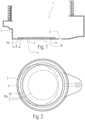
- a melting vessel 1 in the Fig. 1 an embodiment of a melting vessel 1 according to the invention is shown.
- the melting vessel 1 consists of a closed side wall 3 and a melting vessel base 4, the melting vessel base 4 consisting of a first partial area 4b and a second partial area, the second partial area being a recess 5.
- the recess 5 is closed by a cover plate 10.
- This cover plate 10 has non-magnetic properties so that an electromagnetic stirring device placed underneath can work as efficiently as possible and the stirring effect can reach the melt as unhindered as possible.
- the cover plate 5 has stops 11 which prevent the cover plate 5 from slipping so that it always has a support surface on the vessel base 4 around its entire circumference. Furthermore, the stops 11 should also ensure that the cover plate 5 does not overlap with a tap opening 2.
- the stops 11 can also be designed as a stiffening plate so that the cover plate 5 meets the necessary mechanical requirements.
- a width B of the melting vessel bottom 4 is shown, this width B has at least 500mm to provide sufficient support
- a top view of an embodiment of a melting vessel 1 according to the invention is shown.
- the melting vessel 1 also has a recess 5 which is closed with a cover plate 10.
- the melting vessel 1 has a closed side wall 3 which has a lining 6. In a displaced position of the cover plate 10a, the side wall 3 serves as a stop, thus ensuring that the recess 5 always overlaps with the cover plate 10.
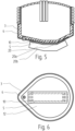
- a melting vessel 1 In the Fig. 3 and Fig. 4 Further embodiments of a melting vessel 1 according to the invention are shown.
- the cover plate 10 has corresponding stops 11, which ensure that when the cover plate 10 slips, there is always an overlap between the recess 5 and the cover plate 10. It is shown in the Fig. 3 and Fig. 5 the overlapping support surface 4a is clearly visible. In the Fig. 4 the stops 11 are attached to the melting vessel bottom 4.
- FIG. 5 and Fig. 6 is a schematic representation of an embodiment of an electric arc furnace with a melting vessel 1 and an electromagnetic stirring device 20.
- the electromagnetic stirring device 20 is arranged directly under the cover plate 20, which covers the recess 5.
- the lining 6 is also shown, which is present both on the melting vessel bottom 4 and on the side wall 3.
- the recess 5 has at least a size that corresponds to the projected area of the facing side 20a of the electromagnetic stirring device 20.
- a projected area of the facing side 20b of the electromagnetic stirring device 20 can, depending on the embodiment, be larger than the projected area of the recess 5.
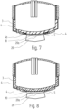
- FIG. 7 and Fig. 8 In each case, an embodiment of an electric arc furnace with a melting vessel base 4, which has a stepped shape in the first partial area 4b, is shown.
- the cover plate 5 is inserted into this stepped shape.
- This stepped shape can also serve as a stop at the same time.
- the cover plate 10 is designed to be curved or spherical segment-shaped.
Landscapes
- Engineering & Computer Science (AREA)
- Mechanical Engineering (AREA)
- General Engineering & Computer Science (AREA)
- Chemical & Material Sciences (AREA)
- Electromagnetism (AREA)
- Physics & Mathematics (AREA)
- Manufacturing & Machinery (AREA)
- Materials Engineering (AREA)
- Metallurgy (AREA)
- Organic Chemistry (AREA)
- Power Engineering (AREA)
- Vertical, Hearth, Or Arc Furnaces (AREA)
- Waste-Gas Treatment And Other Accessory Devices For Furnaces (AREA)
Priority Applications (6)
| Application Number | Priority Date | Filing Date | Title |
|---|---|---|---|
| EP23174043.2A EP4464800A1 (fr) | 2023-05-17 | 2023-05-17 | Cuve de fusion pour four à arc électrique et four à arc électrique |
| CN202480032863.9A CN121127720A (zh) | 2023-05-17 | 2024-05-16 | 用于电弧炉的熔化容器和电弧炉 |
| EP24727338.6A EP4713639A1 (fr) | 2023-05-17 | 2024-05-16 | Récipient de fusion pour four à arc électrique et four à arc électrique |
| KR1020257037935A KR20260012713A (ko) | 2023-05-17 | 2024-05-16 | 전기 아크로용 용융 용기 및 전기 아크로 |
| PCT/EP2024/063623 WO2024236155A1 (fr) | 2023-05-17 | 2024-05-16 | Récipient de fusion pour four à arc électrique et four à arc électrique |
| MX2025013292A MX2025013292A (es) | 2023-05-17 | 2025-11-06 | Recipiente de fusion para un horno de arco electrico y horno de arco electrico |
Applications Claiming Priority (1)
| Application Number | Priority Date | Filing Date | Title |
|---|---|---|---|
| EP23174043.2A EP4464800A1 (fr) | 2023-05-17 | 2023-05-17 | Cuve de fusion pour four à arc électrique et four à arc électrique |
Publications (1)
| Publication Number | Publication Date |
|---|---|
| EP4464800A1 true EP4464800A1 (fr) | 2024-11-20 |
Family
ID=86387232
Family Applications (2)
| Application Number | Title | Priority Date | Filing Date |
|---|---|---|---|
| EP23174043.2A Withdrawn EP4464800A1 (fr) | 2023-05-17 | 2023-05-17 | Cuve de fusion pour four à arc électrique et four à arc électrique |
| EP24727338.6A Pending EP4713639A1 (fr) | 2023-05-17 | 2024-05-16 | Récipient de fusion pour four à arc électrique et four à arc électrique |
Family Applications After (1)
| Application Number | Title | Priority Date | Filing Date |
|---|---|---|---|
| EP24727338.6A Pending EP4713639A1 (fr) | 2023-05-17 | 2024-05-16 | Récipient de fusion pour four à arc électrique et four à arc électrique |
Country Status (5)
| Country | Link |
|---|---|
| EP (2) | EP4464800A1 (fr) |
| KR (1) | KR20260012713A (fr) |
| CN (1) | CN121127720A (fr) |
| MX (1) | MX2025013292A (fr) |
| WO (1) | WO2024236155A1 (fr) |
Citations (3)
| Publication number | Priority date | Publication date | Assignee | Title |
|---|---|---|---|---|
| DE1458942B1 (de) * | 1965-03-23 | 1969-09-25 | Tohoku Special Steel Works Ltd | Anordnung zur Erzeugung einer Badbewegung in Metallschmelzen |
| CA2740528A1 (fr) * | 2008-10-25 | 2010-04-29 | Solios Thermal Ltd. | Appareil pour induire un flux dans une matiere en fusion |
| CN106170353A (zh) * | 2014-06-16 | 2016-11-30 | Abb瑞士股份有限公司 | 用于钢或铝生产工艺的非磁性钢结构 |
-
2023
- 2023-05-17 EP EP23174043.2A patent/EP4464800A1/fr not_active Withdrawn
-
2024
- 2024-05-16 KR KR1020257037935A patent/KR20260012713A/ko active Pending
- 2024-05-16 WO PCT/EP2024/063623 patent/WO2024236155A1/fr not_active Ceased
- 2024-05-16 CN CN202480032863.9A patent/CN121127720A/zh active Pending
- 2024-05-16 EP EP24727338.6A patent/EP4713639A1/fr active Pending
-
2025
- 2025-11-06 MX MX2025013292A patent/MX2025013292A/es unknown
Patent Citations (3)
| Publication number | Priority date | Publication date | Assignee | Title |
|---|---|---|---|---|
| DE1458942B1 (de) * | 1965-03-23 | 1969-09-25 | Tohoku Special Steel Works Ltd | Anordnung zur Erzeugung einer Badbewegung in Metallschmelzen |
| CA2740528A1 (fr) * | 2008-10-25 | 2010-04-29 | Solios Thermal Ltd. | Appareil pour induire un flux dans une matiere en fusion |
| CN106170353A (zh) * | 2014-06-16 | 2016-11-30 | Abb瑞士股份有限公司 | 用于钢或铝生产工艺的非磁性钢结构 |
Also Published As
| Publication number | Publication date |
|---|---|
| KR20260012713A (ko) | 2026-01-27 |
| CN121127720A (zh) | 2025-12-12 |
| WO2024236155A1 (fr) | 2024-11-21 |
| EP4713639A1 (fr) | 2026-03-25 |
| MX2025013292A (es) | 2025-12-01 |
Similar Documents
| Publication | Publication Date | Title |
|---|---|---|
| DD140281A5 (de) | Gekuehlter lichtbogenofenmantel | |
| DE2522650A1 (de) | Waermeisolierungsbauteil fuer einen zylindrischen koerper und verfahren zur waermeisolierung eines zylindrischen koerpers | |
| DE3107454A1 (de) | "anordnung an pfannen oder pfannenoefen fuer gleichstrom" | |
| DE20213759U1 (de) | Kühlplatte für metallurgische Öfen | |
| EP1328364B1 (fr) | Recipient metallurgique et son procede de production | |
| EP4464800A1 (fr) | Cuve de fusion pour four à arc électrique et four à arc électrique | |
| EP0963265B1 (fr) | Cuve pour la metallurgie | |
| DE1782126C3 (de) | Brechringauskleidung fur einen Kreiselbrecher | |
| DE19943287A1 (de) | Kupferkühlplatte für metallurgische Öfen | |
| DE2906711A1 (de) | Industrieofenboden | |
| DE4305974C1 (de) | Metallische Flachdichtung | |
| DE2744311C2 (de) | Induktiv beheizte Gießpfanne | |
| EP0443201A1 (fr) | Four industriel | |
| DE2659827B1 (de) | Lichtbogenschmelzofen | |
| EP0837144A1 (fr) | Panneau de refroidissement pour four à cuve | |
| DE10016096C2 (de) | Ofen zum Glühen von zu Coils gehaspelten Stahlbändern und Verfahren zum Glühen derselben | |
| DE1998816U (de) | Anlagen fuer das widerstandsschweissverfahren | |
| EP1137814A1 (fr) | Plaque de refroidissement et systeme de refroidissement pour paroi de four verticale | |
| EP4522359B1 (fr) | Dispositif de transport de matière fondue | |
| DE2906634A1 (de) | Induktionsofen | |
| DE2843881A1 (de) | Lichtbogenschmelzofen zum schmelzen von metallen, insbesondere von stahl | |
| DE102004056957B4 (de) | Metallurgisches Gefäß zum Transport und zur Behandlung schmelzflüssiger Metalle | |
| AT224149B (de) | Feuerfeste Deckenkonstruktion | |
| AT377602B (de) | Kuehlvorrichtung fuer wandkonstruktionen und/oder deckelkonstruktionen von industrieoefen, insbesondere elektrolichtbogenoefen | |
| DE3405870A1 (de) | Kuehlvorrichtung fuer wandkonstruktionen und/oder deckelkonstruktionen von industrieoefen |
Legal Events
| Date | Code | Title | Description |
|---|---|---|---|
| PUAI | Public reference made under article 153(3) epc to a published international application that has entered the european phase |
Free format text: ORIGINAL CODE: 0009012 |
|
| STAA | Information on the status of an ep patent application or granted ep patent |
Free format text: STATUS: THE APPLICATION HAS BEEN PUBLISHED |
|
| AK | Designated contracting states |
Kind code of ref document: A1 Designated state(s): AL AT BE BG CH CY CZ DE DK EE ES FI FR GB GR HR HU IE IS IT LI LT LU LV MC ME MK MT NL NO PL PT RO RS SE SI SK SM TR |
|
| RAP3 | Party data changed (applicant data changed or rights of an application transferred) |
Owner name: PRIMETALS TECHNOLOGIES AUSTRIA GMBH |
|
| STAA | Information on the status of an ep patent application or granted ep patent |
Free format text: STATUS: THE APPLICATION IS DEEMED TO BE WITHDRAWN |
|
| 18D | Application deemed to be withdrawn |
Effective date: 20250521 |