EP4464841A2 - Procédé d'aspiration de fibres à partir d'une pâte à papier à l'aide d'un dispositif d'aspiration et dispositif d'aspiration - Google Patents
Procédé d'aspiration de fibres à partir d'une pâte à papier à l'aide d'un dispositif d'aspiration et dispositif d'aspiration Download PDFInfo
- Publication number
- EP4464841A2 EP4464841A2 EP24175323.5A EP24175323A EP4464841A2 EP 4464841 A2 EP4464841 A2 EP 4464841A2 EP 24175323 A EP24175323 A EP 24175323A EP 4464841 A2 EP4464841 A2 EP 4464841A2
- Authority
- EP
- European Patent Office
- Prior art keywords
- suction
- cavities
- pulp
- fibers
- tool
- Prior art date
- Legal status (The legal status is an assumption and is not a legal conclusion. Google has not performed a legal analysis and makes no representation as to the accuracy of the status listed.)
- Pending
Links
Images


Classifications
-
- D—TEXTILES; PAPER
- D21—PAPER-MAKING; PRODUCTION OF CELLULOSE
- D21F—PAPER-MAKING MACHINES; METHODS OF PRODUCING PAPER THEREON
- D21F1/00—Wet end of machines for making continuous webs of paper
- D21F1/48—Suction apparatus
-
- D—TEXTILES; PAPER
- D21—PAPER-MAKING; PRODUCTION OF CELLULOSE
- D21J—FIBREBOARD; MANUFACTURE OF ARTICLES FROM CELLULOSIC FIBROUS SUSPENSIONS OR FROM PAPIER-MACHE
- D21J3/00—Manufacture of articles by pressing wet fibre pulp, or papier-mâché, between moulds
- D21J3/10—Manufacture of articles by pressing wet fibre pulp, or papier-mâché, between moulds of hollow bodies
-
- D—TEXTILES; PAPER
- D21—PAPER-MAKING; PRODUCTION OF CELLULOSE
- D21J—FIBREBOARD; MANUFACTURE OF ARTICLES FROM CELLULOSIC FIBROUS SUSPENSIONS OR FROM PAPIER-MACHE
- D21J7/00—Manufacture of hollow articles from fibre suspensions or papier-mâché by deposition of fibres in or on a wire-net mould
Definitions
- a method for sucking fibers from a pulp using a suction device with a suction tool and a suction device for sucking fibers from a pulp with a suction tool are described, which has a plurality of cavities for sucking fibers.
- Fibrous materials are increasingly being used to produce packaging for food (e.g. bowls, capsules, boxes, etc.) and consumer goods (e.g. electronic devices, etc.) as well as beverage containers. Everyday objects such as disposable cutlery and tableware are also made from fibrous materials. Fibrous materials include natural fibers or artificial fibers. Recently, fibrous materials have been increasingly used that contain natural fibers or consist of fibers that can be obtained from renewable raw materials or waste paper, for example. The natural fibers are mixed in a so-called pulp with water and, if necessary, other additives such as starch. Additives can also have an effect on the color, barrier properties and mechanical properties. This pulp can contain natural fibers of, for example, 0.1 to 10% by weight. The proportion of natural fibers varies depending on the process used to produce packaging, etc., and the product properties of the product to be manufactured.
- a fiber processing facility has several stations or forming stations.
- a forming station for example, fibers can be sucked into a cavity of a suction tool, whereby a preform is formed or formed.
- the pulp is made available in a pulp supply and the suction tool with at least one suction cavity, the geometry of which essentially corresponds to the product to be manufactured, is at least partially immersed in the pulp.
- suction takes place via openings in the suction cavity which are connected to a corresponding suction device, with fibers from the pulp collecting on the surface of the suction cavity.
- the sucked-in fibers can then be brought via the suction tool into a pre-pressing tool, where a preform is pre-pressed.
- a preform is pre-pressed.
- elastic molded bodies can be used, for example, which are inflated for pressing and exert pressure on the preforms.
- the fibers in the preform are pressed and the water content of the preform is reduced.
- Preforms are then pressed in a hot press to form finished molded parts.
- preforms are introduced into a hot-pressing tool, which has, for example, a lower tool half and an upper tool half that are heated.
- the preforms are pressed in a cavity with heat input, whereby residual moisture is removed by the pressure and heat, so that the moisture content of the preforms is reduced from approx. 60% by weight before hot-pressing to, for example, 5-10% by weight after hot-pressing.
- a suction tool and a manufacturing process using the methods described above are known, for example, from DE 10 2019 127 562 A1 known.
- a so-called filter cake is preformed from the pulp (cellulose/water mixture) for further processing.
- This preforming usually takes place by suctioning aqueous pulp (primary forms) using negative pressure.
- the aqueous mixture adheres to a filter net, whereby the cellulose fibers in the mold insert (suction cavity) form the filter cake and the excess water in the mixture is transported through a net/membrane that forms the surface of the suction cavity and is thus separated from the pulp.
- the remaining water bound in the filter cake is separated mechanically in further steps by pressing or evaporation.
- the effective volume flow fluctuates greatly due to the statistically greater or less good access/distance to the pulp at a uniform suction negative pressure.
- Mold cavities that are located on edge areas due to the shape of the suction box of a suction tool first clog their mold cavities at a constant negative pressure via a suction unit, whereby the entire volume flow is subsequently available to the inner mold cavities with "closed” outer cavities and then suddenly clogs with more material (fibers) and a higher relative volume flow.
- the task is to provide a solution that provides for the suction of fibers from a pulp, whereby a uniform filter cake formation is achieved for the suction of fibers across several cavities, regardless of the position of the cavities, whereby a uniform weight/material distribution of sucked fibers is achieved for all cavities during a suction process.
- the cycle time for sucking fibers should not be extended compared to classic suction processes.
- the above object is achieved by a method for sucking fibers from a pulp using a suction device with a suction tool having a plurality of cavities, wherein the cavities have a surface with a plurality of openings which are connected via channels to a common suction line, wherein the suction power is changed during a suction process.
- the suction volume flow can be influenced in such a way that the material distribution is even with a comparatively shorter cycle time.
- outer mold cavities can still be the first to become clogged in the suction process in terms of time.
- the volume flow and suction (negative) pressure can be switched, which means that, for example, middle cavities become clogged less or more evenly than the outer cavities.
- switching between at least two states can take place, or the suction tool can be moved in relation to the pulp surface.
- this allows uniform material distribution regardless of the position of the cavities on a suction tool without any loss of cycle time.
- channels also includes spaces through which suction can take place, so that this does not imply any restriction to specific geometries or extensions.
- a negative pressure can be generated in the cavities for suction, whereby the negative pressure for suction has at least two different states. This means that after reaching a definable state with regard to the clogging of the cavity surface or after a period of time, a switch can take place so that the suction effect on the already clogged cavities decreases due to the different pressure states and thus only little/no further material accumulates there, whereas the relatively free cavities have a sufficient suction effect.
- the suction power can be changed continuously or in stages. This makes it possible to achieve a very precise distribution, as the clogging is adjusted either continuously or in stages.
- the change in the suction power can be changed automatically or manually.
- An automatic change can, for example, be specified according to previously determined suction times and pressures or based on measured information.
- a manual change can be adjusted and/or changed, for example, by entering process or product information.
- the change in suction power can be controlled or regulated according to the geometry of the cavities, the position of the cavities on the suction tool, the duration of suction, the pulp composition, properties and/or temperature, the weight of fibers already sucked in, the clogging of the cavities, etc.
- the arrangement of the cavities can be taken into account - for example, cavities can be arranged in a circle around a central cavity, which results in a gradual change in suction power from the outside to the inside.
- the suction power can be changed for each group/frame according to the distance to the center or the edge.
- At least one of the above-mentioned states or properties can be monitored and, once limit values have been reached, a change in the intake power can be initiated via the control device.
- Sensor units can be provided for this purpose, which, for example, determine a change in the volume flow during an intake process when clogging and initiate a change depending on the value.
- a suction device for sucking fibers from a pulp with a suction tool which has a plurality of cavities for sucking fibers, wherein the cavities have a surface with a plurality of openings which are connected via channels to a common suction line, comprising a control device via which the suction power can be changed during a suction process.
- a uniform weight/material distribution can be achieved in the individual cavities in a wet fiber process. This ensures that a uniform product quality of molded parts made of a fiber-containing material is achieved in a subsequent hot pressing process.
- the drying time is determined according to the cavity with the greatest material weight (filter cake; preform). so that there are no differences in the results of hot-pressed/dried molded parts with the same material weight.
- control device can have at least one valve that is designed to change the cross-section of the common intake line to change the intake power.
- switching between pressure levels can be carried out both by throttling (pressure elimination) in a bypass, and with several basic pressures or leakage air via a bypass.
- a bypass valve can be arranged in the common intake line, which can throttle the effective volume flow during intake via the adjustable cross-section.
- the suction device can have at least one sensor unit for monitoring at least the suction pressure in the channels and/or the suction line, the suction duration, the pulp composition, properties and/or temperature, the weight of fibers already sucked in, the clogging of the cavities, wherein the at least one sensor unit is connected to the control device, which is designed to carry out a change in the suction power in accordance with the feedback provided by the at least one sensor unit.
- the switching or change in the suction power can thus take place depending on the actual suction state, so that the product quality of the molded parts to be produced is further improved.
- Fig. 1 shows a schematic representation of a fiber processing device 1000 for producing three-dimensional molded parts from a fiber-containing material.
- the fiber-containing material for producing molded parts is prepared in a pulp tank 200 of the fiber processing device 1000.
- water and fiber materials, as well as additives if necessary can be introduced into a pulp tank 200 via a liquid supply and the pulp can be prepared in the pulp tank 200 by mixing the individual components with heat input and aids, such as a stirrer.
- Pulp is an aqueous solution that contains fibers, whereby the fiber content of the aqueous solution can be in a range of 0.1 to 10% by weight.
- additives such as starch, chemical additives, wax, etc. can be included.
- the fibers can be, for example, natural fibers such as cellulose fibers or fibers from a fiber-containing source material (e.g. waste paper).
- a fiber processing plant offers the possibility of processing pulp in large quantities and making it available to several fiber processing facilities 1000.
- the fiber processing device 1000 can be used to produce, for example, biodegradable cups 3000, capsules, bowls, plates and other shaped and/or packaging parts (e.g. as holder/support structures for electronic devices). Since a fibrous pulp with natural fibers is used as the starting material for the products, the products produced in this way can themselves be used as starting material for the production of such products after their use or can be composted because they can generally be completely decomposed and do not contain any harmful, environmentally hazardous substances.
- the fiber processing device 1000 shown has a frame 100 that can be surrounded by a casing.
- the supply units 300 of the fiber processing device 1000 comprise, for example, interfaces for the supply of media (e.g. water, pulp, compressed air, gas, etc.) and energy (power supply), a central control unit 310, at least one suction device 320, line systems for the various media, pumps, valves, lines, sensors, measuring devices, a BUS system, etc. as well as interfaces for bidirectional communication via a wired and/or wireless data connection.
- media e.g. water, pulp, compressed air, gas, etc.
- energy (power supply) energy (power supply)
- a central control unit 310 at least one suction device 320
- line systems for the various media, pumps, valves, lines, sensors, measuring devices, a BUS system, etc. as well as interfaces for bidirectional communication via a wired and/or wireless data connection.
- a data connection via a fiber optic cable can also exist.
- the data connection can exist, for example, between the control unit 310 and a central control for several fiber processing devices 1000, to a fiber processing plant, to a service point and/or other facilities.
- the fiber processing device 1000 can also be controlled via a bidirectional data connection using a mobile device, such as a smartphone, tablet computer or the like.
- the control unit 310 is in bidirectional communication with an HMI panel 700 via a BUS system or a data connection.
- the HMI (Human-Machine Interface) panel 700 has a display which shows operating data and states of the fiber processing device 1000 for selectable components or the entire fiber processing device 1000.
- the display can be designed as a touch display so that settings can be made manually by an operator of the Fiber processing device 1000 can be made. Additionally or alternatively, further input means such as a keyboard, a joystick, a keypad, etc. can be provided on the HMI panel 700 for operator inputs. Settings can be changed and the operation of the fiber processing device 1000 can be influenced using these.
- the fiber processing device 1000 has a robot 500.
- the robot 500 is designed as a so-called 6-axis robot and is thus able to pick up parts, rotate them and move them in all spatial directions within its radius of action.
- other handling devices can also be provided which are designed to pick up and twist products or to rotate them and move them in the various spatial directions.
- such a handling device can also be designed differently, whereby the arrangement of the corresponding stations of the fiber processing device 1000 can deviate from the embodiment shown.
- a suction tool 520 is arranged on the robot 500.
- the suction tool 520 has cavities designed as a negative of the three-dimensional molded parts to be formed, such as cups 3000, as suction cavities.
- the cavities can, for example, have a net-like surface to which fibers from the pulp attach during suction. Behind the net-like surfaces, the cavities are connected to a suction device via channels in the suction tool 520.
- the suction device can be implemented, for example, by a suction device 320. Pulp can be sucked in via the suction device if the suction tool 520 is located within the pulp basin 200 in such a way that the cavities 522 are at least partially located in the aqueous fiber solution, the pulp.
- a vacuum or a negative pressure for sucking in fibers when the suction tool 520 is in the pulp tank 200 and the pulp can be provided via the suction device 320.
- the fiber processing device 1000 has corresponding means in the supply units 300.
- the suction tool 520 has lines for providing the vacuum/negative pressure from the suction device 320 in the supply units 300 to the suction tool 520 and the openings in the cavities 522. Valves are arranged in the lines, which can be controlled via the control unit 310 and thus regulate the suction of the fibers.
- the suction device 320 can also "blow out", for which purpose the suction device 320 is switched to a different operating mode depending on its design.
- the suction tool 520 When producing molded parts from a fiber material, the suction tool 520 is immersed in the pulp and a negative pressure/vacuum is applied to the openings of the cavities 522 so that fibers are sucked out of the pulp and, for example, attach themselves to the network of cavities 522 of the suction tool 520.
- the robot 500 then lifts the suction tool 520 out of the pulp tank 200 and moves it with the fibers adhering to the cavities 522, which still have a relatively high moisture content of, for example, more than 80% by weight of water, to the pre-pressing station 400 of the fiber processing device 1000, wherein the negative pressure in the cavities 522 is maintained for the transfer.
- the pre-pressing station 400 has a pre-pressing tool with pre-pressing molds.
- the pre-pressing molds can, for example, be designed as a positive of the molded parts to be produced and have an appropriate size with regard to the shape of the molded parts in order to accommodate the fibers adhering in the cavities 522.
- the suction tool 520 with the fibers adhering to the cavities is moved to the pre-pressing station 400 so that the fibers are pressed into the cavities 522.
- the fibers in the cavities are pressed together, creating a stronger bond between the fibers.
- the moisture content of the preforms formed from the sucked-in fibers is reduced, so that the preforms formed after pre-pressing only have a moisture content of, for example, 60% by weight.
- Flexible pre-pressing molds can be used to press out water, which are inflated using compressed air (process air), for example, and press the fibers against the wall of a cavity of another suction tool part. By “blowing up,” water is both squeezed out and the thickness of the sucked-in fiber layer is reduced.
- liquid or pulp can be sucked out and returned via the suction tool 520 and/or via further openings in pre-pressing molds or tool parts (cavities).
- the liquid or pulp generated during suction via the suction tool 520 and/or during Pre-pressing liquid or pulp emerging from the pre-pressing station 400 can be returned to the pulp basin 200.
- the preforms produced in this way are moved on the suction tool 520 via the robot 500 to a hot-pressing station 600.
- the negative pressure is maintained on the suction tool 520 so that the preforms remain in the cavities 522.
- the preforms are transferred via the suction tool 520 to a lower tool body, which can be moved along the production line from the hot-pressing device 610. If the lower tool body is in its extended position, the suction tool 520 is moved to the lower tool body so that the preforms can be placed on the molding devices of the lower tool body.
- An overpressure is then generated via the openings in the suction tool 520 so that the preforms are actively deposited from the cavities 522, or the suction is stopped so that the preforms remain on the molding devices of the lower tool body due to gravity.
- the suction tool 520 is moved away from the robot 500 and the suction tool 520 is immersed into the pulp tank 200 to suck in further fibers for producing molded parts from fibrous material.
- the lower tool body moves after the transfer of the preforms to the hot pressing station 600.
- the preforms are pressed into finished molded parts under heat input and high pressure, for which purpose an upper tool body is brought onto the lower tool body via a press.
- the upper tool body has cavities corresponding to the molding devices.
- the lower tool body and the upper tool body are moved away from each other relatively and the upper tool body is moved along the fiber processing device 1000 in the direction of production, whereby after the hot pressing the finished molded parts are sucked in via the upper tool body and thus remain within the cavities.
- the finished molded parts are thus removed from the hot pressing station 600 and deposited via the upper tool body after the process on a conveyor belt of a conveyor device 800.
- the suction via the upper tool body is stopped and the molded parts remain on the conveyor belt.
- the upper tool body returns to the hot-pressing station 600 and another hot-pressing process can be carried out.
- the fiber processing device 1000 also has a conveyor device 800 with a conveyor belt.
- the molded parts made of fiber-containing material can be placed on the conveyor belt after the final molding and hot pressing in the hot pressing station 600 and removed from the fiber processing device 1000.
- further processing can take place, such as filling and/or stacking the products. Stacking can be done, for example, using an additional robot or another device.
- the fiber processing device 1000 from Fig. 1 shows a possible embodiment.
- a fiber processing device according to the technical teaching described herein can also have only one forming station with an exchangeable tool, for example a suction tool 520 or a hot-pressing tool in which fiber-containing material can be processed, wherein different tools for producing different three-dimensional molded parts can be accommodated in the at least one forming station.
- the other for the fiber processing device 1000 of Fig. 1 The stations and devices shown are not absolutely necessary for the implementation of the technical teaching.
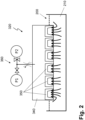
- Fig. 2 shows a schematic representation of a suction process with a suction device 320.
- the suction device 320 has a suction tool 340 with a plurality of cavities 350.
- the arrangement of the cavities 350 on the underside of the suction tool 340 can, as in Fig. 3 shown schematically for different tool designs.
- cavities 350 can be round, oval or polygonal instead of having a rectangular cross-section when viewed towards the underside of the suction tool 340.
- cavities of suction tools 340 can be arranged in a circular or polygonal manner.
- the cavities 350 have a net-like structure on the inner intake surface. Channels extend from the net-like structure within the suction tool 340, which converge in a common suction line for all channels of the cavities 350. A negative pressure for sucking in fibers is applied via the common suction line when the suction tool 340 is located in the pulp 210 in such a way that the fibers can be sucked in via the inner surface of the cavities 350.
- the suction line is connected to a control device 360, which in the embodiment shown has a throttle valve.
- the cross-section of the suction line can be changed via the throttle valve, so that in the schematically shown example two different pressure states P1 and P2 can be set for sucking in fibers from the pulp 210.
- the intake negative pressure P2 can, for example, be between 0.7 and 0.9 bar absolute pressure. In other versions, the pressure can be changed gradually or continuously, for example by changing the free cross-section in the intake line.
- the intake negative pressure can be determined according to the information from at least one sensor unit, which, for example, records the volume or mass flow in the intake line and passes it on to the control device 360. As soon as the volume or mass flow exceeds at least one limit value, the intake pressure can be switched to at least one other pressure level or the intake negative pressure can be changed continuously.
- a change in the suction pressure can additionally or alternatively be achieved by moving the suction tool 320 relative to the pulp surface in the pulp tank 200. It is essential that the cavities 350 lie in one plane and that the suction tool 320 with the cavities 350 is moved parallel to the surface so that the resulting change in pressure has the same effect for all cavities 350. This also applies to suction in the pulp tank 200 in general, whereby a suction pressure only can act evenly if the pressure situation in the cavities 350 is the same (ie, for example, no inclined immersion of the suction tool 320, etc.).
- the pressure change by a displacement of the suction tool 320 during the suction process can, for example, take place continuously or in stages, whereby at least two stages can be provided.
- the pulp 210 can be present, for example, as an aqueous fiber mixture in concentrations of 0.2%-1.5% by weight of fibers in a pulp tank 200, from which the suction tool 320 sucks in the required amount of pulp 210 or fibers, as in Fig. 2 shown schematically via the arrows.
- the resulting intake volume flow depends essentially on the shape and arrangement of the cavities 350 of the intake tool 320.
- the outer cavities 350 become clogged first. This is due, on the one hand, to the fact that more fiber material can be fed into the outer area over the entire lower surface of the suction tool 320.
- the amount of fiber material sucked in is lower in the inner cavities 350 because there are other cavities 350 in the immediate vicinity that also suck in fiber material.
- the inner cavities 350 would suddenly suck in more fiber material if the initial suction negative pressure is maintained, so that they would ultimately contain the most material. Therefore, after a period of time that can be determined in advance or, as stated above, by measuring parameters, at least a switch is carried out so that the suction negative pressure is reduced. This ensures that the inner cavities 350 do not become clogged excessively. As a result, all cavities 350 are evenly clogged.
- Fig. 3 the undersides of suction tools 320 with multiple cavities 350 are shown.
- the suction tool 320 has two inner cavities 350 and ten outer cavities 350.
- the dashed line surrounds the inner cavities 350 and illustrates the two different cavity groups.
- two different suction pressures cf. P1 and P2 are sufficient here.
- a suction tool 320 which has three groups I., II., III. of cavities 350.
- a step-by-step switchover can be carried out for each of the groups I., II., III.
- the switchover can be carried out time-dependently or after exceeding or falling below limit values, which are compared with parameters which are recorded by at least one sensor unit and transmitted to the control device 360.
- the control direction 360 can, as a result of the transmitted information or by a specification, change, for example, the opening cross-section of a common suction line via a valve or another device.
- the cavities 350 of the first group are first filled.
- the initial suction negative pressure is changed after a first time interval.
- the clogging of the second group of cavities 350 then increases, so that after a second time interval the changed suction negative pressure is changed again, whereby the cavities 350 of the third group in the middle of the suction tool 320 finally become filled and the sucked-in fiber material in the cavities 350 has the final weight or amount of fibers.
Landscapes
- Engineering & Computer Science (AREA)
- Manufacturing & Machinery (AREA)
- Paper (AREA)
- Preliminary Treatment Of Fibers (AREA)
Applications Claiming Priority (1)
| Application Number | Priority Date | Filing Date | Title |
|---|---|---|---|
| DE102023112891.4A DE102023112891A1 (de) | 2023-05-16 | 2023-05-16 | Verfahren zum Ansaugen von Fasern aus einer Pulpe unter Verwendung einer Ansaugeinrichtung und Ansaugeinrichtung |
Publications (2)
| Publication Number | Publication Date |
|---|---|
| EP4464841A2 true EP4464841A2 (fr) | 2024-11-20 |
| EP4464841A3 EP4464841A3 (fr) | 2025-08-06 |
Family
ID=91076519
Family Applications (1)
| Application Number | Title | Priority Date | Filing Date |
|---|---|---|---|
| EP24175323.5A Pending EP4464841A3 (fr) | 2023-05-16 | 2024-05-13 | Procédé d'aspiration de fibres à partir d'une pâte à papier à l'aide d'un dispositif d'aspiration et dispositif d'aspiration |
Country Status (3)
| Country | Link |
|---|---|
| US (1) | US20240384468A1 (fr) |
| EP (1) | EP4464841A3 (fr) |
| DE (1) | DE102023112891A1 (fr) |
Families Citing this family (1)
| Publication number | Priority date | Publication date | Assignee | Title |
|---|---|---|---|---|
| US20240367079A1 (en) * | 2023-05-02 | 2024-11-07 | Koslow Technologies Corporation | Water Filter and Medium Therefor |
Citations (1)
| Publication number | Priority date | Publication date | Assignee | Title |
|---|---|---|---|---|
| DE102019127562A1 (de) | 2019-10-14 | 2021-04-15 | Kiefel Gmbh | Faserformanlage zur herstellung von formteilen aus umweltverträglich abbaubarem fasermaterial |
Family Cites Families (6)
| Publication number | Priority date | Publication date | Assignee | Title |
|---|---|---|---|---|
| US2925863A (en) * | 1953-10-12 | 1960-02-23 | Diamond National Corp | Pulp molding machine |
| US3449207A (en) * | 1965-09-03 | 1969-06-10 | Beloit Corp | Dual orifice vacuum forming mold |
| US5656135A (en) * | 1993-02-16 | 1997-08-12 | Moulded Fibre Technology, Inc. | Molded product manufacturing apparatus and methods |
| US6716319B2 (en) * | 2001-09-18 | 2004-04-06 | Regale Corporation | Molded pulp product and apparatus and method for producing the same |
| CN114096713B (zh) * | 2019-05-06 | 2024-08-27 | 祖美股份有限公司 | 用于生产模制纤维产品的系统和方法 |
| GB2616479B (en) * | 2022-03-11 | 2024-10-16 | Pulpex Ltd | Method of and system for forming a receptacle |
-
2023
- 2023-05-16 DE DE102023112891.4A patent/DE102023112891A1/de active Pending
-
2024
- 2024-05-13 EP EP24175323.5A patent/EP4464841A3/fr active Pending
- 2024-05-16 US US18/666,138 patent/US20240384468A1/en active Pending
Patent Citations (1)
| Publication number | Priority date | Publication date | Assignee | Title |
|---|---|---|---|---|
| DE102019127562A1 (de) | 2019-10-14 | 2021-04-15 | Kiefel Gmbh | Faserformanlage zur herstellung von formteilen aus umweltverträglich abbaubarem fasermaterial |
Also Published As
| Publication number | Publication date |
|---|---|
| US20240384468A1 (en) | 2024-11-21 |
| DE102023112891A1 (de) | 2024-11-21 |
| EP4464841A3 (fr) | 2025-08-06 |
Similar Documents
| Publication | Publication Date | Title |
|---|---|---|
| EP4045713B1 (fr) | Installation de mise en forme de fibres destinée à la fabrication d'articles moulés en matière fibreuse biodégradable | |
| DE202023105782U1 (de) | Formkörper für ein Vorpresswerkzeug und Vorpresswerkzeug | |
| DE102022111908A1 (de) | Formeinrichtung zum formen von erzeugnissen aus faserhaltigem material, faserformanlage, verfahren zum formen von erzeugnissen aus faserhaltigem material und erzeugnis aus faserhaltigem material | |
| DE102022108122A1 (de) | Verfahren zur regelung einer heisspresseinrichtung, werkzeugkomponente für eine heisspresseinrichtung und heisspresseinrichtung | |
| EP4045712B1 (fr) | Production de pièces moulées en matériau fibreux, ledit matériau fibreux étant dégradable d'une manière respectueuse de l'environnement | |
| EP4464841A2 (fr) | Procédé d'aspiration de fibres à partir d'une pâte à papier à l'aide d'un dispositif d'aspiration et dispositif d'aspiration | |
| EP4434720B1 (fr) | Moule pour la fabrication de pièces moulées et procédé de fabrication de pièces moulées à l'aide d'un moule | |
| EP4477403A1 (fr) | Procédé de prétraitement de matériau fibreux, chambre de prétraitement et installation de moulage de fibres | |
| EP4675042A1 (fr) | Corps moulé pour un outil de presse de pressage pour le pressage de préformes tridimensionnelles à partir d'un matériau fibreux et poste de presse | |
| EP3804959A1 (fr) | Dispositif d'emboutissage profond des corps d'emballage, par exemple des barquettes d'emballage, en feuille à emboutir | |
| EP4345209A1 (fr) | Moule et procédé de régulation de la répartition de température dans un moule pour produits tridimensionnels | |
| EP4321684A1 (fr) | Dispositif de traitement de fibres comprenant une unité d'alignement pour déplacer et positionner des fibres et procédé de fonctionnement d'un dispositif de traitement de fibres | |
| EP4480692A1 (fr) | Procédé de traitement de bandes de matériau plates à partir d'un matériau contenant des fibres | |
| DE19655149C2 (de) | Verfahren zur Herstellung trockengepreßter Formlinge | |
| DE102022125886A1 (de) | Verfahren zur herstellung von dreidimensionalen formteilen aus einem faserhaltigen material und faserverarbeitungseinrichtung | |
| DE202023105781U1 (de) | Formkörper für ein Vorpresswerkzeug und Vorpresswerkzeug | |
| DE202023105783U1 (de) | Formkörper für ein Vorpresswerkzeug und Vorpresswerkzeug | |
| DE4391896C2 (de) | Form, insbesondere zum Formen von Keramikprodukten | |
| EP4464840A2 (fr) | Procédé de régulation de température dans un moule pour la fabrication de pièces moulées en matériau fibreux et poste de moulage doté d'un moule | |
| EP4553223A1 (fr) | Procédé de moulage de produits en matière fibreuse et dispositif de moulage | |
| EP4530397A1 (fr) | Dispositif d'alimentation en courant gazeux d'un outil de formage de pieces moulees, outil equipe d'un tel dispositif et procede de commande de l'alimentation en courant gazeux | |
| DE102024107894A1 (de) | Werkzeug für eine Verarbeitung von faserhaltigem Material, Formanlage und Verfahren zur Herstellung von faserhaltigen Erzeugnissen | |
| DE2901133C2 (de) | Hydraulische Presse | |
| DE102023112887A1 (de) | Verfahren zum Betreiben mindestens einer Einrichtung für die Verarbeitung von faserhaltigem Material zur Herstellung von dreidimensionalen Formteilen und Einrichtung dazu | |
| EP4538029A1 (fr) | Procédé de pressage d'essai de pièces moulées dans une presse rotative ainsi que presse rotative |
Legal Events
| Date | Code | Title | Description |
|---|---|---|---|
| PUAI | Public reference made under article 153(3) epc to a published international application that has entered the european phase |
Free format text: ORIGINAL CODE: 0009012 |
|
| STAA | Information on the status of an ep patent application or granted ep patent |
Free format text: STATUS: THE APPLICATION HAS BEEN PUBLISHED |
|
| AK | Designated contracting states |
Kind code of ref document: A2 Designated state(s): AL AT BE BG CH CY CZ DE DK EE ES FI FR GB GR HR HU IE IS IT LI LT LU LV MC ME MK MT NL NO PL PT RO RS SE SI SK SM TR |
|
| PUAL | Search report despatched |
Free format text: ORIGINAL CODE: 0009013 |
|
| AK | Designated contracting states |
Kind code of ref document: A3 Designated state(s): AL AT BE BG CH CY CZ DE DK EE ES FI FR GB GR HR HU IE IS IT LI LT LU LV MC ME MK MT NL NO PL PT RO RS SE SI SK SM TR |
|
| RIC1 | Information provided on ipc code assigned before grant |
Ipc: D21J 3/10 20060101AFI20250703BHEP Ipc: D21J 7/00 20060101ALI20250703BHEP |
|
| STAA | Information on the status of an ep patent application or granted ep patent |
Free format text: STATUS: REQUEST FOR EXAMINATION WAS MADE |
|
| 17P | Request for examination filed |
Effective date: 20251029 |