EP4464862A1 - Charnière pour porte ou fenêtre - Google Patents
Charnière pour porte ou fenêtre Download PDFInfo
- Publication number
- EP4464862A1 EP4464862A1 EP24174755.9A EP24174755A EP4464862A1 EP 4464862 A1 EP4464862 A1 EP 4464862A1 EP 24174755 A EP24174755 A EP 24174755A EP 4464862 A1 EP4464862 A1 EP 4464862A1
- Authority
- EP
- European Patent Office
- Prior art keywords
- plate
- channel
- hinge
- fixing
- hinge body
- Prior art date
- Legal status (The legal status is an assumption and is not a legal conclusion. Google has not performed a legal analysis and makes no representation as to the accuracy of the status listed.)
- Pending
Links
Images

Classifications
-
- E—FIXED CONSTRUCTIONS
- E05—LOCKS; KEYS; WINDOW OR DOOR FITTINGS; SAFES
- E05D—HINGES OR SUSPENSION DEVICES FOR DOORS, WINDOWS OR WINGS
- E05D3/00—Hinges with pins
- E05D3/02—Hinges with pins with one pin
-
- E—FIXED CONSTRUCTIONS
- E05—LOCKS; KEYS; WINDOW OR DOOR FITTINGS; SAFES
- E05D—HINGES OR SUSPENSION DEVICES FOR DOORS, WINDOWS OR WINGS
- E05D5/00—Construction of single parts, e.g. the parts for attachment
- E05D5/02—Parts for attachment, e.g. flaps
- E05D5/0215—Parts for attachment, e.g. flaps for attachment to profile members or the like
- E05D5/0223—Parts for attachment, e.g. flaps for attachment to profile members or the like with parts, e.g. screws, extending through the profile wall or engaging profile grooves
- E05D5/0238—Parts for attachment, e.g. flaps for attachment to profile members or the like with parts, e.g. screws, extending through the profile wall or engaging profile grooves with parts engaging profile grooves
-
- E—FIXED CONSTRUCTIONS
- E05—LOCKS; KEYS; WINDOW OR DOOR FITTINGS; SAFES
- E05D—HINGES OR SUSPENSION DEVICES FOR DOORS, WINDOWS OR WINGS
- E05D7/00—Hinges or pivots of special construction
- E05D7/04—Hinges adjustable relative to the wing or the frame
- E05D7/0415—Hinges adjustable relative to the wing or the frame with adjusting drive means
-
- E—FIXED CONSTRUCTIONS
- E05—LOCKS; KEYS; WINDOW OR DOOR FITTINGS; SAFES
- E05D—HINGES OR SUSPENSION DEVICES FOR DOORS, WINDOWS OR WINGS
- E05D7/00—Hinges or pivots of special construction
- E05D7/04—Hinges adjustable relative to the wing or the frame
- E05D7/0415—Hinges adjustable relative to the wing or the frame with adjusting drive means
- E05D7/0423—Screw-and-nut mechanisms
-
- E—FIXED CONSTRUCTIONS
- E05—LOCKS; KEYS; WINDOW OR DOOR FITTINGS; SAFES
- E05D—HINGES OR SUSPENSION DEVICES FOR DOORS, WINDOWS OR WINGS
- E05D3/00—Hinges with pins
- E05D3/02—Hinges with pins with one pin
- E05D2003/025—Hinges with pins with one pin having three knuckles
-
- E—FIXED CONSTRUCTIONS
- E05—LOCKS; KEYS; WINDOW OR DOOR FITTINGS; SAFES
- E05Y—INDEXING SCHEME ASSOCIATED WITH SUBCLASSES E05D AND E05F, RELATING TO CONSTRUCTION ELEMENTS, ELECTRIC CONTROL, POWER SUPPLY, POWER SIGNAL OR TRANSMISSION, USER INTERFACES, MOUNTING OR COUPLING, DETAILS, ACCESSORIES, AUXILIARY OPERATIONS NOT OTHERWISE PROVIDED FOR, APPLICATION THEREOF
- E05Y2201/00—Constructional elements; Accessories therefor
- E05Y2201/60—Suspension or transmission members; Accessories therefor
- E05Y2201/622—Suspension or transmission members elements
- E05Y2201/696—Screw mechanisms
-
- E—FIXED CONSTRUCTIONS
- E05—LOCKS; KEYS; WINDOW OR DOOR FITTINGS; SAFES
- E05Y—INDEXING SCHEME ASSOCIATED WITH SUBCLASSES E05D AND E05F, RELATING TO CONSTRUCTION ELEMENTS, ELECTRIC CONTROL, POWER SUPPLY, POWER SIGNAL OR TRANSMISSION, USER INTERFACES, MOUNTING OR COUPLING, DETAILS, ACCESSORIES, AUXILIARY OPERATIONS NOT OTHERWISE PROVIDED FOR, APPLICATION THEREOF
- E05Y2600/00—Mounting or coupling arrangements for elements provided for in this subclass
- E05Y2600/10—Adjustable
- E05Y2600/20—Adjustable with specific transmission movement
-
- E—FIXED CONSTRUCTIONS
- E05—LOCKS; KEYS; WINDOW OR DOOR FITTINGS; SAFES
- E05Y—INDEXING SCHEME ASSOCIATED WITH SUBCLASSES E05D AND E05F, RELATING TO CONSTRUCTION ELEMENTS, ELECTRIC CONTROL, POWER SUPPLY, POWER SIGNAL OR TRANSMISSION, USER INTERFACES, MOUNTING OR COUPLING, DETAILS, ACCESSORIES, AUXILIARY OPERATIONS NOT OTHERWISE PROVIDED FOR, APPLICATION THEREOF
- E05Y2900/00—Application of doors, windows, wings or fittings thereof
- E05Y2900/10—Application of doors, windows, wings or fittings thereof for buildings or parts thereof
- E05Y2900/13—Type of wing
- E05Y2900/132—Doors
-
- E—FIXED CONSTRUCTIONS
- E05—LOCKS; KEYS; WINDOW OR DOOR FITTINGS; SAFES
- E05Y—INDEXING SCHEME ASSOCIATED WITH SUBCLASSES E05D AND E05F, RELATING TO CONSTRUCTION ELEMENTS, ELECTRIC CONTROL, POWER SUPPLY, POWER SIGNAL OR TRANSMISSION, USER INTERFACES, MOUNTING OR COUPLING, DETAILS, ACCESSORIES, AUXILIARY OPERATIONS NOT OTHERWISE PROVIDED FOR, APPLICATION THEREOF
- E05Y2900/00—Application of doors, windows, wings or fittings thereof
- E05Y2900/10—Application of doors, windows, wings or fittings thereof for buildings or parts thereof
- E05Y2900/13—Type of wing
- E05Y2900/148—Windows
Definitions
- This invention relates to a hinge for a door or window, in particular for doors or windows made of metal, PVC or the like, aluminium - wood, etc.
- a hinge for a door or window in particular for doors or windows made of metal, PVC or the like, aluminium - wood, etc.
- a prior art hinge for a door or window with a traditional sash or transom-type opening which is of particular interest in this specification is that of the type known as "three wings" used for connecting a fixed frame and a mobile frame or sash of a door or window.
- this type of hinge may be applied on doors and windows in which the profiles of the mobile frame and of the fixed frame have a perimeter channel with a tubular cross-section.
- This tubular cross-section is partly open and formed, for example, by two wings protruding from the base surface of the relative fixed and mobile frame and with an inverted L-shaped cross-section opposite each other to form a partial surface parallel to the base surface.
- This channel is used as a zone for coupling with connecting devices for the components of the hinge.
- This type of hinge consists of:
- the above-mentioned devices for connecting the plates of the hinge bodies may be counter plates which can be inserted in the relative channel and which can then be fixed, by screws, to the plates of the hinge bodies in such a way as to clamp them on the partial surface of the channel of the corresponding frame.
- this hinge structure has drawbacks due to the absence of adjustments, after assembly, both along the vertical axis and along a horizontal axis, perpendicular to the vertical axis, for adjusting the distance between the two frames with the sash closed.
- the hinge bodies are positioned along the relative channels and clamped there thanks to the counter plates.
- the aim of the invention is to provide a hinge for doors or windows which overcomes the above-mentioned drawbacks of the prior art.
- the aim of the invention is to provide a hinge for doors or windows which is able to obtain adjustments on several axes of the mobile frame with the hinge mounted.
- the aim of the invention is to provide a hinge for doors or windows which is able to use the fixing systems present to obtain adjustments on several axes, whilst maintaining a high level of operational safety over time.
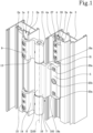
- the hinge according to the invention labelled 100 in its entirety, is of the so-called “three-wing” type and is used for connecting doors or windows.
- the drawings illustrate the hinge 100 for connecting, in use, doors or windows having a fixed frame 1 equipped with a channel 2 with a tubular cross-section partly open and protruding from a surface 1a of the fixed frame 1 and a mobile frame 3 equipped with a channel 4 with a tubular cross-section partly open and protruding from a surface 3a of the mobile frame 3.
- the fixed frame 1 and the mobile frame 3 have a corresponding channel 2 and 4 with a tubular cross-section open towards the outside formed by two protruding wings 2a, 4a with an inverted L-shaped cross-section and opposite one other.
- the hinge 100 comprises a first hinge body comprising a fixing plate 5 which can be positioned, in use, at a zone of the channel 2 or 4 of a mobile or fixed frame 3 or 1.
- the first hinge body is equipped with a device 6 configured for stabilising the plate 5 against the channel 2 or 4.
- a connecting wing 7 ending with a cylindrical portion 8 extends from the fixing plate 5.
- the hinge 100 comprises a second hinge body comprising at least one further plate 9, 10 which can be positioned, in use, at a zone of the channel 2 or 4 of the fixed frame 1 or mobile frame 3 and equipped with a relative device 11, 12 configured to stabilise the plate 9, 10 against the channel 2 or 4.
- a pair of connecting wings 13 and 14 ending with a relative cylindrical portion 15, 16 extend from the at least one plate 9, 10.
- the second hinge body comprises a separate pair of plates 9, 10 which can be positioned, in use, at a zone of the channel 2 or 4 of the fixed frame 1 or mobile frame 3 and equipped with a respective device 11, 12 for stably clamping the plates 9, 10 to the channel 2 or 4.
- a pair of connecting wings 13 and 14 ending with a cylindrical portion 15, 16 extend from each plate 9, 10.
- the two separate plates 9, 10 are positioned at a certain distance from each other along the common channel 2 or 4 in such a way as to be positioned, in use, with the relative cylindrical portions 15 and 16 at the respective ends of the cylindrical portion 8 of the first hinge body.
- the hinge 100 also comprises a common rotation pin 17 housed inside the three cylindrical portions 8, 15 and 16 to define an axis Z100 of rotation of the mobile frame 3.
- the first hinge body is associated with the mobile frame 3, whilst the second hinge body is associated with the fixed frame 1.
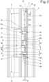
- the first hinge body comprises the fixing plate 5 equipped with at least two through seats 18, 19 engaged by a corresponding fixing element 20 and a third threaded through seat 21.
- the first hinge body also has the stabilising device 6 comprising a counter plate 22 housed inside the channel 4 and having a pair of holes 23, 24 which can be engaged by the fixing element 20 for connecting the plate 5 to the counter plate 22 with the interposition of a front surface of the channel 2 or 4.
- the counter plate 22 has a threaded grub screw 25 protruding at least partly, in use, outside the channel 4.
- the threaded grub screw 25 is rotatably constrained in a hole 26 made in the counter plate 22, and screwably coupled in the third threaded seat 21 of the plate 5 in such a way as to allow an adjustment, in both directions and along an axis X perpendicular to the axis Z100 of rotation, of the distance D of the first hinge body relative to the front surface of the channel 4.
- the front surface of the wings 2, 4 is the one furthest from (and parallel to) the corresponding surface 1a, 3a of the fixed frame 1 and of the mobile frame 3 which thus defines the font surface or contact surface for the plate 5 of the first hinge body and for the two plates 9, 10 of the second hinge body.
- the pair of seats 18 and 19 of the plate 5 for housing the fixing elements 20 each have a first inlet portion 18a, 19a having a first diameter D1 and a second outlet portion 18b, 19b with a second diameter D2 less than the first diameter D1.
- each fixing element 20 comprises a screw having a rod 20a at least partly threaded passing, in use, through the second outlet portion 18b, 19b of the seat 18, 19 of the plate 5 and screwably coupled in the relative hole 23, 24 of the counter plate 22, and an operating head 20b, having a diameter D3 greater than a diameter D4 of the rod 20a, housed, in use, in the inlet portion 18a, 19a of the seat 18, 19 of the plate 5 in such a way as to allow, with the plate 5 fixed, a free sliding for adjustment of the plate 5 of the first hinge body.
- the possibility of adjusting the plate 5 is due to the fact that the inlet portion 18a, 19a of the holes 18, 19 of the plate 5 has a depth greater than the thickness of the relative operating head 20b.
- the rod 20a at least partly threaded of each screw has a length such that it allows, once constrained in the hole 23 or 24 of the counter plate 22, the head 20b to be left in position at a certain distance from the bottom of the inlet portion 18a, 19a in such a way as to allow the free movement for adjustment of the plate 5 along the axis X also with the plate 5 fixed.
- the rod 20a may be divided into a threaded end portion with a diameter less than the diameter D4 of the remaining central portion of the rod (integral with the head 20b) which is not threaded.
- the threaded grub screw 25 comprises a first part composed of a pin 25a having a first diameter D5 axially constrained, but with the possibility of rotating about its axis (for example by pressing the end of the pin 25a), in the cavity 26 of the counter plate 22, and a second threaded portion 25b, having a second diameter D6 greater than the first diameter D5 of the pin 25a, coupled, in use, in the third threaded seat 21 of the fixing plate 5.
- the plate 5 may be moved towards or away from the front surface of the channel in order to be able to adjust the correct distance between the two frames 1 and 3.
- the hinge 100 comprises a reference and adjustment unit 27 along a vertical axis Z1, parallel to the axis Z100 of rotation, between the hinge 100 and the mobile frame 3.
- the reference and adjustment unit 27 is positioned, in use, in the tubular channel 4.
- the reference and adjustment unit 27 is also equipped with a first fixing portion 27a which can be stably coupled in the tubular channel 4 of the mobile frame 3.
- the reference and adjustment unit 27 has the first portion 27a configured to be coupled, by sliding or by a front snap-on connection, in the tubular channel 4 of the mobile frame 2 in which the fixing counter plate 22 is inserted.
- the reference and adjustment unit 27 also has fixing means 28 to stabilise its position in the channel 4 in such a way as to define, with a relative end, a reference point at a height for the plate 5 of the first hinge body, by the stable contact with an end of the counter plate 22.
- the reference unit 27 has a second portion 29 outside the tubular channel 4 equipped with means 30 for adjusting the position adopted by the counter plate 22 and configured for modifying the relative position between the hinge 100, already fixed, and the mobile frame 3 and along the tubular channel 4 by a pushing or a release on a point of contact with the counter plate 22.
- the counter plate 22 is equipped with at least one transversal wing 31 made at a relative end and protruding from the channel 4 in such a way as to define, in use, the point of contact with the adjustment means 30.
- the adjustment means 30 may comprise a screw housed longitudinally along the second portion 29 (in a relative corresponding open seat).
- the screw has a first end with an operating head (to allow its rotation) and a second flat end for contact with the contact wing 31 of the counter plate.
- the weight of the mobile frame 3 allows, once the hinge 100 is mounted and fixed, the flat end of the screw to be maintained in contact with the wing 31 and to be able to push it to lift the mobile frame 3 or to release it to lower the mobile frame 3 with respect to the position of the hinge 100 and therefore of the fixed frame 1.
- the adjustment in height of the mobile frame 3 can be performed without having to loosen any of the fixing screws of the hinge 100.
- a hinge structured in this way achieves the preset aims thanks to a system for fixing to the channel of the first hinge body to the mobile frame which is extremely secure and precise, but provided with adjustment both along an axis perpendicular to the axis of rotation and along an axis parallel to the axis of rotation with the hinge already mounted and fixed.
- This structure allows quick and easy coupling to the mobile frame removed with the possibility of positioning the hinge precisely.
- the fixing unit structure guarantees reliability over time of the mobile structure and, if necessary, convenient adjustment and without the need for loosening the components, thus making the entire structure very safe.
Landscapes
- Engineering & Computer Science (AREA)
- Mechanical Engineering (AREA)
- Hinges (AREA)
Applications Claiming Priority (1)
| Application Number | Priority Date | Filing Date | Title |
|---|---|---|---|
| IT102023000009669A IT202300009669A1 (it) | 2023-05-15 | 2023-05-15 | Cerniera per porta o finestra. |
Publications (1)
| Publication Number | Publication Date |
|---|---|
| EP4464862A1 true EP4464862A1 (fr) | 2024-11-20 |
Family
ID=87136662
Family Applications (1)
| Application Number | Title | Priority Date | Filing Date |
|---|---|---|---|
| EP24174755.9A Pending EP4464862A1 (fr) | 2023-05-15 | 2024-05-08 | Charnière pour porte ou fenêtre |
Country Status (2)
| Country | Link |
|---|---|
| EP (1) | EP4464862A1 (fr) |
| IT (1) | IT202300009669A1 (fr) |
Citations (3)
| Publication number | Priority date | Publication date | Assignee | Title |
|---|---|---|---|---|
| EP1619336A2 (fr) * | 2004-07-22 | 2006-01-25 | Dr. Hahn GmbH & Co. KG | Charnière réglable pour fenêtres, portes ou similaires |
| WO2008052611A1 (fr) * | 2006-10-30 | 2008-05-08 | Dr. Hahn Gmbh & Co. Kg | Ensemble de ferrure pour portes, fenêtres ou analogues |
| WO2008155192A1 (fr) * | 2007-06-20 | 2008-12-24 | Sfs Intec Holding Ag | Charnière de porte ou de fenêtre |
-
2023
- 2023-05-15 IT IT102023000009669A patent/IT202300009669A1/it unknown
-
2024
- 2024-05-08 EP EP24174755.9A patent/EP4464862A1/fr active Pending
Patent Citations (3)
| Publication number | Priority date | Publication date | Assignee | Title |
|---|---|---|---|---|
| EP1619336A2 (fr) * | 2004-07-22 | 2006-01-25 | Dr. Hahn GmbH & Co. KG | Charnière réglable pour fenêtres, portes ou similaires |
| WO2008052611A1 (fr) * | 2006-10-30 | 2008-05-08 | Dr. Hahn Gmbh & Co. Kg | Ensemble de ferrure pour portes, fenêtres ou analogues |
| WO2008155192A1 (fr) * | 2007-06-20 | 2008-12-24 | Sfs Intec Holding Ag | Charnière de porte ou de fenêtre |
Also Published As
| Publication number | Publication date |
|---|---|
| IT202300009669A1 (it) | 2024-11-15 |
Similar Documents
| Publication | Publication Date | Title |
|---|---|---|
| EP0992647B1 (fr) | Charnière réglable pour cadre de porte | |
| US5483770A (en) | Door or window mountings | |
| US6643896B2 (en) | Adjustable hinge | |
| US3867790A (en) | Stay arrangement for a window or door of the turn-and-tilt type | |
| KR102147567B1 (ko) | 도어용 힌지조립체 | |
| EP2333212A1 (fr) | Charnière à déclic réglable pour portes et volets, notamment en verre trempé | |
| EP4464862A1 (fr) | Charnière pour porte ou fenêtre | |
| US4763445A (en) | Combined slide guide and pivot pin for sash window | |
| GB2309477A (en) | Roller unit for a sliding wing, with adjustable height mechanism. | |
| EP3461981A1 (fr) | Dispositif de réglage pour régler la position de la vitre de fenêtre d'un lève-vitre de véhicule automobile | |
| US10927580B2 (en) | Door closers | |
| EP3757322B1 (fr) | Charnière cachée réglable | |
| EP4124712A1 (fr) | Charnière pour porte ou fenêtre et procédé d'assemblage de la charnière sur une porte ou une fenêtre | |
| US20070240283A1 (en) | Hinged for doors or windows | |
| EP1061219A1 (fr) | Charnière pour cadres | |
| GB2270105A (en) | Wing frame locking arrangement | |
| KR102532350B1 (ko) | 여닫이용 하부 힌지장치 | |
| EP2495383A2 (fr) | Frein coulissant pour fenêtres pivotantes, portes ou volets | |
| EP2924211A1 (fr) | Charnière ajustable pour portes ou fenêtres | |
| US6823626B2 (en) | Window sash tilt control | |
| EP1997991A2 (fr) | Charnière pour portes ou fenêtres | |
| EP3942135B1 (fr) | Charnière pour portes ou fenêtres | |
| EP3971377B1 (fr) | Charnière, ensemble châssis-vitrage pour fermer une ouverture et processus de réglage d'un ensemble châssis-vitrage | |
| EP2189604A1 (fr) | Pince et support perfectionnés permettant de fixer des vitres à un dispositif destiné à des fenêtres d'automobiles | |
| CN221400191U (zh) | 一种可上下调节的推窗铰链结构 |
Legal Events
| Date | Code | Title | Description |
|---|---|---|---|
| PUAI | Public reference made under article 153(3) epc to a published international application that has entered the european phase |
Free format text: ORIGINAL CODE: 0009012 |
|
| STAA | Information on the status of an ep patent application or granted ep patent |
Free format text: STATUS: THE APPLICATION HAS BEEN PUBLISHED |
|
| AK | Designated contracting states |
Kind code of ref document: A1 Designated state(s): AL AT BE BG CH CY CZ DE DK EE ES FI FR GB GR HR HU IE IS IT LI LT LU LV MC ME MK MT NL NO PL PT RO RS SE SI SK SM TR |
|
| STAA | Information on the status of an ep patent application or granted ep patent |
Free format text: STATUS: REQUEST FOR EXAMINATION WAS MADE |
|
| 17P | Request for examination filed |
Effective date: 20250515 |
|
| STAA | Information on the status of an ep patent application or granted ep patent |
Free format text: STATUS: EXAMINATION IS IN PROGRESS |
|
| 17Q | First examination report despatched |
Effective date: 20251201 |