EP4464885A1 - Dispositif de commande pour engin de chantier et engin de chantier équipé de celui-ci - Google Patents
Dispositif de commande pour engin de chantier et engin de chantier équipé de celui-ci Download PDFInfo
- Publication number
- EP4464885A1 EP4464885A1 EP23766475.0A EP23766475A EP4464885A1 EP 4464885 A1 EP4464885 A1 EP 4464885A1 EP 23766475 A EP23766475 A EP 23766475A EP 4464885 A1 EP4464885 A1 EP 4464885A1
- Authority
- EP
- European Patent Office
- Prior art keywords
- rotational speed
- engine
- control
- hydraulic pump
- construction machine
- Prior art date
- Legal status (The legal status is an assumption and is not a legal conclusion. Google has not performed a legal analysis and makes no representation as to the accuracy of the status listed.)
- Pending
Links
Images

Classifications
-
- E—FIXED CONSTRUCTIONS
- E02—HYDRAULIC ENGINEERING; FOUNDATIONS; SOIL SHIFTING
- E02F—DREDGING; SOIL-SHIFTING
- E02F9/00—Component parts of dredgers or soil-shifting machines, not restricted to one of the kinds covered by groups E02F3/00 - E02F7/00
- E02F9/20—Drives; Control devices
- E02F9/22—Hydraulic or pneumatic drives
- E02F9/2246—Control of prime movers, e.g. depending on the hydraulic load of work tools
-
- E—FIXED CONSTRUCTIONS
- E02—HYDRAULIC ENGINEERING; FOUNDATIONS; SOIL SHIFTING
- E02F—DREDGING; SOIL-SHIFTING
- E02F9/00—Component parts of dredgers or soil-shifting machines, not restricted to one of the kinds covered by groups E02F3/00 - E02F7/00
- E02F9/20—Drives; Control devices
- E02F9/22—Hydraulic or pneumatic drives
- E02F9/2221—Control of flow rate; Load sensing arrangements
- E02F9/2232—Control of flow rate; Load sensing arrangements using one or more variable displacement pumps
- E02F9/2235—Control of flow rate; Load sensing arrangements using one or more variable displacement pumps including an electronic controller
-
- E—FIXED CONSTRUCTIONS
- E02—HYDRAULIC ENGINEERING; FOUNDATIONS; SOIL SHIFTING
- E02F—DREDGING; SOIL-SHIFTING
- E02F9/00—Component parts of dredgers or soil-shifting machines, not restricted to one of the kinds covered by groups E02F3/00 - E02F7/00
- E02F9/20—Drives; Control devices
- E02F9/22—Hydraulic or pneumatic drives
- E02F9/2278—Hydraulic circuits
- E02F9/2296—Systems with a variable displacement pump
-
- F—MECHANICAL ENGINEERING; LIGHTING; HEATING; WEAPONS; BLASTING
- F02—COMBUSTION ENGINES; HOT-GAS OR COMBUSTION-PRODUCT ENGINE PLANTS
- F02D—CONTROLLING COMBUSTION ENGINES
- F02D29/00—Controlling engines, such controlling being peculiar to the devices driven thereby, the devices being other than parts or accessories essential to engine operation, e.g. controlling of engines by signals external thereto
-
- E—FIXED CONSTRUCTIONS
- E02—HYDRAULIC ENGINEERING; FOUNDATIONS; SOIL SHIFTING
- E02F—DREDGING; SOIL-SHIFTING
- E02F9/00—Component parts of dredgers or soil-shifting machines, not restricted to one of the kinds covered by groups E02F3/00 - E02F7/00
- E02F9/20—Drives; Control devices
- E02F9/22—Hydraulic or pneumatic drives
- E02F9/2278—Hydraulic circuits
- E02F9/2285—Pilot-operated systems
-
- E—FIXED CONSTRUCTIONS
- E02—HYDRAULIC ENGINEERING; FOUNDATIONS; SOIL SHIFTING
- E02F—DREDGING; SOIL-SHIFTING
- E02F9/00—Component parts of dredgers or soil-shifting machines, not restricted to one of the kinds covered by groups E02F3/00 - E02F7/00
- E02F9/20—Drives; Control devices
- E02F9/22—Hydraulic or pneumatic drives
- E02F9/2278—Hydraulic circuits
- E02F9/2292—Systems with two or more pumps
-
- F—MECHANICAL ENGINEERING; LIGHTING; HEATING; WEAPONS; BLASTING
- F02—COMBUSTION ENGINES; HOT-GAS OR COMBUSTION-PRODUCT ENGINE PLANTS
- F02D—CONTROLLING COMBUSTION ENGINES
- F02D41/00—Electrical control of supply of combustible mixture or its constituents
- F02D41/02—Circuit arrangements for generating control signals
- F02D41/14—Introducing closed-loop corrections
- F02D41/1401—Introducing closed-loop corrections characterised by the control or regulation method
- F02D2041/1433—Introducing closed-loop corrections characterised by the control or regulation method using a model or simulation of the system
Definitions
- the present invention relates to a control device for a construction machine and a construction machine including the control device.
- a conventionally known construction machine includes an engine, a hydraulic pump that is caused by a driving force of the engine to discharge hydraulic oil, and an actuator that is driven by receiving supply of the hydraulic oil from the hydraulic pump.
- the engine is rotationally driven to achieve a target rotational speed.
- the hydraulic pump receives a command value of a discharge amount (tilting command) and is driven to achieve the discharge amount.
- the hydraulic pump and the engine are connected via a joint device such as a coupling.
- Patent Literature 1 discloses an engine control technique in which feedforward control and feedback control are combined to improve the operability in such a construction machine.
- the engine control device includes a required load calculation means that calculates, as a required load, an engine output necessary for driving the hydraulic pump in accordance with the actuation of the actuator, and an engine controller.
- the engine controller includes a feedforward control means that adds a fuel injection increase amount set in advance in accordance with the required load to a fuel injection amount of the engine when the required load is calculated by the required load calculation means, and an injection amount correction means that, when the fuel injection amount is increased by the feedforward control means, decreases to correct the fuel injection increase amount set in advance in a case where a deviation between a peak value of an actual rotational speed and a target rotational speed exceeds a predetermined determination threshold.
- Patent Literature 1 JP 2014-125949 A
- An object of the present invention is to provide a control device for a construction machine, the control device being capable of statically determining a rotational speed of an engine at an early stage, and a construction machine including the control device.
- the present invention provides a control device for a construction machine including an engine, an engine controller that controls the engine in accordance with a rotational speed command signal, a variable displacement hydraulic pump that is driven by the engine and discharges hydraulic oil, and an actuator that is actuated by receiving supply of the hydraulic oil from the hydraulic pump.
- the control device includes a rotational speed detection unit that detects a rotational speed of the engine, and a control unit that corrects an input target rotational speed of the engine and inputs the corrected target rotational speed to the engine controller as the rotational speed command signal.
- the control unit can execute each of feedforward control and feedback control.
- the control unit calculates a load torque speed of the engine based on a discharge amount commanded for the hydraulic pump, and corrects the target rotational speed in accordance with at least the load torque speed.
- the control unit corrects the target rotational speed in accordance with a deviation between the target rotational speed and the rotational speed detected by the rotational speed detection unit.
- the load torque speed is a temporal change in the load torque applied to the engine.
- the present invention also provides a construction machine.
- the construction machine includes an engine, a variable displacement hydraulic pump that is driven by the engine and discharges hydraulic oil, an actuator that is actuated by receiving the hydraulic oil discharged from the hydraulic pump, and the control device for the construction machine described above that controls the rotational speed of the engine.
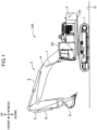
- FIG. 1 illustrates a hydraulic excavator 100 (construction machine) on which an engine control device 100A ( FIG. 2 ) is mounted according to one embodiment of the present invention.
- the hydraulic excavator 100 includes a crawler-type lower travelling body 1 that can travel on a traveling surface, an upper slewing body 2 (machine body) mounted on the lower travelling body 1 so as to be able to slew around a slewing center axis perpendicular to the traveling surface, and a work attachment 3 mounted on the upper slewing body 2.
- the work attachment 3 includes a boom 4 derrickably supported by the upper slewing body 2, an arm 5 rotatably connected to a distal end of the boom 4, and a bucket 6 rotatably connected to a distal end of the arm 5.
- the upper slewing body 2 includes a slewing frame 2S and a cab 2A.
- the hydraulic excavator 100 further includes a boom cylinder 7 that is actuated to cause the boom 4 to make a derricking movement with respect to the upper slewing body 2, an arm cylinder 8 that is actuated to cause the arm 5 to make a rotating movement with respect to the boom 4, and a bucket cylinder 9 that is actuated to cause the bucket 6 to make a rotating movement with respect to the arm 5.
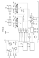
- FIG. 2 is a hydraulic circuit diagram of the engine control device 100A (control device) according to the present embodiment.
- the engine control device 100A includes a first hydraulic pump 11 (hydraulic pump) and a second hydraulic pump 12 connected to the engine 10, a first pump pressure sensor 11P, a second pump pressure sensor 12P, a tank T, a pilot pump 20, the boom cylinder 7, the arm cylinder 8, a boom control valve 15, an arm control valve 16, a first valve proportional valve 21, a second valve proportional valve 22, a third valve proportional valve 23, a fourth valve proportional valve 24, a lever lock valve 25, an operation unit 30, a control unit 50, and an engine control unit (ECU) 55.
- FIG. 2 illustration of the bucket cylinder 9, a slewing motor disposed in the slewing frame 2S, and a hydraulic circuit related thereto is omitted.
- the engine 10 In response to the fuel injection command signal, the engine 10 is rotated by injection of fuel of a fuel injection amount corresponding to the signal, and generates a driving force.
- the engine 10 includes an engine rotational speed sensor 101 (rotational speed detection unit) and a supercharging pressure sensor 102.
- the engine rotational speed sensor 101 detects the rotational speed of the engine 10 and inputs a signal corresponding to the detection result to the control unit 50.
- the supercharging pressure sensor 102 detects the supercharging pressure of the engine 10 and inputs a signal corresponding to the detection result to the control unit 50.
- the first hydraulic pump 11 mainly discharges hydraulic oil for actuating the boom cylinder 7.
- the second hydraulic pump 12 discharges hydraulic oil for actuating the arm cylinder 8.
- the pilot pump 20 supplies pilot oil to each valve proportional valve.
- the first hydraulic pump 11, the second hydraulic pump 12, and the pilot pump 20 are connected to an output shaft of the engine 10 via a coupling joint, and are driven by the engine 10. Note that in FIG. 2 , the connection between the engine 10 and the pilot pump 20 is not illustrated.
- the first hydraulic pump 11 and the second hydraulic pump 12 are variable displacement hydraulic pumps.
- the first hydraulic pump 11 includes a first pump proportional valve 111
- the second hydraulic pump 12 includes a second hydraulic pump proportional valve 121. These proportional valves are opened in response to command signals received from the control unit 50 to adjust the discharge amounts (tilt) of the first hydraulic pump 11 and the second hydraulic pump 12.
- the first pump pressure sensor 11P pressure detection unit detects a pump pressure of the first hydraulic pump 11 (pressure of the hydraulic oil discharged from the first hydraulic pump 11).
- the second pump pressure sensor 12P detects a pump pressure of the second hydraulic pump 12 (pressure of the hydraulic oil discharged from the second hydraulic pump 12). Signals corresponding to the pump pressures detected by these pump pressure sensors are input to the control unit 50.
- the boom cylinder 7 is an actuator that is actuated to cause the boom 4 to make a boom lowering motion and a boom raising motion upon reception of the supply of the hydraulic oil discharged from the first hydraulic pump 11.
- the boom cylinder 7 includes a cylinder body and a piston rod that includes a partition portion (piston portion) partitioning the cylinder body into a head chamber and a rod chamber and is movable relative to the cylinder body.
- the boom cylinder 7 can be extended so as to cause the boom 4 to make the boom raising motion upon reception of the hydraulic oil discharged from the first hydraulic pump 11 into the head chamber, and can be contracted so as to cause the boom 4 to make the boom lowering motion upon reception of the hydraulic oil discharged from the first hydraulic pump 11 into the rod chamber.
- the arm cylinder 8 is an actuator that is actuated to cause the arm 5 to make an arm pushing motion and an arm pulling motion upon reception of supply of the hydraulic oil discharged from the second hydraulic pump 12.
- the arm cylinder 8 also includes a cylinder body and a piston rod that includes a partition portion (piston portion) partitioning the cylinder body into a head chamber and a rod chamber and is movable relative to the cylinder body.
- a boom motion detection sensor 7S is attached to the boom cylinder 7, and an arm motion detection sensor 8S is attached to the arm cylinder 8.
- the boom motion detection sensor 7S detects a telescopic stroke of the boom cylinder 7 to be able to detect a driving state of the boom 4.
- the arm motion detection sensor 8S detects a telescopic stroke of the arm cylinder 8 to be able to detect a driving state of the arm 5.
- the boom motion detection sensor 7S and the arm motion detection sensor 8S are stroke sensors, but may be angle sensors that detect angles of the boom 4 and the arm 5 in another embodiment.
- the boom control valve 15 is disposed between the first hydraulic pump 11 and the boom cylinder 7, and opens and closes to change the flow rate of the hydraulic oil supplied from the first hydraulic pump 11 to the boom cylinder 7.
- the boom control valve 15 is a pilot-operated three-position direction switching valve having a boom lowering pilot port 151 and a boom raising pilot port 152.
- the boom control valve 15 is maintained at a neutral position P2 when no pilot pressure is input to the boom lowering pilot port 151 and the boom raising pilot port 152, and blocks between the first hydraulic pump 11 and the boom cylinder 7. Note that a relief valve, not illustrated, is disposed between the first hydraulic pump 11 and the boom control valve 15.
- the boom control valve 15 When a boom lowering pilot pressure is input into the boom lowering pilot port 151, the boom control valve 15 is switched from the neutral position P2 to a boom lowering position P1 with a stroke corresponding to the magnitude of the boom lowering pilot pressure. This causes the valve to be opened to allow the hydraulic oil to be supplied from the first hydraulic pump 11 to the rod chamber of the boom cylinder 7 at a flow rate corresponding to the stroke and allow the hydraulic oil to be discharged from the head chamber of the boom cylinder 7. This causes the boom cylinder 7 to be driven in the boom lowering direction at a speed corresponding to the boom lowering pilot pressure.
- the boom control valve 15 When a boom raising pilot pressure is input into the boom raising pilot port 152, the boom control valve 15 is switched from the neutral position P2 to a boom raising position P3 with a stroke corresponding to the magnitude of the boom raising pilot pressure. This causes the boom control valve 15 to be opened to allow the hydraulic oil to be supplied from the first hydraulic pump 11 to the head chamber of the boom cylinder 7 at the flow rate corresponding to the stroke, and allow the hydraulic oil to be discharged from the rod chamber of the boom cylinder 7. This causes the boom cylinder 7 to be driven in the boom raising direction at a speed corresponding to the boom raising pilot pressure.
- the arm control valve 16 is disposed between the second hydraulic pump 12 and the arm cylinder 8, and opens and closes to change the flow rate of the hydraulic oil supplied from the second hydraulic pump 12 to the arm cylinder 8.
- the arm control valve 16 is a pilot-operated three-position direction switching valve having an arm pushing pilot port 161 and an arm pulling pilot port 162.
- the arm control valve 16 is maintained at a neutral position P5 when no pilot pressure is input to the arm pushing pilot port 161 and the arm pulling pilot port 162, and blocks between the second hydraulic pump 12 and the arm cylinder 8. Note that a relief valve, not illustrated, is disposed between the second hydraulic pump 12 and the arm control valve 16.
- the arm control valve 16 When an arm pushing pilot pressure is input into the arm pushing pilot port 161, the arm control valve 16 is switched from the neutral position P5 to an arm pushing position P4 with a stroke corresponding to the magnitude of the arm pushing pilot pressure. This causes the arm control valve 16 to be opened to allow the hydraulic oil to be supplied from the second hydraulic pump 12 to the rod chamber of the arm cylinder 8 at a flow rate corresponding to the stroke, and allow the hydraulic oil to be returned from the head chamber of the arm cylinder 8 to the tank. This causes the arm cylinder 8 to be driven in the arm pushing direction at a speed corresponding to the arm pushing pilot pressure.
- the arm control valve 16 When an arm pulling pilot pressure is input into the arm pulling pilot port 162, the arm control valve 16 is switched from the neutral position P5 to an arm pulling position P6 with a stroke corresponding to the magnitude of the arm pulling pilot pressure. This causes the valve to be opened to allow the hydraulic oil to be supplied from the second hydraulic pump 12 to the head chamber of the arm cylinder 8 at a flow rate corresponding to the stroke, and allow the hydraulic oil to be returned from the rod chamber of the arm cylinder 8 to the tank. This causes the arm cylinder 8 to be driven in the arm pulling direction at a speed corresponding to the arm pulling pilot pressure.
- the operation unit 30 is disposed in the cab 2A and receives various operations for actuating the hydraulic excavator 100 from the operator.
- the operation unit 30 includes a boom operation unit 31, an arm operation unit 32, a dial switch 33, and a lever lock switch 34.
- the boom operation unit 31 receives a boom lowering operation and a boom raising operation for causing the boom 4 to make the boom lowering motion and the boom raising motion, respectively.
- the boom operation unit 31 includes a boom operation lever 31A that receives an operation for driving the boom cylinder 7 and a boom command output unit 31B.
- the boom operation lever 31A is a member that can rotationally move in response to the boom lowering operation and the boom raising operation by the operator.
- the boom lowering operation and the boom raising operation are operations for rotationally moving the boom operation lever 31A in opposite directions.
- the boom command output unit 31B inputs a command signal corresponding to the operation to the control unit 50 in conjunction with the boom raising operation and the boom lowering operation given to the boom operation lever 31A.
- the command signal includes information corresponding to an operation direction and an operation amount of the boom operation lever 31A.
- the arm operation unit 32 receives an arm pushing operation and an arm pulling operation for causing the arm 5 to make the arm pushing motion and the arm pulling motion, respectively.
- the arm operation unit 32 includes an arm operation lever 32A that receives an operation for driving the arm cylinder 8 and an arm command output unit 32B.
- the arm operation lever 32A is a member that can rotationally move in response to the arm pushing operation and the arm pulling operation by the operator.
- the arm pushing operation and the arm pulling operation are operations for rotationally moving the arm operation lever 32A in opposite directions.
- the arm command output unit 32B inputs a command signal corresponding to the operation to the control unit 50 in conjunction with one of the arm pushing operation and the arm pulling operation given to the arm operation lever 32A.
- the command signal includes information corresponding to an operation direction and an operation amount of the arm operation lever 32A.
- the dial switch 33 receives an input of a target rotational speed of the engine 10.
- the dial switch 33 is a rotatable dial, and is operated (rotated) by the operator to set the target rotational speed of the engine 10.
- the dial switch 33 includes an operation amount transmission unit (not illustrated). In the operation amount transmission unit, when the operator rotates the dial switch 33 to set the target rotational speed, a signal (an operation amount signal or a rotational speed signal) corresponding to the target rotational speed is input to the control unit 50.
- the lever lock switch 34 is a switch for switching between supply and shut-off of pilot oil to the boom control valve 15 and the arm control valve 16.
- a command signal (drive signal) is input to the lever lock valve 25 so as to allow supply of pilot oil to the first valve proportional valve 21, the second valve proportional valve 22, the third valve proportional valve 23, and the fourth valve proportional valve 24.
- a command signal is input to the lever lock valve 25 so as to prevent the supply of the pilot oil to the first valve proportional valve 21, the second valve proportional valve 22, the third valve proportional valve 23, and the fourth valve proportional valve 24.
- the first valve proportional valve 21 and the second valve proportional valve 22 are actuated to allow the pilot pressure corresponding to the operation input to the boom operation lever 31A of the boom operation unit 31 to be input from the pilot pump 20 to the boom control valve 15.
- the third valve proportional valve 23 and the fourth valve proportional valve 24 open to allow the pilot pressure corresponding to the operation input to the arm operation lever 32A of the arm operation unit 32 to be input from the pilot pump 20 to the arm control valve 16.
- the boom operation unit 31 and the arm operation unit 32 each may include a remote control valve, and directly adjust the pilot pressures of the boom control valve 15 and the arm control valve 16 in accordance with the operation amounts received by the boom operation lever 31A and the arm operation lever 32A, respectively. Further, each lever may be an electric lever.
- the lever lock valve 25 is disposed so as to be interposed between the pilot pump 20 and each valve proportional valve.
- the lever lock valve 25 is opened by receiving a signal (lock release signal) corresponding to the state of the lever lock switch 34 from the control unit 50, and is switched between a state in which supply of the pilot oil to each valve proportional valve is allowed and a state in which the supply is cut off.
- FIG. 3 is a block diagram of the control unit 50 of the engine control device 100A according to the present embodiment.
- the control unit 50 includes a central processing unit (CPU), a read only memory (ROM) that stores a control program, a random access memory (RAM) used as a work area for the CPU, and the like.
- the control unit 50 functions to include functional units including a calculation unit 501, a determination unit 502, and a storage unit 503 by the CPU executing a control program stored in the ROM. These functional units have no substance and correspond to units of functions executed by the control program. Note that an entire or a part of the control unit 50 is not required to be provided in the hydraulic excavator 100, and may be disposed at a position different from the hydraulic excavator 100 in a case where the hydraulic excavator 100 is remotely controlled.
- control program may be transmitted from a server (management device), a cloud, or the like at a remote location to the control unit 50 in the hydraulic excavator 100 and executed, or the control program may be executed on the server or the cloud, and generated various command signals may be transmitted to the hydraulic excavator 100.
- the calculation unit 501 executes calculation processing required in various types of processing executed by the control unit 50.
- the determination unit 502 executes determination processing required in various types of processing executed by the control unit 50.
- the storage unit 503 stores parameters and thresholds required in various processing executed by the control unit 50.
- control unit 50 receives various signals from the boom operation lever 31A, the arm operation lever 32A, the dial switch 33, the lever lock switch 34, the engine rotational speed sensor 101, the supercharging pressure sensor 102, the first pump pressure sensor 11P, the second pump pressure sensor 12P, the boom motion detection sensor 7S, and the arm motion detection sensor 8S. Furthermore, the control unit 50 inputs various command signals to the ECU 55, the first pump proportional valve 111, the second hydraulic pump proportional valve 121, the first valve proportional valve 21, the second valve proportional valve 22, the third valve proportional valve 23, the fourth valve proportional valve 24, and the lever lock valve 25.
- control unit 50 converts an operation lever amount signal received from the operation unit 30 into a target pump discharge command signal, and inputs the target pump discharge command signal to the first pump proportional valve 111 and the second hydraulic pump proportional valve 121. Further, the control unit 50 converts an operation lever amount signal received from the operation unit 30 into a target valve spool stroke amount command signal, and inputs the target valve spool stroke amount command signal to the first valve proportional valve 21, the second valve proportional valve 22, the third valve proportional valve 23, and the fourth valve proportional valve 24. Further, the control unit 50 converts a dial switch operation amount received by the dial switch 33 into a target engine rotational speed command signal.
- the engine control unit (ECU) 55 receives a rotational speed command signal (command signal) from the control unit 50, and causes the engine 10 to be rotated at a predetermined actual rotational speed with a fuel injection amount in accordance with the rotational speed command signal.
- command signal a rotational speed command signal
- the control unit 50 can execute the feedforward control and the feedback control.
- the control unit 50 determines discharge amounts Q (discharge amount commands) of the first hydraulic pump 11 and the second hydraulic pump 12 in accordance with the operation amount of the operation input to the operation unit 30, calculates a load torque speed Trs, which is a temporal change of a load torque Tr applied to the engine 10, based on the discharge amounts Q, the rotational speed Nr detected by the engine rotational speed sensor 101, and the pump pressures P detected respectively by the first pump pressure sensor 11P and the second pump pressure sensor 12P, and sets a correction value of the target rotational speed of the engine 10 in accordance with at least the load torque speed.
- control unit 50 sets the correction value of the target rotational speed of the engine 10 in accordance with the deviation between the target rotational speed Nd (rotational speed command) input through the dial switch 33 and the rotational speed Nr detected by the engine rotational speed sensor 101.
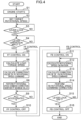
- FIG. 4 is a flowchart illustrating engine control processing executed by the control unit 50 in the engine control device 100A according to the present embodiment.
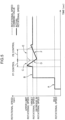
- FIG. 5 is a graph illustrating progression of the engine rotational speed in the hydraulic excavator 100 including the engine control device 100A. Note that in FIG. 5 , the rotational speed command value to the ECU 55 is indicated by a broken line in the graph, and an actual rotational speed of the engine 10 is indicated by a solid line in the graph.
- FIG. 5 the rotational speed command value to the ECU 55 is indicated by a broken line in the graph, and an actual rotational speed of the engine 10 is indicated by a solid line in the graph.
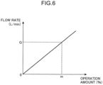
- FIG. 6 is a graph illustrating a relationship between the operation amount of the operation lever and the flow rate of the hydraulic pump in the hydraulic excavator 100 including the engine control device 100A.
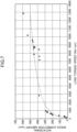
- FIG. 7 is a graph illustrating a relationship between the load torque speed and the rotational speed correction amount of the engine 10 in the hydraulic excavator 100 including the engine control device 100A.
- the engine 10 is started (step S1 in FIG. 4 ).
- the dial switch 33 is set to default setting (Low Idle)
- the lever lock switch 34 is in an OFF state
- the pilot hydraulic circuit is closed by the lever lock valve 25. That is, the operation unit 30 is in a non-operation state.
- the engine 10 rotates at an idle rotational speed.
- step S3 the determination unit 502 of the control unit 50 determines whether the lever lock switch 34 has been operated into an ON state.
- the pilot hydraulic circuit is opened (YES in step S3).
- the determination unit 502 repeats the determination in step S3 until the lever lock switch 34 is set into the ON state.
- the engine 10 in an unloaded state rotates at the target rotational speed (actual rotational speed).
- the determination unit 502 determines whether a lever operation has been input to the boom operation lever 31A of the operation unit 30 (step S4).
- the control unit 50 starts feedforward control (FF control). Note that in a case where no lever operation is input (NO in step S4), the determination unit 502 repeats the determination in step S4.
- a command signal corresponding to the necessary pump tilt q is input to the first pump proportional valve 111 of the first hydraulic pump 11, and the discharge amount (tilt) of the first hydraulic pump 11 is adjusted.
- a command signal is input to the first valve proportional valve 21 or the second valve proportional valve 22 in accordance with the operation amount input to the boom operation lever 31A, and the movement amount (stroke amount) of the spool of the boom control valve 15 is adjusted.
- the calculation unit 501 calculates a latest output torque of the first hydraulic pump 11, that is, the load torque Tr (Nm) based on the following Equation 2 using the necessary pump tilt q calculated based on the Equation 1 and an actual pump pressure P (MPa) (pump pressure) detected by the first pump pressure sensor 11P.
- Tr P ⁇ q 2 ⁇
- the calculation unit 501 differentiates the load torque Tr calculated based on the Equation 2 with respect to a sampling time ⁇ t (sec) as expressed in the following Equation 3 to calculate the load torque speed Trs (Nm/sec).
- Tr s dTr t dt
- the calculation unit 501 determines, using a characteristic value map of FIG. 7 stored in advance in the storage unit 503, a correction value ⁇ Nff of the target rotational speed command of the engine 10 for the load torque speed Trs calculated based on the Equation 3 (step S7).
- the correction value is set so that the correction value ⁇ Nff of the target rotational speed command increases as the calculated load torque speed Trs is higher.
- a regression equation of the graph illustrated in FIG. 7 may be stored in the storage unit 503 in advance, and the calculation unit 501 may calculate the correction value ⁇ Nff based on the regression equation.
- the engine control device 100A can acquire information corresponding to the supercharging pressure detected by the supercharging pressure sensor 102 of the engine 10. Therefore, the storage unit 503 desirably stores a plurality of characteristic value maps in accordance with the supercharging pressure (a plurality of pressure regions) of the engine 10. In a case where the engine 10 is a supercharging type engine, a possible output is determined by the magnitude of the supercharging pressure. Therefore, as described above, by setting the correction value ⁇ Nff in accordance with the supercharging pressure, more stable rotational speed control can be made.
- control unit 50 inputs, to the ECU 55, a command signal in which the correction value ⁇ Nff determined as described above is reflected in the target rotational speed input to the dial switch 33 (step S8: FF rotational speed command correction).
- the ECU 55 corrects the fuel injection amount command value and the like in accordance with the correction amount to increase the actual rotational speed of the engine 10. Note that in the present embodiment, as indicated by an arrow C in FIG. 5 , the control unit 50 inputs a command signal to the ECU 55 so as to maintain the maximum value of the correction value of the target rotational speed for a certain period of time.
- the rotational speed of the engine 10 temporarily decreases as indicated by an arrow D in FIG. 5 due to a rapid increase in the actual load torque immediately after the start of the operation of the boom operation lever 31A.
- the rotational speed command value is maintained in a high state by the feedforward control in advance, a high-fuel injection state is maintained, and the decrease in the rotational speed of the engine 10 can be controlled.
- the determination unit 502 of the control unit 50 determines whether the actuator (ACT), that is, the boom cylinder 7 has been accelerated (step S9). In other words, in response to the discharge command to the first pump proportional valve 111 of the first hydraulic pump 11 and the valve stroke command to the boom control valve 15 described above, a determination is made whether the hydraulic oil has flowed into the boom cylinder 7 and the boom 4 has been driven. In a case where the boom cylinder 7 has been accelerated (YES in step S9), the control unit 50 ends the execution of the feedforward control (step S10), and shifts to the feedback control (FB control) (step S11). Note that in a case where the boom cylinder 7 has not been accelerated in step S9 (NO in step S9), the storage unit 503 repeats the acceleration determination of the boom cylinder 7 in step S9.
- control unit 50 inputs a command signal (correction engine rotational speed command) corresponding to the calculated rotational speed correction value ⁇ Nfb to the ECU 55 (step S14; arrow E in FIG. 5 ).
- the ECU 55 that has received the command signal corrects the fuel injection amount command and the like in accordance with the correction amount, and control is made that the rotational speed of the engine 10 approaches the target rotational speed (arrow F in FIG. 5 ).
- the determination unit 502 of the control unit 50 determines whether the lever lock switch 34 has been switched to the OFF state (step S15).
- the control unit 50 ends the feedforward control (step S16) and ends the engine control of FIG. 4 .
- the control unit 50 repeats the processing in step S12 and subsequent steps. That is, the feedback control continues to be executed so that the deviation between the actual engine rotational speed and the target engine rotational speed becomes zero.
- control unit 50 can execute each of the feedforward control and the feedforward control in response to the operation of the boom operation lever 31A and the action of the load torque associated with the rotation of the first hydraulic pump 11 on the engine 10.
- Such a configuration can cause the feedforward control executed by the control unit 50 to control the rotational speed decrease amount of the engine 10 with respect to the load torque of the first hydraulic pump 11 and can cause the feedback control to statically determine the rotational speed of the engine 10 to the target rotational speed at an early stage.
- the command correction amount in the feedforward control is determined in accordance with the load torque speed
- the optimum rotational speed correction control can be executed while the correction amount is being controlled under the condition that the input speed is slow and the rotational speed decrease amount is small even with the same load torque. Therefore, the rotational speed of the engine 10 can be statically determined early, and the fuel efficiency of the engine 10 can be reduced as compared with the conventional engine control device.
- the pump discharge amount command input to the first pump proportional valve 111 by the control unit 50 does not change with the fluctuation of the engine rotational speed
- the pump discharge command is set in accordance with the operation amount input to the boom operation lever 31A by the operator, and flow rate compensation in accordance with the operation amount is enabled.
- the rotational speed of the engine 10 can be adjusted only by inputting a command signal corresponding to the corrected target rotational speed to the ECU 55.
- the correction control of the rotational speed of the engine 10 does not intervene in control parameters on the ECU 55 side, design change of the engine 10 and the ECU 55 is not required for the rotational speed control, and shortening of a development period and cost reduction are achieved.
- the control unit 50 calculates the load torque speed Trs based on the set pump discharge amount Q, the rotational speed Nr detected by the engine rotational speed sensor 101, and the pump pressure P of the first hydraulic pump 11 detected by the first pump pressure sensor 11P.
- the latest load torque speed can be easily calculated based on the actual rotational speed of the engine 10 and the discharge pressure of the first hydraulic pump 11.
- the engine control device 100A further includes the boom motion detection sensor 7S (actuation detection unit) that detects that the boom cylinder 7 is actuated. Then, in a case where the boom motion detection sensor 7S detects that the boom cylinder 7 is actuated after the boom operation lever 31A receives the operation for driving the boom cylinder 7, the control unit 50 stops the execution of the feedforward control.
- the boom motion detection sensor 7S actuation detection unit
- the correction value is set so that the correction value of the target rotational speed increases as the calculated load torque speed is higher.
- control unit 50 sets the maximum value of the correction value of the target rotational speed of the engine 10 in accordance with the load torque speed, and corrects the target rotational speed so as to maintain the maximum value for a certain period of time.
- the rotational speed command value for the ECU 55 is maintained in a high region, and the rotational speed decrease amount immediately after the generation of the load torque can be further reduced.
- the engine control device 100A further includes the supercharging pressure sensor 102 (supercharging pressure detection unit) that detects the supercharging pressure of the engine 10. Then, in the feedforward control, the control unit 50 corrects the target rotational speed in accordance with the load torque speed and the supercharging pressure detected by the supercharging pressure sensor 102.
- the supercharging pressure sensor 102 supercharging pressure detection unit
- an appropriate correction amount of the target rotational speed can be set in accordance with the supercharging pressure, thus preventing an overshoot (deterioration of fuel efficiency) of the rotational speed due to useless correction during high supercharging.
- the present invention provides a control device for a construction machine including an engine, an engine controller that controls the engine in accordance with a rotational speed command signal, a variable displacement hydraulic pump that is driven by the engine and discharges hydraulic oil, and an actuator that is actuated by receiving supply of the hydraulic oil from the hydraulic pump.
- the control device includes a rotational speed detection unit that detects a rotational speed of the engine, and a control unit that corrects an input target rotational speed of the engine and inputs the corrected target rotational speed to the engine controller as the rotational speed command signal.
- the control unit can execute each of feedforward control and feedback control.
- the control unit calculates a load torque speed of the engine based on a discharge amount commanded for the hydraulic pump, and corrects the target rotational speed in accordance with at least the load torque speed.
- the control unit corrects the target rotational speed in accordance with a deviation between the target rotational speed and the rotational speed detected by the rotational speed detection unit.
- the load torque speed is a temporal change in the load torque applied to the engine.
- This configuration can cause the feedforward control executed by the control unit to control the rotational speed decrease amount of the engine with respect to the load torque of the hydraulic pump and can cause the feedback control to statically determine the rotational speed of the engine to the target rotational speed at an early stage.
- the correction amount of the target rotational speed is determined in accordance with the load torque speed
- the correction amount can be controlled under the condition that the input speed is slow and the rotational speed decrease amount is small even with the same load torque, the rotational speed of the engine can be statically determined early, and the fuel efficiency of the engine can be reduced as compared with the conventional engine control device.
- the above configuration desirably further includes a pressure detection unit that detects a pump pressure of the hydraulic pump, and the control unit calculates the load torque speed based on the discharge amount, the rotational speed detected by the rotational speed detection unit, and the pump pressure detected by the pressure detection unit.
- the latest load torque speed can be easily calculated based on the actual rotational speed of the engine and the pump pressure of the hydraulic pump.
- the above configuration desirably further includes an actuation detection unit that detects that the actuator is actuated, and the control unit stops the execution of the feedforward control in a case where the actuation detection unit detects that the actuator is actuated.
- This configuration makes it possible to prevent the execution of the feedforward control in accordance with the fluctuation of the load torque speed during the work of the construction machine and to control the excessive fluctuation of the rotational speed of the engine.
- control unit preferably corrects the target rotational speed so that the target rotational speed increases as the calculated load torque speed is higher in the feedforward control.
- control unit desirably sets, in the feedforward control, a maximum value of a correction value of the target rotational speed in accordance with the load torque speed, and corrects the target rotational speed so as to maintain the maximum value for a certain period of time.
- the above configuration desirably further includes a supercharging pressure detection unit that detects a supercharging pressure of the engine, and the control unit corrects the target rotational speed in accordance with the load torque speed and the supercharging pressure detected by the supercharging pressure detection unit in the feedforward control.
- the target rotational speed can be appropriately corrected in accordance with the supercharging pressure, thus preventing an overshoot (deterioration of fuel efficiency) of the rotational speed due to useless correction during high supercharging.
- the above configuration further includes an operation device for operating the actuator and an input unit for inputting the target rotational speed of the engine, and the control unit may set the discharge amount commanded for the hydraulic pump in accordance with the operation amount of the operation device.
- This configuration can cause, in response to the operation on the actuator by the operator, the feedforward control executed by the control unit to control the rotational speed decrease amount of the engine with respect to the load torque of the hydraulic pump and can cause the feedback control to statically determine the rotational speed of the engine to the target rotational speed at an early stage.
- the present invention also provides a construction machine.
- the construction machine includes an engine, a variable displacement hydraulic pump that is driven by the engine and discharges hydraulic oil, an actuator that is actuated by receiving the hydraulic oil discharged from the hydraulic pump, and the control device for the construction machine described above that controls the rotational speed of the engine.
- control device for a construction machine, the control device being capable of statically determining a rotational speed of an engine at an early stage, and a construction machine including the control device.
Landscapes
- Engineering & Computer Science (AREA)
- General Engineering & Computer Science (AREA)
- Mining & Mineral Resources (AREA)
- Civil Engineering (AREA)
- Structural Engineering (AREA)
- Fluid Mechanics (AREA)
- Physics & Mathematics (AREA)
- Chemical & Material Sciences (AREA)
- Combustion & Propulsion (AREA)
- Mechanical Engineering (AREA)
- Operation Control Of Excavators (AREA)
- Output Control And Ontrol Of Special Type Engine (AREA)
- Control Of Vehicle Engines Or Engines For Specific Uses (AREA)
Applications Claiming Priority (2)
| Application Number | Priority Date | Filing Date | Title |
|---|---|---|---|
| JP2022036539A JP7707968B2 (ja) | 2022-03-09 | 2022-03-09 | 建設機械の制御装置およびこれを備えた建設機械 |
| PCT/JP2023/005515 WO2023171295A1 (fr) | 2022-03-09 | 2023-02-16 | Dispositif de commande pour engin de chantier et engin de chantier équipé de celui-ci |
Publications (2)
| Publication Number | Publication Date |
|---|---|
| EP4464885A1 true EP4464885A1 (fr) | 2024-11-20 |
| EP4464885A4 EP4464885A4 (fr) | 2025-04-23 |
Family
ID=87936784
Family Applications (1)
| Application Number | Title | Priority Date | Filing Date |
|---|---|---|---|
| EP23766475.0A Pending EP4464885A4 (fr) | 2022-03-09 | 2023-02-16 | Dispositif de commande pour engin de chantier et engin de chantier équipé de celui-ci |
Country Status (5)
| Country | Link |
|---|---|
| US (1) | US12398537B2 (fr) |
| EP (1) | EP4464885A4 (fr) |
| JP (1) | JP7707968B2 (fr) |
| CN (1) | CN118749041A (fr) |
| WO (1) | WO2023171295A1 (fr) |
Family Cites Families (9)
| Publication number | Priority date | Publication date | Assignee | Title |
|---|---|---|---|---|
| JP3587957B2 (ja) * | 1997-06-12 | 2004-11-10 | 日立建機株式会社 | 建設機械のエンジン制御装置 |
| EP2518222B1 (fr) * | 2009-12-24 | 2019-10-09 | Doosan Infracore Co., Ltd. | Appareil de commande de puissance pour une machine de construction |
| JP5325146B2 (ja) * | 2010-03-17 | 2013-10-23 | 株式会社小松製作所 | エンジンの制御装置 |
| JP2012202220A (ja) * | 2011-03-23 | 2012-10-22 | Yanmar Co Ltd | 作業機械のエンジン制御 |
| KR101806566B1 (ko) * | 2011-12-28 | 2017-12-08 | 두산인프라코어 주식회사 | 건설기계의 엔진 회전수 제어방법 |
| JP6195710B2 (ja) * | 2012-12-26 | 2017-09-13 | いすゞ自動車株式会社 | 建設機械のエンジン制御装置 |
| WO2016017674A1 (fr) | 2014-07-30 | 2016-02-04 | 住友重機械工業株式会社 | Pelle |
| KR101909403B1 (ko) * | 2015-03-13 | 2018-10-17 | 히다찌 겐끼 가부시키가이샤 | 하이브리드 건설 기계의 제어 장치 |
| EP4194621A4 (fr) * | 2021-02-25 | 2024-08-21 | Hitachi Construction Machinery Co., Ltd. | Engin de chantier |
-
2022
- 2022-03-09 JP JP2022036539A patent/JP7707968B2/ja active Active
-
2023
- 2023-02-16 WO PCT/JP2023/005515 patent/WO2023171295A1/fr not_active Ceased
- 2023-02-16 CN CN202380023508.0A patent/CN118749041A/zh active Pending
- 2023-02-16 EP EP23766475.0A patent/EP4464885A4/fr active Pending
- 2023-02-16 US US18/839,103 patent/US12398537B2/en active Active
Also Published As
| Publication number | Publication date |
|---|---|
| CN118749041A (zh) | 2024-10-08 |
| JP7707968B2 (ja) | 2025-07-15 |
| EP4464885A4 (fr) | 2025-04-23 |
| US12398537B2 (en) | 2025-08-26 |
| JP2023131654A (ja) | 2023-09-22 |
| US20250163679A1 (en) | 2025-05-22 |
| WO2023171295A1 (fr) | 2023-09-14 |
Similar Documents
| Publication | Publication Date | Title |
|---|---|---|
| EP2543776B1 (fr) | Véhicule de chantier et procédé de commande associé | |
| EP0522171B1 (fr) | Systeme de commande hydraulique pour engins de chantier hydrauliques | |
| US7588118B2 (en) | Work machine with engine control device | |
| EP3305994B1 (fr) | Système de commande pour machines de construction et procédé de commande pour machines de construction | |
| US5941155A (en) | Hydraulic motor control system | |
| US11162244B2 (en) | Excavator controlling power of hydraulic pump according to orientation of front work machine | |
| EP0965698B1 (fr) | Procede et dispositif de commande d'une machine de construction | |
| US10329739B2 (en) | Construction machine | |
| US9340955B2 (en) | Hydraulic control device for work vehicle | |
| US11186968B2 (en) | Working machine | |
| US11572674B2 (en) | Working vehicle | |
| JP2020012318A (ja) | 建設機械 | |
| EP3492664B1 (fr) | Machine de construction | |
| EP4464885A1 (fr) | Dispositif de commande pour engin de chantier et engin de chantier équipé de celui-ci | |
| KR100805990B1 (ko) | 유압구동제어장치 | |
| JPH0735105A (ja) | 油圧駆動機械の不感帯自動補正装置およびその不感帯自動補正方法 | |
| US11078645B2 (en) | Slewing-type working machine | |
| WO2017138070A1 (fr) | Engin de chantier et procédé de commande d'opération | |
| US12392106B2 (en) | Construction machine | |
| JP2021042602A (ja) | ショベル | |
| JP3308073B2 (ja) | 油圧建設機械の原動機回転数制御装置 | |
| JP2003307180A (ja) | 建設機械の油圧制御装置 | |
| JP2024058278A (ja) | 作業機械および作業機械の制御方法 |
Legal Events
| Date | Code | Title | Description |
|---|---|---|---|
| STAA | Information on the status of an ep patent application or granted ep patent |
Free format text: STATUS: THE INTERNATIONAL PUBLICATION HAS BEEN MADE |
|
| PUAI | Public reference made under article 153(3) epc to a published international application that has entered the european phase |
Free format text: ORIGINAL CODE: 0009012 |
|
| STAA | Information on the status of an ep patent application or granted ep patent |
Free format text: STATUS: REQUEST FOR EXAMINATION WAS MADE |
|
| 17P | Request for examination filed |
Effective date: 20240816 |
|
| AK | Designated contracting states |
Kind code of ref document: A1 Designated state(s): AL AT BE BG CH CY CZ DE DK EE ES FI FR GB GR HR HU IE IS IT LI LT LU LV MC ME MK MT NL NO PL PT RO RS SE SI SK SM TR |
|
| A4 | Supplementary search report drawn up and despatched |
Effective date: 20250326 |
|
| RIC1 | Information provided on ipc code assigned before grant |
Ipc: F02D 29/00 20060101ALI20250320BHEP Ipc: F02D 23/00 20060101ALI20250320BHEP Ipc: E02F 9/22 20060101ALI20250320BHEP Ipc: F02D 29/04 20060101AFI20250320BHEP |
|
| DAV | Request for validation of the european patent (deleted) | ||
| DAX | Request for extension of the european patent (deleted) |