EP4464889A2 - Pale de rotor d'une éolienne - Google Patents
Pale de rotor d'une éolienne Download PDFInfo
- Publication number
- EP4464889A2 EP4464889A2 EP24198302.2A EP24198302A EP4464889A2 EP 4464889 A2 EP4464889 A2 EP 4464889A2 EP 24198302 A EP24198302 A EP 24198302A EP 4464889 A2 EP4464889 A2 EP 4464889A2
- Authority
- EP
- European Patent Office
- Prior art keywords
- rotor blade
- profile
- thickness
- separation point
- trailing edge
- Prior art date
- Legal status (The legal status is an assumption and is not a legal conclusion. Google has not performed a legal analysis and makes no representation as to the accuracy of the status listed.)
- Pending
Links
Images


Classifications
-
- F—MECHANICAL ENGINEERING; LIGHTING; HEATING; WEAPONS; BLASTING
- F03—MACHINES OR ENGINES FOR LIQUIDS; WIND, SPRING, OR WEIGHT MOTORS; PRODUCING MECHANICAL POWER OR A REACTIVE PROPULSIVE THRUST, NOT OTHERWISE PROVIDED FOR
- F03D—WIND MOTORS
- F03D1/00—Wind motors with rotation axis substantially parallel to the air flow entering the rotor
- F03D1/06—Rotors
- F03D1/0608—Rotors characterised by their aerodynamic shape
- F03D1/0633—Rotors characterised by their aerodynamic shape of the blades
-
- F—MECHANICAL ENGINEERING; LIGHTING; HEATING; WEAPONS; BLASTING
- F03—MACHINES OR ENGINES FOR LIQUIDS; WIND, SPRING, OR WEIGHT MOTORS; PRODUCING MECHANICAL POWER OR A REACTIVE PROPULSIVE THRUST, NOT OTHERWISE PROVIDED FOR
- F03D—WIND MOTORS
- F03D1/00—Wind motors with rotation axis substantially parallel to the air flow entering the rotor
- F03D1/06—Rotors
- F03D1/0608—Rotors characterised by their aerodynamic shape
- F03D1/0633—Rotors characterised by their aerodynamic shape of the blades
- F03D1/0641—Rotors characterised by their aerodynamic shape of the blades of the section profile of the blades, i.e. aerofoil profile
-
- F—MECHANICAL ENGINEERING; LIGHTING; HEATING; WEAPONS; BLASTING
- F03—MACHINES OR ENGINES FOR LIQUIDS; WIND, SPRING, OR WEIGHT MOTORS; PRODUCING MECHANICAL POWER OR A REACTIVE PROPULSIVE THRUST, NOT OTHERWISE PROVIDED FOR
- F03D—WIND MOTORS
- F03D1/00—Wind motors with rotation axis substantially parallel to the air flow entering the rotor
- F03D1/06—Rotors
- F03D1/065—Rotors characterised by their construction elements
- F03D1/0675—Rotors characterised by their construction elements of the blades
-
- F—MECHANICAL ENGINEERING; LIGHTING; HEATING; WEAPONS; BLASTING
- F03—MACHINES OR ENGINES FOR LIQUIDS; WIND, SPRING, OR WEIGHT MOTORS; PRODUCING MECHANICAL POWER OR A REACTIVE PROPULSIVE THRUST, NOT OTHERWISE PROVIDED FOR
- F03D—WIND MOTORS
- F03D1/00—Wind motors with rotation axis substantially parallel to the air flow entering the rotor
- F03D1/06—Rotors
- F03D1/065—Rotors characterised by their construction elements
- F03D1/0675—Rotors characterised by their construction elements of the blades
- F03D1/0677—Longitudinally segmented blades; Connectors therefor
-
- F—MECHANICAL ENGINEERING; LIGHTING; HEATING; WEAPONS; BLASTING
- F03—MACHINES OR ENGINES FOR LIQUIDS; WIND, SPRING, OR WEIGHT MOTORS; PRODUCING MECHANICAL POWER OR A REACTIVE PROPULSIVE THRUST, NOT OTHERWISE PROVIDED FOR
- F03D—WIND MOTORS
- F03D17/00—Monitoring or testing of wind motors, e.g. diagnostics
-
- F—MECHANICAL ENGINEERING; LIGHTING; HEATING; WEAPONS; BLASTING
- F03—MACHINES OR ENGINES FOR LIQUIDS; WIND, SPRING, OR WEIGHT MOTORS; PRODUCING MECHANICAL POWER OR A REACTIVE PROPULSIVE THRUST, NOT OTHERWISE PROVIDED FOR
- F03D—WIND MOTORS
- F03D80/00—Details, components or accessories not provided for in groups F03D1/00 - F03D17/00
-
- F—MECHANICAL ENGINEERING; LIGHTING; HEATING; WEAPONS; BLASTING
- F05—INDEXING SCHEMES RELATING TO ENGINES OR PUMPS IN VARIOUS SUBCLASSES OF CLASSES F01-F04
- F05B—INDEXING SCHEME RELATING TO WIND, SPRING, WEIGHT, INERTIA OR LIKE MOTORS, TO MACHINES OR ENGINES FOR LIQUIDS COVERED BY SUBCLASSES F03B, F03D AND F03G
- F05B2240/00—Components
- F05B2240/20—Rotors
- F05B2240/21—Rotors for wind turbines
- F05B2240/231—Rotors for wind turbines driven by aerodynamic lift effects
-
- F—MECHANICAL ENGINEERING; LIGHTING; HEATING; WEAPONS; BLASTING
- F05—INDEXING SCHEMES RELATING TO ENGINES OR PUMPS IN VARIOUS SUBCLASSES OF CLASSES F01-F04
- F05B—INDEXING SCHEME RELATING TO WIND, SPRING, WEIGHT, INERTIA OR LIKE MOTORS, TO MACHINES OR ENGINES FOR LIQUIDS COVERED BY SUBCLASSES F03B, F03D AND F03G
- F05B2240/00—Components
- F05B2240/20—Rotors
- F05B2240/30—Characteristics of rotor blades, i.e. of any element transforming dynamic fluid energy to or from rotational energy and being attached to a rotor
- F05B2240/301—Cross-section characteristics
-
- F—MECHANICAL ENGINEERING; LIGHTING; HEATING; WEAPONS; BLASTING
- F05—INDEXING SCHEMES RELATING TO ENGINES OR PUMPS IN VARIOUS SUBCLASSES OF CLASSES F01-F04
- F05B—INDEXING SCHEME RELATING TO WIND, SPRING, WEIGHT, INERTIA OR LIKE MOTORS, TO MACHINES OR ENGINES FOR LIQUIDS COVERED BY SUBCLASSES F03B, F03D AND F03G
- F05B2240/00—Components
- F05B2240/20—Rotors
- F05B2240/30—Characteristics of rotor blades, i.e. of any element transforming dynamic fluid energy to or from rotational energy and being attached to a rotor
- F05B2240/302—Segmented or sectional blades
-
- F—MECHANICAL ENGINEERING; LIGHTING; HEATING; WEAPONS; BLASTING
- F05—INDEXING SCHEMES RELATING TO ENGINES OR PUMPS IN VARIOUS SUBCLASSES OF CLASSES F01-F04
- F05B—INDEXING SCHEME RELATING TO WIND, SPRING, WEIGHT, INERTIA OR LIKE MOTORS, TO MACHINES OR ENGINES FOR LIQUIDS COVERED BY SUBCLASSES F03B, F03D AND F03G
- F05B2240/00—Components
- F05B2240/20—Rotors
- F05B2240/30—Characteristics of rotor blades, i.e. of any element transforming dynamic fluid energy to or from rotational energy and being attached to a rotor
- F05B2240/304—Details of the trailing edge
-
- F—MECHANICAL ENGINEERING; LIGHTING; HEATING; WEAPONS; BLASTING
- F05—INDEXING SCHEMES RELATING TO ENGINES OR PUMPS IN VARIOUS SUBCLASSES OF CLASSES F01-F04
- F05B—INDEXING SCHEME RELATING TO WIND, SPRING, WEIGHT, INERTIA OR LIKE MOTORS, TO MACHINES OR ENGINES FOR LIQUIDS COVERED BY SUBCLASSES F03B, F03D AND F03G
- F05B2240/00—Components
- F05B2240/20—Rotors
- F05B2240/30—Characteristics of rotor blades, i.e. of any element transforming dynamic fluid energy to or from rotational energy and being attached to a rotor
- F05B2240/305—Flaps, slats or spoilers
-
- F—MECHANICAL ENGINEERING; LIGHTING; HEATING; WEAPONS; BLASTING
- F05—INDEXING SCHEMES RELATING TO ENGINES OR PUMPS IN VARIOUS SUBCLASSES OF CLASSES F01-F04
- F05B—INDEXING SCHEME RELATING TO WIND, SPRING, WEIGHT, INERTIA OR LIKE MOTORS, TO MACHINES OR ENGINES FOR LIQUIDS COVERED BY SUBCLASSES F03B, F03D AND F03G
- F05B2250/00—Geometry
- F05B2250/70—Shape
- F05B2250/71—Shape curved
- F05B2250/712—Shape curved concave
-
- Y—GENERAL TAGGING OF NEW TECHNOLOGICAL DEVELOPMENTS; GENERAL TAGGING OF CROSS-SECTIONAL TECHNOLOGIES SPANNING OVER SEVERAL SECTIONS OF THE IPC; TECHNICAL SUBJECTS COVERED BY FORMER USPC CROSS-REFERENCE ART COLLECTIONS [XRACs] AND DIGESTS
- Y02—TECHNOLOGIES OR APPLICATIONS FOR MITIGATION OR ADAPTATION AGAINST CLIMATE CHANGE
- Y02E—REDUCTION OF GREENHOUSE GAS [GHG] EMISSIONS, RELATED TO ENERGY GENERATION, TRANSMISSION OR DISTRIBUTION
- Y02E10/00—Energy generation through renewable energy sources
- Y02E10/70—Wind energy
- Y02E10/72—Wind turbines with rotation axis in wind direction
Definitions
- the present invention relates to a rotor blade of a wind turbine and to a wind turbine having such a rotor blade.
- Wind turbines are well known and usually designed as lift rotors with a horizontal axis and three rotor blades on the windward side.
- the length and shape of the rotor blades - in addition to the prevailing wind conditions at the location of the wind turbine - are crucial for the yield of a wind turbine.
- the assembly is carried out, for example, by means of bolts, which require a material thickening at the corresponding point (separation point), which can lead to a profile shift that can have an adverse effect on the flow behavior of the rotor blade.
- the object of the disclosure is to address at least one of the above-mentioned problems, in particular to provide a split rotor blade which meets the aerodynamic requirements of long rotor blades.
- a rotor blade of a wind turbine at least comprising a first rotor blade component with a first end for arranging on the wind turbine, and a second end for connecting to a second rotor blade component; a second rotor blade component with a first end for arranging on the first rotor blade component, and a second end, wherein the first rotor blade component can be connected to the second rotor blade component at a separation point to form the rotor blade, wherein the rotor blade has an aerodynamically open profile at the separation point.
- the separation point preferably separates the rotor blade in the longitudinal direction of the rotor blade, so that the first rotor blade component can also be referred to as the root component and the second rotor blade component can also be referred to as the blade tip component. Irrespective of this, both the rotor blade component and the blade tip component can themselves consist of several individual parts in some designs, for example they can themselves have one or more separation points.
- an at least two-part rotor blade of a wind turbine which has an aerodynamically open profile at least at one separation point, in particular between the first rotor blade component and the second rotor blade component.
- An aerodynamically open profile can be achieved, for example, by spacing the upper side or suction side of the rotor blade and the lower side or pressure side of the rotor blade from one another at the trailing edge of the rotor blade.
- an aerodynamically open profile must be distinguished from an aerodynamically closed profile, in which an outflow point on the pressure side corresponds to the outflow point on the suction side.
- An aerodynamically open profile is understood here to mean an aerodynamic profile in which a flow is divided at a leading edge into a flow over the suction side and a flow over the pressure side and this divided flow flows off at two spaced-apart points on the suction side and the pressure side.
- the rotor blade can also have further segments or components, such as a, in particular additional, trailing edge segment.
- the essential shape and appearance of the rotor blade is determined by the first and second rotor blade components, which are preferably connected lengthwise to the actual rotor blade, in particular in a form-fitting manner.
- the first rotor blade component also referred to as the hub-near component, preferably has a first end which is designed to be connected to the wind turbine, in particular a (rotor) hub of the wind turbine.
- the first end is preferably designed as a blade flange or blade root.
- the first rotor blade component also has a second end which is designed to be connected to the second rotor blade component, in particular a first end of the second rotor blade component, for example by bolting or gluing or scrim.
- the second rotor blade component also referred to as the hub-distant component, preferably has a first end which is designed to be connected to the first rotor blade component, in particular a second end of the first rotor blade component, for example by bolting or gluing or scrim.
- the second rotor blade component also has a second end which is substantially tapered, preferably tapered, and/or is designed as a tip of the rotor blade.
- the rotor blade also has a separation point, which preferably runs essentially transversely to the longitudinal direction of the rotor blade.
- the rotor blade components are connected to one another at that very point of separation, in particular in such a way that the sum of the lengths of the rotor blade components essentially results in the length of the rotor blade.
- the separation point also has a material thickening, a so-called preform thickening.
- a material thickening a so-called preform thickening.
- This can be achieved, for example, by thickening the second end of the first rotor blade component and the first end of the second rotor blade component with material, for example by additional layers of glass fiber reinforced plastic (GRP) and/or carbon fiber reinforced plastic (CFRP) or the like.
- GRP glass fiber reinforced plastic
- CFRP carbon fiber reinforced plastic
- the rotor blade has a course of different profiles in the longitudinal direction of the rotor blade, each with a leading edge, a trailing edge and pressure-side and suction-side flow surfaces connecting the leading and trailing edges, wherein the trailing edge is designed as a thick trailing edge in at least one section in the longitudinal direction of the rotor blade, in which the separation point is located, and thus forms the aerodynamically open profile.
- a direction of the thickness of the trailing edge can be aligned substantially parallel to the rotor blade thickness and orthogonal to the rotor blade length and orthogonal to the rotor blade depth.
- a thickness of the trailing edge of the rotor blade can also be defined for profiles that have rounded corners or structurally closed profiles, in particular in the shape of a drop.
- the respective pressure-side and suction-side trailing edge contour preferably forms a trailing edge.
- the thickness of the trailing edge In such profiles, the distance between the suction-side outflow point and the pressure-side outflow point is understood, particularly in the profile section. In other words, the trailing edges in the profile profile connect the respective outflow points of the associated profile sections.
- the respective outflow point is defined in particular as a local curvature maximum on both the pressure side and the suction side. Usually, more than one local curvature maximum can occur on both the pressure side and the suction side, whereby in this case the respective outflow point is the local curvature maximum furthest away from the leading edge.
- the trailing edge can be an integral part of the first and/or the second rotor blade component, or can be a one- or multi-part component which is or will be attached to the first and/or the second rotor blade component, for example by bolting or gluing.
- the thick trailing edge is formed by pressure-side and suction-side flow surfaces spaced apart at the trailing edge, i.e. respectively spaced-apart outflow points, wherein the distance between the pressure-side and suction-side flow surfaces at the trailing edge is referred to as the thickness of the trailing edge.
- a profile of the thickness of the trailing edge has at least one maximum and the thickness of the trailing edge in the region of the separation point is particularly preferably at least 50 percent, preferably 60 percent, further preferably 80 percent, of this maximum.
- the maximum is in an area around the separation point, where the area around the separation point is between 15 percent and 40 percent of the length of the rotor blade and/or the area is smaller than 10 percent of the length of the rotor blade.
- the thickness of the trailing edge is an absolute value that assumes an easily determined course over the length of the rotor blade, independent of other geometric parameters of the rotor blade.
- the thickness of the trailing edge at the separation point can have a certain minimum value in relation to the maximum thickness of the trailing edge, and/or the position of the maximum can not be more than a certain amount away from the separation point.
- the separation point is closer to a rotor blade tip of the rotor blade than the maximum thickness of the trailing edge.
- the trailing edge converges in the area of the separation point in the longitudinal direction of the rotor blade, i.e. the pressure-side trailing edge and the suction-side trailing edge converge. It is also advantageous that the position of the separation point, in the longitudinal direction of the rotor blade, is not in front of but behind the maximum.
- the additional structural requirements and thus, for example, weight increases at the separation point result in additional structural loads from the separation point, the effects of which can at least be reduced by arranging it behind the maximum, i.e. closer to the rotor blade tip.
- the thickness of the trailing edge in this embodiment is monotonically decreasing, i.e. it decreases monotonically with increasing distance from the rotor blade root.
- the maximum thickness of the trailing edge is therefore formed at or in the area surrounding the rotor blade root.
- a special course of the change in the thickness of the trailing edge is provided in this embodiment.
- the change in the thickness of the trailing edge can particularly preferably be expressed as a derivative of the thickness of the trailing edge in the longitudinal direction of the rotor blade or in the radius direction.
- a monotonically decreasing course of the thickness of the trailing edge therefore has a negative or at least non-positive derivative over the entire rotor radius, i.e. a "negative" change.
- a local maximum of the change in the thickness of the trailing edge is located at the separation point or in an area around the separation point, wherein the area around the separation point is between 15 percent and 40 percent of the length of the rotor blade and/or the area is smaller than 10 percent of the length of the rotor blade.
- the absolute position of the area is formulated in relation to the rotor blade.
- the extent of the area is formulated in relation to the separation point.
- the fact that the local maximum lies within the range preferably means that there is already a larger change in the thickness of the trailing edge within the range on both sides of the local maximum. In other words, the local maximum is not a value at the edge of the range.
- the local maximum of the change in thickness is located in an area smaller than 5 percent of the length of the rotor blade around the separation point.
- the pressure side is concave at the separation point in the area of the trailing edge.
- a concave course of the pressure side means that the pressure side in the area of the trailing edge is curved inwards, i.e. in the direction of the suction side.
- a curvature of the pressure side at the separation point in the region of the trailing edge is greater in magnitude than the curvature of the suction side at the separation point in the region of the trailing edge.
- the profile can therefore be described as diverging at the separation point at the trailing edge.
- two tangents each applied to the suction-side outflow point and the pressure-side outflow point, diverge behind the trailing edge.
- a direct connection between leading edge and trailing edge is called profile chord and its length is called profile depth
- profile thickness a largest distance between pressure-side and suction-side profile surface perpendicular to the profile depth
- relative thickness a ratio of profile thickness to profile depth
- a change in the thickness profile in the area of the separation point has a local maximum.
- the area of the separation point is preferably understood to be an area of 5% of the rotor blade length, also referred to as "5% L ", in the middle of which the separation point is located.
- 5% L the area of the separation point
- the change in the thickness profile has a local maximum in the area of the separation point, a rapid reduction in the relative thickness will take place after the separation point, i.e. viewed from the separation point towards the rotor blade tip. This means that the structurally determined and aerodynamically disadvantageous reinforcements at the separation point can be compensated for as quickly as possible, resulting in a more efficient rotor blade.
- This preferred description of the area of the separation point is also applicable to the statements regarding the thickness of the trailing edge or the change in the thickness of the trailing edge.
- the thickness profile has a plateau exactly at the separation point, i.e. that the change in the thickness profile is at a minimum exactly at the separation point. This is the case because the absolute thickness profile is reduced by thickening or similar at the separation point. Maximum, for example to accommodate the fastening bolts for attaching the rotor blade components.
- the change in the thickness profile is defined as the derivative of the thickness profile according to the direction of the rotor blade length.
- a curvature of the thickness profile in the region of the separation point changes direction, wherein the curvature is defined in particular as the second derivative of the thickness profile with respect to the direction of the rotor blade length and the direction changes when the sign changes.
- the change in the thickness profile around the separation point is asymmetrical. This means that the change in the thickness profile in front of the separation point is larger or smaller at at least one point than at a corresponding position behind the separation point.
- the term "in front of the separation point” refers to the part of the rotor blade from the rotor blade hub to the separation point and "behind the separation point” refers to the part of the rotor blade from the separation point to the rotor blade tip.
- the rotor blade has a smaller or equal decrease in the thickness profile in an entire region of 5% closer to the hub of the separation point than symmetrically in the region of 5% further from the hub of the separation point, wherein particularly preferably at a position 5% closer to the hub of the separation point a smaller decrease in the thickness profile is formed than at a position 5% further from the hub of the separation point.
- the relative thickness at the separation point is between 40% and 80%.
- a relative position of the maximum profile thickness, related to the profile chord, is called the thickness offset.
- the thickness offset at the separation point is less than 30%. This means that the maximum profile thickness is significantly in front of the center of the profile depth in the direction of the leading edge, which contributes to an aerodynamically advantageous rotor blade.
- a connection of the inner circles of the profile is called a skeleton line.
- a camber is defined as the distance of the skeleton line from and perpendicular to the profile chord. In one design, a course of the camber along the profile depth has a maximum in the rear 50%, measured from the leading edge.
- maximum does not imply that the camber must be positive in any area. If the camber is negative over the entire profile depth, the maximum of the camber is a corresponding minimum in terms of amount.
- a sign of the camber changes in the front 70% of the tread depth, measured from the leading edge, in particular in a range between 40% and 70% of the tread depth.
- the sign of the curvature can also be described as a position of the center of the inscribed circles with respect to the profile chord.
- a positive sign is preferably specified for a curvature in the direction of the suction side, a negative sign for a curvature in the direction of the pressure side.
- a value of the curvature at the separation point at each position in the profile depth direction is between plus and minus 10%, in particular between plus and minus 7%, based on the profile depth at the separation point.
- the rotor blade has a length of at least 70m, preferably at least 80m, more preferably at least 100m.
- the maximum profile depth of the rotor blade shall not exceed 6.5% of the length of the rotor blade.
- the profile depth is defined in particular as the depth of the profile-defining contour without attachments. Compliance with this upper limit for the maximum profile depth enables blade mass, structural complexity and transport dimensions to be maintained. For example, even with a rotor blade with a rotor blade length of 95 m, the profile depth can be well below the limit of 6.5% and, for example, at a maximum of 4.10 m in order to avoid transport restrictions.
- the rotor blade has at least one vortex generator and/or a Gurney flap and/or a splitter plate and/or a boundary layer fence and/or serrations, in particular on or on the first and second elongate bodies.
- the positive properties of the rotor blade according to the invention can be further improved.
- the first rotor blade component has a length and the second rotor blade component has a length, wherein the length of the first rotor blade component is shorter than the length of the second rotor blade component, in particular such that the separation point is arranged in a region of the rotor blade between 20 percent and 35 percent of the length of the rotor blade.
- Fig. 1 shows a schematic and exemplary perspective view of a wind turbine 100.
- the wind turbine 100 is designed as a lift rotor with a horizontal axis and three rotor blades 200 on the windward side, in particular as a horizontal rotor.
- the wind turbine 100 has a tower 102 and a nacelle 104.
- An aerodynamic rotor 106 with a hub 110 is arranged on the nacelle 104.
- Three rotor blades 200 are arranged on the hub 110, in particular symmetrically to the hub 110, preferably offset by 120°.
- the rotor blades 200 are preferably designed as described above and/or below.
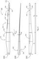
- Fig. 2 shows schematically and exemplarily a rotor blade 200 of a wind turbine, such as in Fig. 1 shown in three views 200A, 200B, 200C.
- the rotor blade 200 has a leading edge 202, a trailing edge 204, a suction side 206, a pressure side 208 and a length Ir.
- the rotor blade 200 is shown from above, i.e. looking at the suction side 206.
- the rotor blade 200 is shown from behind, i.e. looking at the trailing edge 204.
- the rotor blade 200 is shown from below, i.e. looking at the pressure side 208.
- the rotor blade 200 is designed as a two-part rotor blade 200, namely from a first rotor blade component 210 and a second rotor blade component 220, which can be joined together at a separation point 230 to form the actual rotor blade 200.
- a separation point 230 to form the actual rotor blade 200.
- functional or constructive measures are required which extend from the separation point into the rotor blade components 210, 220, in particular into an area B 230 around the separation point.
- the rotor blade 200 is typically divided into individual rotor blade components 210, 220 and transported to the installation site of the wind turbine 100 and assembled on site.
- structural precautions must be taken at the separation point 230, for example thicker layers of material, in order to ensure a reliable connection, for example by bolts or by gluing at the construction site.
- the first rotor blade component 210 and the second rotor blade component 220 are connected to one another in particular lengthwise, i.e. such that the rotor blade 200 has a length I r which is essentially composed of the length I 1 of the first rotor blade component 210 and the length I 2 of the second rotor blade component 220.
- the first rotor blade component 210 comprises a first end 212 for arranging at a blade connection of the wind turbine 100 and a second end 214, which is connected in particular to the first end 222 of the second rotor blade component 220.
- the first rotor blade component 210 can also be referred to as a hub-near rotor blade component.
- the second rotor blade component 220 includes a first end 222, which is connected to the second end 214 of the first rotor blade component 214, and a second end 224, which may also be referred to as a rotor blade tip.
- the second rotor blade component 220 is designed to be significantly longer than the first rotor blade component 210, in particular such that the separation point lies in a range between 15 percent and 40 percent of the length I r of the rotor blade 200.
- the rotor blade optionally has serrations 240 on the trailing edge 206, in particular on the second rotor blade component 220, as well as a Gurney flap 250 on the pressure side 208.
- the Gurney flap 250 particularly preferably extends both over a part of the first rotor blade component 210 and over a part of the second rotor blade component 220 and is therefore arranged in particular in the region of the separation point 230.
- the rotor blade 200 further has an aerodynamically open profile (P), in particular at the separation point 230, as for example in Fig. 3 shown.
- P aerodynamically open profile
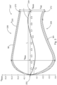
- Fig. 3 shows schematically and exemplarily a profile P 230 of a rotor blade, e.g. as in Fig. 2 shown at a separation point 230 of the rotor blade in a view 230 ⁇ , in particular in cross section.
- Fig. 3 the profile P 230 of the rotor blade 200 can be seen at the separation point 230.
- the profile of the rotor blade 200 is not closed; in this example, the trailing edge has a finite thickness d HK .
- an aerodynamically open profile of the present invention is not limited to this.
- the shape of the trailing edge can also be curved and is not limited to a straight line.
- the direction of the trailing edge can also deviate from a direction perpendicular to the profile depth.
- a sharp transition between the trailing edge and the pressure side 208 or the suction side 206 is not required.
- a continuous or rounded transition can also be provided.
- the thickness of the trailing edge d HK is then determined as the distance between the respective local curvature maxima on the pressure side 208 or the suction side 206, which then define the respective outflow points 270, 272.
- the view 230 ⁇ is supplemented by a Cartesian coordinate system.
- the local profile depth t base is plotted as a percentage on the abscissa of the coordinate system.
- the local profile thickness d base is also plotted as a percentage on the ordinate of the coordinate system, in particular in relation to the profile depth.
- both the second end 214 of the first rotor blade component 210 and the first end 222 of the second rotor blade component 220 have the profile P 230. This enables in particular a positive connection of the two rotor blade components 210, 220 at the separation point 230 of the rotor blade 200.
- the profile P 230 is aerodynamically open, ie the upper side 206 and the lower side 208 of the rotor blade are spaced apart at the trailing edge 204 by a thickness d HK , for example by 1.5 m or as in Fig. 4 shown.
- the P 230 profile has a chord t that runs directly between the leading edge 202 and the trailing edge 204.
- the profile P 230 also has a profile thickness d whose local maximum d max is at approximately 22 percent of the profile depth. This means in particular that the rotor blade has its maximum thickness at approximately 22 percent of the profile depth.
- the distance between the leading edge 202 and the point of maximum thickness d max of the profile P 230 is also referred to as the thickness offset x d .
- the ratio of the thickness offset x d to the profile depth t is also referred to as the relative thickness offset x d '.
- the rotor blade 200 has a material thickening M+ at the separation point 230 or in the area B 230 of the separation point 230, which can also be referred to as preform thickening.
- the material thickening M+ is preferably more than 0.2m and less than 1.0m, preferably between 0.3m and 0.7m, in particular approximately 0.5m.
- the material thickening M+ is to be understood here as an overall structural thickening, which can extend both outwards to increase the profile, i.e. as a contour thickening, but also inwards the profile.
- the rotor blade 200 also has only a slight curvature at the separation point 230 or in the area B 230 of the separation point 230.
- the slight curvature is illustrated by the flat skeleton line s.
- the rotor blade 200 has a so-called back swing at the separation point 230 or in the area B 230 of the separation point 230, i.e. a negative curvature, which is illustrated by the negative course of the skeleton line.
- the skeleton line s therefore has at least one change of sign, in particular in a range between 40 percent and 70 percent of the length I r of the rotor blade.
- Fig. 4 shows schematically and exemplarily a profile of the thickness d HK of the trailing edge 204 over the length I r of the rotor blade 200.
- the trailing edge 204 of the rotor blade is pulled up to the area B 230 of the separation point, e.g. up to 1.5m, and reaches its maximum there, e.g. exactly at the separation point.
- the trailing edge then tapers to 0m, e.g. at a blade length of 45m.
- the profile P of the rotor blade is open up to a blade length of 45 m and is then closed up to the blade tip at 100 m.
- the profile P of the rotor blade 200 is therefore only open in sections and in particular at the separation point 230.
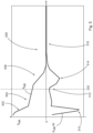
- Fig. 5 shows schematically and exemplarily an alternative course of the thickness d HK of the trailing edge 204 over the length I r of the rotor blade 200 as well as the associated derivative d HK /d r
- the thickness d HK is monotonically decreasing, the maximum is therefore already at or in the vicinity of the blade connection.
- the solution according to the invention can now be seen particularly well in the lower or negative part of the Fig. 5 , in which the derivative d HK /d r is shown.
- the derivative or change in the thickness of the trailing edge d HK /d r is negative over the entire length of the rotor blade, which means that the thickness of the trailing edge is monotonically decreasing.
- the separation point 230 is implemented in the region 512 in which the change in the thickness of the trailing edge d HK /d r has a local maximum. In comparison with this, the thickness of the trailing edge decreases more in the two surrounding regions 510 and 514, which means that the change in the thickness of the trailing edge d HK /d r in the regions 510 and 514 is greater in magnitude. Since the thickness of the trailing edge in the region 508 is zero, the change in the thickness of the trailing edge d HK /d r in the corresponding region 516 is also zero.
Landscapes
- Engineering & Computer Science (AREA)
- Life Sciences & Earth Sciences (AREA)
- Sustainable Development (AREA)
- Sustainable Energy (AREA)
- Chemical & Material Sciences (AREA)
- Combustion & Propulsion (AREA)
- Mechanical Engineering (AREA)
- General Engineering & Computer Science (AREA)
- Physics & Mathematics (AREA)
- Fluid Mechanics (AREA)
- Wind Motors (AREA)
Applications Claiming Priority (2)
| Application Number | Priority Date | Filing Date | Title |
|---|---|---|---|
| DE102022104017.8A DE102022104017A1 (de) | 2022-02-21 | 2022-02-21 | Rotorblatt einer Windenergieanlage |
| EP23153456.1A EP4230862B1 (fr) | 2022-02-21 | 2023-01-26 | Pale de rotor d'une éolienne |
Related Parent Applications (1)
| Application Number | Title | Priority Date | Filing Date |
|---|---|---|---|
| EP23153456.1A Division EP4230862B1 (fr) | 2022-02-21 | 2023-01-26 | Pale de rotor d'une éolienne |
Publications (2)
| Publication Number | Publication Date |
|---|---|
| EP4464889A2 true EP4464889A2 (fr) | 2024-11-20 |
| EP4464889A3 EP4464889A3 (fr) | 2025-01-22 |
Family
ID=85122210
Family Applications (2)
| Application Number | Title | Priority Date | Filing Date |
|---|---|---|---|
| EP24198302.2A Pending EP4464889A3 (fr) | 2022-02-21 | 2023-01-26 | Pale de rotor d'une éolienne |
| EP23153456.1A Active EP4230862B1 (fr) | 2022-02-21 | 2023-01-26 | Pale de rotor d'une éolienne |
Family Applications After (1)
| Application Number | Title | Priority Date | Filing Date |
|---|---|---|---|
| EP23153456.1A Active EP4230862B1 (fr) | 2022-02-21 | 2023-01-26 | Pale de rotor d'une éolienne |
Country Status (4)
| Country | Link |
|---|---|
| US (1) | US20230265826A1 (fr) |
| EP (2) | EP4464889A3 (fr) |
| CN (1) | CN116624322A (fr) |
| DE (1) | DE102022104017A1 (fr) |
Families Citing this family (1)
| Publication number | Priority date | Publication date | Assignee | Title |
|---|---|---|---|---|
| US20250319965A1 (en) * | 2024-04-15 | 2025-10-16 | Lockheed Martin Corporation | Low drag airfoil |
Family Cites Families (25)
| Publication number | Priority date | Publication date | Assignee | Title |
|---|---|---|---|---|
| DE2921152C2 (de) | 1979-05-25 | 1982-04-22 | Messerschmitt-Bölkow-Blohm GmbH, 8000 München | Rotorblatt für Windkraftwerke |
| DE10319246A1 (de) | 2003-04-28 | 2004-12-16 | Aloys Wobben | Rotorblatt einer Windenergieanlage |
| US7883324B2 (en) | 2007-01-09 | 2011-02-08 | General Electric Company | Wind turbine airfoil family |
| EP2031242A1 (fr) | 2007-08-29 | 2009-03-04 | Lm Glasfiber A/S | Élément de pale pour le montage sur une pale d'éolienne et procédé pour modifier le profil aérodynamique d'une pale d'éolienne |
| US8231351B2 (en) | 2007-12-27 | 2012-07-31 | General Electric Company | Adaptive rotor blade for a wind turbine |
| DE102008026474A1 (de) | 2008-06-03 | 2009-12-10 | Mickeler, Siegfried, Prof. Dr.-Ing. | Rotorblatt für eine Windkraftanlage sowie Windkraftanlage |
| DE102008052858B9 (de) | 2008-10-23 | 2014-06-12 | Senvion Se | Profil eines Rotorblatts und Rotorblatt einer Windenergieanlage |
| US8092187B2 (en) | 2008-12-30 | 2012-01-10 | General Electric Company | Flatback insert for turbine blades |
| EP2253838A1 (fr) * | 2009-05-18 | 2010-11-24 | Lm Glasfiber A/S | Procédé de fonctionnement d'une éolienne |
| DE102009023001A1 (de) | 2009-05-28 | 2010-12-02 | Smart Blade Gmbh | Modulares Rotorblatt für eine Windkraftanlage |
| DK178073B1 (en) * | 2011-06-17 | 2015-04-27 | Envision Energy Denmark Aps | A Wind Turbine Blade |
| EP2795105B1 (fr) | 2011-12-22 | 2021-02-17 | LM WP Patent Holding A/S | Pale d'éolienne assemblée depuis la partie interne et partie externe dotée de différents types de structures de support de charge |
| DE102012206109C5 (de) | 2012-04-13 | 2022-06-09 | Wobben Properties Gmbh | Rotorblatt einer Windenergieanlage |
| EP2713044B2 (fr) | 2012-09-28 | 2022-12-07 | Siemens Gamesa Renewable Energy A/S | Pale de rotor d'éolienne |
| DE102013202666A1 (de) | 2013-02-19 | 2014-08-21 | Senvion Se | Rotorblatt einer Windenergieanlage |
| DE102017124861A1 (de) | 2017-10-24 | 2019-04-25 | Wobben Properties Gmbh | Rotorblatt einer Windenergieanlage und Verfahren zu dessen Auslegung |
| DE102018103732A1 (de) | 2018-02-20 | 2019-08-22 | Wobben Properties Gmbh | Rotorblatt für eine Windenergieanlage und Verfahren |
| DE102018112833A1 (de) | 2018-05-29 | 2019-12-05 | Wobben Properties Gmbh | Windenergieanlagen-Rotorblatt |
| DE102018121190A1 (de) | 2018-08-30 | 2020-03-05 | Wobben Properties Gmbh | Rotorblatt, Windenergieanlage und Verfahren zum Optimieren einer Windenergieanlage |
| DE102018127367A1 (de) | 2018-11-02 | 2020-05-07 | Wobben Properties Gmbh | Rotorblatt für eine Windenergieanlage und Windenergieanlage |
| DE102019113085A1 (de) | 2019-05-17 | 2020-11-19 | Wobben Properties Gmbh | Rotorblatt und Windenergieanlage |
| DE102019113080A1 (de) | 2019-05-17 | 2020-11-19 | Wobben Properties Gmbh | Rotorblatt und Windenergieanlage |
| DE102019119027B4 (de) | 2019-07-12 | 2022-04-28 | Wobben Properties Gmbh | Rotorblatt und Windenergieanlage |
| PL3855014T3 (pl) | 2020-01-22 | 2025-10-20 | Nordex Energy Se & Co. Kg | Dzielona łopata wirnika turbiny wiatrowej oraz segment łopaty wirnika |
| GB202006893D0 (en) | 2020-05-11 | 2020-06-24 | Lm Wind Power As | Blade shell section and a wind turbine blade comprising a blade shell section |
-
2022
- 2022-02-21 DE DE102022104017.8A patent/DE102022104017A1/de not_active Withdrawn
-
2023
- 2023-01-26 EP EP24198302.2A patent/EP4464889A3/fr active Pending
- 2023-01-26 EP EP23153456.1A patent/EP4230862B1/fr active Active
- 2023-02-10 US US18/167,636 patent/US20230265826A1/en not_active Abandoned
- 2023-02-17 CN CN202310134563.9A patent/CN116624322A/zh not_active Withdrawn
Also Published As
| Publication number | Publication date |
|---|---|
| EP4230862B1 (fr) | 2024-09-04 |
| EP4464889A3 (fr) | 2025-01-22 |
| CN116624322A (zh) | 2023-08-22 |
| EP4230862C0 (fr) | 2024-09-04 |
| US20230265826A1 (en) | 2023-08-24 |
| EP4230862A1 (fr) | 2023-08-23 |
| DE102022104017A1 (de) | 2023-08-24 |
Similar Documents
| Publication | Publication Date | Title |
|---|---|---|
| EP1514023B1 (fr) | Eolienne | |
| EP2998572B1 (fr) | Pale de rotor d'éoliennes | |
| EP2363599B2 (fr) | Pale de rotor pour une éolienne, éolienne et procédé de fabrication d'une pale de rotor | |
| EP2788618B1 (fr) | Caisson arrière, pale de rotor avec caisson arrière et éolienne équipée d'une pale de rotor | |
| EP2836702B1 (fr) | Pale d'éolienne | |
| EP3855014B1 (fr) | Pale de rotor divisée d'une éolienne ainsi que segment de pale de rotor | |
| EP2280163B1 (fr) | Eolienne et pale de rotor d'une eolienne | |
| EP4108909B1 (fr) | Pale de rotor d'une éolienne et son procédé de conception | |
| EP3559417B1 (fr) | Procédé de fabrication d'une pale de rotor d'éolienne et pale de rotor d'éolienne | |
| DE202013007886U1 (de) | Windenergieanlagenrotorblatt mit passiver Lastreduzierung | |
| EP2366892B1 (fr) | Pale de rotor d'éolienne | |
| EP2568166B1 (fr) | Pale de rotor d'éolienne dotée d'un rebord arrière à profil épais | |
| EP4230862B1 (fr) | Pale de rotor d'une éolienne | |
| EP3399183B1 (fr) | Pale de rotor d'une éolienne | |
| EP3356669B1 (fr) | Pale de rotor d'éolienne et éolienne | |
| EP2363602A2 (fr) | Pale pour une installation de production d'énergie par écoulement | |
| EP3969743B1 (fr) | Pale de rotor et méthode de conception d'une pale de rotor d'une eolienne. | |
| EP2679803A1 (fr) | Pale de rotor d'éolienne dotée d'un bord de fuite à profil épais | |
| EP3844384B1 (fr) | Rotor comprenant une pale de rotor, éolienne et procédé d'optimisation d'une éolienne | |
| WO2016162350A1 (fr) | Pale de rotor d'éolienne | |
| EP3553306B1 (fr) | Pale de rotor d'une éolienne pourvue d'un générateur de vortex | |
| DE102016014908A1 (de) | Rotorblatt, Windenergieanlage mit einem Rotorblatt und Reparatursatz und Verfahren zum Verstärken eines Rotorblatts |
Legal Events
| Date | Code | Title | Description |
|---|---|---|---|
| PUAI | Public reference made under article 153(3) epc to a published international application that has entered the european phase |
Free format text: ORIGINAL CODE: 0009012 |
|
| STAA | Information on the status of an ep patent application or granted ep patent |
Free format text: STATUS: THE APPLICATION HAS BEEN PUBLISHED |
|
| AC | Divisional application: reference to earlier application |
Ref document number: 4230862 Country of ref document: EP Kind code of ref document: P |
|
| AK | Designated contracting states |
Kind code of ref document: A2 Designated state(s): AL AT BE BG CH CY CZ DE DK EE ES FI FR GB GR HR HU IE IS IT LI LT LU LV MC ME MK MT NL NO PL PT RO RS SE SI SK SM TR |
|
| PUAL | Search report despatched |
Free format text: ORIGINAL CODE: 0009013 |
|
| AK | Designated contracting states |
Kind code of ref document: A3 Designated state(s): AL AT BE BG CH CY CZ DE DK EE ES FI FR GB GR HR HU IE IS IT LI LT LU LV MC ME MK MT NL NO PL PT RO RS SE SI SK SM TR |
|
| RIC1 | Information provided on ipc code assigned before grant |
Ipc: F03D 1/06 20060101AFI20241216BHEP |
|
| STAA | Information on the status of an ep patent application or granted ep patent |
Free format text: STATUS: REQUEST FOR EXAMINATION WAS MADE |
|
| 17P | Request for examination filed |
Effective date: 20250722 |
|
| STAA | Information on the status of an ep patent application or granted ep patent |
Free format text: STATUS: EXAMINATION IS IN PROGRESS |
|
| 17Q | First examination report despatched |
Effective date: 20250903 |