EP4464945A1 - Système de régulation de température d'un bâtiment - Google Patents
Système de régulation de température d'un bâtiment Download PDFInfo
- Publication number
- EP4464945A1 EP4464945A1 EP24176805.0A EP24176805A EP4464945A1 EP 4464945 A1 EP4464945 A1 EP 4464945A1 EP 24176805 A EP24176805 A EP 24176805A EP 4464945 A1 EP4464945 A1 EP 4464945A1
- Authority
- EP
- European Patent Office
- Prior art keywords
- heat
- building
- mass storage
- line
- room
- Prior art date
- Legal status (The legal status is an assumption and is not a legal conclusion. Google has not performed a legal analysis and makes no representation as to the accuracy of the status listed.)
- Withdrawn
Links
Images



Classifications
-
- F—MECHANICAL ENGINEERING; LIGHTING; HEATING; WEAPONS; BLASTING
- F24—HEATING; RANGES; VENTILATING
- F24F—AIR-CONDITIONING; AIR-HUMIDIFICATION; VENTILATION; USE OF AIR CURRENTS FOR SCREENING
- F24F5/00—Air-conditioning systems or apparatus not covered by F24F1/00 or F24F3/00, e.g. using solar heat or combined with household units such as an oven or water heater
- F24F5/0007—Air-conditioning systems or apparatus not covered by F24F1/00 or F24F3/00, e.g. using solar heat or combined with household units such as an oven or water heater cooling apparatus specially adapted for use in air-conditioning
- F24F5/0017—Air-conditioning systems or apparatus not covered by F24F1/00 or F24F3/00, e.g. using solar heat or combined with household units such as an oven or water heater cooling apparatus specially adapted for use in air-conditioning using cold storage bodies, e.g. ice
-
- F—MECHANICAL ENGINEERING; LIGHTING; HEATING; WEAPONS; BLASTING
- F24—HEATING; RANGES; VENTILATING
- F24D—DOMESTIC- OR SPACE-HEATING SYSTEMS, e.g. CENTRAL HEATING SYSTEMS; DOMESTIC HOT-WATER SUPPLY SYSTEMS; ELEMENTS OR COMPONENTS THEREFOR
- F24D11/00—Central heating systems using heat accumulated in storage masses
- F24D11/002—Central heating systems using heat accumulated in storage masses water heating system
- F24D11/003—Central heating systems using heat accumulated in storage masses water heating system combined with solar energy
-
- F—MECHANICAL ENGINEERING; LIGHTING; HEATING; WEAPONS; BLASTING
- F24—HEATING; RANGES; VENTILATING
- F24D—DOMESTIC- OR SPACE-HEATING SYSTEMS, e.g. CENTRAL HEATING SYSTEMS; DOMESTIC HOT-WATER SUPPLY SYSTEMS; ELEMENTS OR COMPONENTS THEREFOR
- F24D11/00—Central heating systems using heat accumulated in storage masses
- F24D11/02—Central heating systems using heat accumulated in storage masses using heat pumps
- F24D11/0214—Central heating systems using heat accumulated in storage masses using heat pumps water heating system
- F24D11/0221—Central heating systems using heat accumulated in storage masses using heat pumps water heating system combined with solar energy
-
- F—MECHANICAL ENGINEERING; LIGHTING; HEATING; WEAPONS; BLASTING
- F24—HEATING; RANGES; VENTILATING
- F24D—DOMESTIC- OR SPACE-HEATING SYSTEMS, e.g. CENTRAL HEATING SYSTEMS; DOMESTIC HOT-WATER SUPPLY SYSTEMS; ELEMENTS OR COMPONENTS THEREFOR
- F24D2200/00—Heat sources or energy sources
- F24D2200/12—Heat pump
-
- F—MECHANICAL ENGINEERING; LIGHTING; HEATING; WEAPONS; BLASTING
- F24—HEATING; RANGES; VENTILATING
- F24D—DOMESTIC- OR SPACE-HEATING SYSTEMS, e.g. CENTRAL HEATING SYSTEMS; DOMESTIC HOT-WATER SUPPLY SYSTEMS; ELEMENTS OR COMPONENTS THEREFOR
- F24D2200/00—Heat sources or energy sources
- F24D2200/14—Solar energy
-
- F—MECHANICAL ENGINEERING; LIGHTING; HEATING; WEAPONS; BLASTING
- F24—HEATING; RANGES; VENTILATING
- F24D—DOMESTIC- OR SPACE-HEATING SYSTEMS, e.g. CENTRAL HEATING SYSTEMS; DOMESTIC HOT-WATER SUPPLY SYSTEMS; ELEMENTS OR COMPONENTS THEREFOR
- F24D2220/00—Components of central heating installations excluding heat sources
- F24D2220/006—Parts of a building integrally forming part of heating systems, e.g. a wall as a heat storing mass
-
- F—MECHANICAL ENGINEERING; LIGHTING; HEATING; WEAPONS; BLASTING
- F24—HEATING; RANGES; VENTILATING
- F24F—AIR-CONDITIONING; AIR-HUMIDIFICATION; VENTILATION; USE OF AIR CURRENTS FOR SCREENING
- F24F5/00—Air-conditioning systems or apparatus not covered by F24F1/00 or F24F3/00, e.g. using solar heat or combined with household units such as an oven or water heater
- F24F5/0046—Air-conditioning systems or apparatus not covered by F24F1/00 or F24F3/00, e.g. using solar heat or combined with household units such as an oven or water heater using natural energy, e.g. solar energy, energy from the ground
- F24F2005/0064—Air-conditioning systems or apparatus not covered by F24F1/00 or F24F3/00, e.g. using solar heat or combined with household units such as an oven or water heater using natural energy, e.g. solar energy, energy from the ground using solar energy
-
- F—MECHANICAL ENGINEERING; LIGHTING; HEATING; WEAPONS; BLASTING
- F24—HEATING; RANGES; VENTILATING
- F24F—AIR-CONDITIONING; AIR-HUMIDIFICATION; VENTILATION; USE OF AIR CURRENTS FOR SCREENING
- F24F5/00—Air-conditioning systems or apparatus not covered by F24F1/00 or F24F3/00, e.g. using solar heat or combined with household units such as an oven or water heater
- F24F5/0046—Air-conditioning systems or apparatus not covered by F24F1/00 or F24F3/00, e.g. using solar heat or combined with household units such as an oven or water heater using natural energy, e.g. solar energy, energy from the ground
- F24F2005/0064—Air-conditioning systems or apparatus not covered by F24F1/00 or F24F3/00, e.g. using solar heat or combined with household units such as an oven or water heater using natural energy, e.g. solar energy, energy from the ground using solar energy
- F24F2005/0067—Air-conditioning systems or apparatus not covered by F24F1/00 or F24F3/00, e.g. using solar heat or combined with household units such as an oven or water heater using natural energy, e.g. solar energy, energy from the ground using solar energy with photovoltaic panels
Definitions
- the present invention has set itself the task of proposing a system for temperature control of at least one room of a building, which at least at comparable costs leads to a higher self-sufficiency in temperature control and thus to a reduction in the consumption of fossil fuels.
- the fluid heated by the solar collector serves as a heat source for the thermal cooling machine.
- the removal of excess heat from solar thermal energy serves to protect the system and in turn increases the service life of the modules and increases the system's utilization rate by 40%.
- the surface temperature control element is designed as a wall surface temperature control element, in particular of an interior wall in the building, as a ceiling surface temperature control element, in particular as an air-conditioned ceiling or as underfloor heating.
- An air-conditioned ceiling has the functionality of a cooling and heating ceiling.
- the flow temperature of the surface temperature control element is a maximum of 35°C, preferably a maximum of 30°C. It has been found that this temperature level is completely sufficient to achieve adequate temperature control in the room.
- the flow temperatures can often even be reduced to below 30°C (e.g. to 22°C, 24°C, 25°C, 27°C or 28°C), and on walls, roofs or floors that have a direct outflow of room heat to the environment, often even below 20°C.
- the building mass storage is operated in a temperature range of 16 °C and 45 °C.
- the temperature interval of 16 °C still avoids condensation problems on the cold surfaces, but at the same time a significant cooling potential is made available at this temperature, which contributes to a pleasant room temperature on hot days.
- the upper limit of the temperature interval is 45 °C. With such an upper limit, it is also possible to renovate relatively poorly insulated buildings with high heat requirements in terms of energy and to control the temperature in a way that avoids CO2 in winter.
- a maximum temperature of 45°C is provided for in old buildings with floating screed and 35°C for old buildings with bonded screed. This prevents unpleasant overheating of the floor, which would otherwise only be possible with additional insulation.
- the "actively usable" heat reserve is formed from the temperature difference between the flow temperature of the surface temperature control element ("quick ceiling") and the building mass storage. In a dark winter period, which is not very cold and the heating demand does not reach its maximum, a flow temperature of 25°C is sufficient.
- the building mass becomes an “active storage” compared to the quick, under-mounted ceiling heating at any temperature equal to or greater than 25°C.
- the storage also works “passively” with the function of "temperature control of thermal bridges" and "introduction of transmission heat flows into the room” at any storage temperature that is higher than the room air temperature, or in the case of the thermal bridge that is higher than the outside temperature.
- the temperature level of the building mass storage from 25 °C to 30, 35, 40 or 45 °C also serves as control heating (in addition to heating the thermal bridges, providing base load heating) by taking heat from the building mass storage and feeding it to the large-scale, but with surface temperature control element with low heat storage capacity.
- the system is therefore characterized by the fact that the heat reserve of the building mass storage with a temperature level between 16 °C and 20 °C is used to heat thermal bridges in the building, the heat reserve of the building mass storage with a temperature level between 20 °C and 25 °C is used, on the one hand, to heat thermal bridges in the building and, on the other hand, to form the base load heating to temperature the room, and the heat reserve of the building mass storage with a temperature level between 25 °C and 45 °C is used, on the one hand, to heat thermal bridges in the building, to form the base load heating to temperature the room, and to supply the surface temperature control element with heat as a control heater to temperature the room.
- the specified temperature limits are variable within limits of 2 to 3 K, depending on the operating location of the system according to the invention.
- the invention is characterized in that the temperature difference between the building mass storage and the surface temperature control element is between 2 and 30K.
- the building mass storage device designed as a building floor ceiling, at a maximum storage temperature of the building mass storage device of 35 °C, maintains a heat reserve for the at least one room covered by the building floor ceiling, which is sufficient to temper the at least one room covered by the building floor ceiling to an average of at least 18 °C, preferably at least 20 °C, for at least two, at least four, at least six or at least eight days.
- the aim here is in particular to temper an apartment that consists of a plurality of rooms in the sense of the above-described feature and is part of an apartment building with several apartments, cost-effectively and without CO2 emissions.
- the at least one room includes living rooms (bedroom, work room, living room, bathroom, hallway), but not necessarily hallways or other general areas in front of the apartment door, which are often tempered at a lower temperature level (if they are thermally separated, for example). It has been found that this heat balance can be achieved with the proposal according to the invention, namely with a system temperature starting from 20 °C, up to preferably 30 °C, 35 °C or 45 °C, no or only minimal thermal insulation of the building mass storage and the use of the exergetic solar heat obtained by the solar collector or other regeneratively obtained heat.
- thermal insulation is only provided on the underside of the lowest floor of the building and on the top of the top ceiling of the building to limit thermal (storage) losses to the environment, and the external walls have no thermal insulation. It was found that this minimally invasive insulation is sufficient in the inventive concept, as the heat losses from thermal interference surfaces and thermal bridges can be compensated for at low temperatures using solar thermal energy or other renewable energy. Facade insulation is deliberately omitted and the associated financial expenditure is saved.
- the concept includes measures to ensure that the building is airtight, which means that the building itself is airtight so that no heat energy is accidentally lost through uncontrolled currents. This measure significantly reduces the use of resources for insulation material, as insulation measures are only taken on the basement ceiling and the top floor ceiling, which already has a relevant effect in reducing demand.
- the lowest floor is, for example, the floor of the ground floor (or the basement ceiling), which can be easily insulated later, particularly in the case of renovation.
- the floor slab which is founded on the ground, can also be the lowest floor; both variants are part of the invention.
- the concept of minimally invasive insulation also means that the building mass storage (for example the ceilings) are not or only minimally insulated. The resulting storage losses are not lost, however! These become base load heating (even at low storage temperatures) and/or reduce the room-related transmission losses against the outside temperature and, in addition to the heating water system temperature, also reduce the effort of actively transporting heat from the storage (building mass) to the surface temperature control element.
- a heat pump is provided which is connected to the building mass storage system by a fourth line and in which a fluid that can be heated or cooled circulates to transport heat or cold.
- the heat pump is preferably operated with electricity produced from renewable sources, for example from the photovoltaic system integrated in the system.
- the adsorption module is responsible for converting heat into cold and is therefore the heart of solar cooling.
- the removal of excess heat in solar thermal systems is considered to be system protection and in turn increases the module service life and increases the system's utilization rate by 40%.
- the recooler of the adsorption or absorption chiller serves as an air collector for the heat pump in the heating case.
- the excess energy is transferred to the adsorption/absorption process via a coolant circuit directly or indirectly via a closed Brine or water circuit. Due to the higher specific heat capacity of the cooling circuit of the water or brine heat pump and the closed routing of the medium, the weight and (energy and system-related) effort for transporting the medium can be reduced to a minimum.
- This system constellation represents an optimization between system functions, their utilization rates and their service life.
- the proposal advantageously provides for the heat pump to be designed as a water-water heat pump or as a brine-water heat pump. These types of heat pumps are characterized by higher annual performance factors, meaning they work more energy efficiently. A brine-water heat pump also allows it to be operated at temperatures below 0°.
- the invention astonishingly presents a cost-effective alternative for the energy renovation of existing properties, which leads to a high level of self-sufficiency and a considerable reduction in CO2 while at the same time significantly reducing the load on the electricity grids of the buildings renovated in this way! It has been found that the renovation of the residential units with the system according to the invention is possible while they are still occupied. This increases the acceptance of this measure and avoids moving costs.
- the system according to the invention uses this combination of system components to activate the full potential of decentrally available resources, using otherwise "lost" heat from low temperature zones, for example through low-temperature solar thermal energy, and activating previously neglected structural reserves, such as building mass, the concrete ceilings as heat storage and supply medium against thermal bridge losses.
- the invention minimizes thermal requirements and losses through a systemic low-temperature regime and fulfills and integrates the system-critical heat functions in an energy cycle architecture in which various components are coupled with low losses and operated in their optimal states by control algorithms.
- the advantage of the invention is that existing heat (e.g. obtained from renewable energy sources / solar collectors) is stored in existing building mass storage with a large heat storage capacity.
- the invention is well aware that this interaction can be used to provide sufficient room temperature without producing CO2.
- thermal insulation 8.81 is arranged on the ceiling 21z.
- a thermal insulation 8.80 is also provided under the lowest floor 20z.
- the thermal insulation 80 is in Figure 1 as thermal insulation arranged under a floor slab, but without restricting the invention to this.
- the floor of the ground floor is also considered to be the lowest floor 20z according to the invention, with the thermal insulation then being arranged on the basement ceiling below. This embodiment is also covered by the invention.
- the system according to the invention comprises a heat pump 9.
- the heat pump 9, in Fig. 2 also marked as “WP”, is connected to the heat or cold storage tank 40 via line 54.
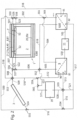
- the building is identified by reference number 1.
- the ceiling element 21a acts, as described, as a building mass storage device 4, or as a heat or cold storage device 40.
- the heated fluid flow leaves the solar collector 3 in line 509.
- Line 509 is connected to the building mass storage device 4 via valve 553, line 508, valve 556 and line 507.
- Fluid heated by the sun i.e. heat
- the return flow from the building mass storage device 4 to the inlet of the solar collector 3 takes place via line 501, valve 550, line 500, valve 555 and line 524.
- the inlet and return flow described above describe the first line 51.
- the room 2 is heated by the storage losses of the building mass storage 4, which thus forms a basic heating system, and the surface temperature control element 7, which is arranged below the ceiling 21 and emits radiant heat into the room 2.
- the inflow from the building mass storage 4 into the surface temperature control element 7 takes place via the line 507, the valve 556, the line 525, the valve 557 and the line 522.
- the return takes place via the line 523, the valve 558, the line 526, the valve 550 and the line 501. It is clear that the flow direction of the fluid can also be reversed, ie the inflow is the return and the return is the inflow.
- the previously described inflow and return describe the second line 52, which in Figure 2 is also indicated in abbreviated form.
- the system according to the invention not only provides heat, but also cold with the help of the refrigeration machine 6, which is preferably designed as an adsorption refrigeration machine 60.
- the supply of heat from the building mass storage 4 into the refrigeration machine 6 takes place via the line 501, the valve 550, the line 526, the valve 558, the line 502, the valve 551 and the line 503.
- the return from the refrigeration machine 6 takes place via the line 519, the valve 552, the line 506, the valve 557, the line 525, the valve 556 and the line 507.
- the previously described supply and return describe the third line 53.
- the system according to the invention also includes a heat pump 9, with which additional heat can be generated if necessary.
- the heat produced by the heat pump 9 is then also fed into the building mass storage 4.
- the supply to the building mass storage 4 from the heat pump 9 takes place via line 505, valve 552, line 506, valve 557, line 525, valve 556 and line 507.
- the return takes place via line 501, valve 550, line 526, valve 558, line 502, valve 551 and line 504.
- the previously described supply and return describe the fourth line 54.
- a photovoltaic system 11 is installed on the roof 12, in Fig. 2 also designated as "PV".
- the electricity produced by this photovoltaic system 11 supplies the electrical components of the system, in particular the heat pump 9 via the power line 530 and the refrigeration machine 6 via the power line 531.
- the solar collector 3 not only supplies the building mass storage 4 with the heat energy it collects. It is also possible for its fluid flow to be directed completely or partially directly to the surface temperature control element 7.
- the inflow takes place via line 509 (connected to the solar collector 3 on the output side), valve 553, line 508, valve 556, line 525, valve 557 and line 522.
- the return takes place via line 523, valve 558, line 536, valve 550, line 500, valve 555 and line 524 into the inlet of the solar collector 3.
- the solar collector 3 also serves as a heat source for the heat pump 9.
- the heat generated by the heat pump 9 is conveyed to the building mass storage tank 4 via the fourth line 54.
- the connection of the solar collector 3 as a heat supplier for the heat pump 9 is made via the line 509, the valve 553, the line 510, the valve 559 and the line 512 to the heat inlet 90 of the heat pump 9.
- the return flow takes place from the cold outlet 91 of the heat pump 9 via the line 513, the valve 559, the line 514, the valve 554, the line 516, the valve 555 and the line 524 to the inlet of the solar collector 3.
- the system according to the invention also includes the possibility of using the solar collector 3 as a heat source for the thermal cooling machine 6.
- the cooling machine 6 is connected to the building mass storage 4 via the third line 53 described and cools it down.
- the cooling machine 6 also partially or completely cools the surface temperature control element 7 and thus contributes to cooling the room 2.
- the thermal cooling machine 6 has a heat inlet 61.
- the output line 509 of the solar collector 3 is connected to the heat inlet 61 via the valve 553 and the line 518.
- the cold outlet 62 of the cooling machine 6 is connected to the solar collector 3's own line 524 via the line 517, the valve 554, the line 516, the valve 555, thus closing this circuit.
- the system according to the invention is open and can include additional heat sources 39 in addition to the solar collector 3.
- the heat source 39 is, for example, a geothermal heat source that is accessed via a deep borehole or a probe, process waste heat or district heating, etc.
- the heat from this heat source 39 is used, for example, to heat the building mass storage unit 4 and/or the surface temperature control element 7. or to temper it. This is done via the output line 511 of the heat source 39, the valve 560, the line 527, the valve 552, the line 506 into the valve 557. From there, the surface tempering element 7 can then be operated via the line 552 and/or the building mass storage 4 can be operated via the line 525, the valve 556 and the line 507.
- the return from the surface temperature control element 7 takes place via line 523 into the valve 558, line 526, the valve 550, line 500, the valve 555, line 516, the valve 554, line 515, the valve 559 into the inlet line 528 of the other heat source 39.
- the return from the building mass storage 4 takes place via line 501 into the valve 550, line 500, the valve 555, line 516, the valve 554, line 515, the valve 559 into the inlet line 528 of the other heat source 39.
- the heat collected by solar collector 3 serves as input heat in the thermal cooling machine 6.
- the output line 509 of the solar collector 3 is connected to the heat input 61 of the cooling machine 6 via the valve 553, the line 518.
- the cold output 62 is connected to the input line 524 of the solar collector 3 via the line 517, the valve 554, the line 516, the valve 555.
- a line 521 it is possible for a line 521 to branch off from the line 517, in front of the valve 554, which connects the cold output 62 to the input line 528 of the other heat source 39 via the valve 559.
- this is also possible via the valve 554 and the line 515.
- the heat collected by solar collector 3 serves as input heat in the heat pump 9 and thus increases the temperature level and the coefficient of performance.
- the output line 509 of the solar collector 3 is connected to the heat inlet 90 of the heat pump 9 via the valve 553, the line 510, the valve 559, and the line 512.
- the return from the cold outlet 91 of the heat pump 9 takes place via the line 513, the valve 559, the line 515, the valve 554, the line 516, the valve 555 into the input line 524 of the solar collector 3.
- the Figure 3 differs from the one in Figure 2 shown variant in that the individual elements of the heat sources or heat sinks are supplied by hydraulic switches.
- the hydraulic switches are preferably large-volume containers into which a large number of inlets and outlets flow. They serves to hydraulically decouple the various circuits from one another. This ensures that the pumps in the various circuits with their different pressure and volume flow parameters do not influence one another.
- a cold water switch KWW is provided to supply the heat sources with colder water
- a hot water switch WWW is provided to collect and distribute heated water.
- these switches always represent a certain amount of storage that can serve as an intermediate storage facility.
- valve V1 If the temperature level of the fluid heated by the solar collector 3 on the output side is too low for feeding into the building mass storage tank 4 (or into the hot water switch WWW), it is possible to set the valve V1 to a second position, via which the heated fluid then passes the heat exchanger WT1 via a bypass line BP2 directly into the return line 516. In this case, the valve V9 is also in its second position, through which the heat exchanger 9 is bypassed by the line 529. The fluid then passes via the line 529 directly into the solar collector 3 for further heating via the supply line 524. It is clear that the valves V1 and V9 can be controlled accordingly.
- one or more additional heat sources 39 are provided. These are supplied with fluid (water) to be acquired from the cold water switch KWW via line 528 and are connected via line 511 to the hot water switch WWW into which the fluid (water) heated by it is fed.
- the hot water switch WWW and the cold water switch KWW are connected for return purposes via the return line RL1.
- the valve V7 is provided in the pipe section 511, which in its 1st position creates a connection with the hot water switch WWW. In its 2nd position, the fluid does not enter the hot water switch WWW, but rather via the bypass line BP1 directly into the return line RL1 and from there back into the cold water switch KWW. This makes it possible to increase the temperature level.
- the heat pump 9 it is possible to raise the temperature level of the fluid, particularly in the hot water switch WWW, and to use the lower, but still warmer than the environment, temperature level of the fluid in the cold water switch KWW.
- the primary side of the heat pump 9 is fluidically connected to the cold water switch KWW.
- the inflow from the cold water switch KWW is via line 512 into connection W on the primary side, the return via line 513 from connection K into the cold water switch KWW.
- the mode of operation of the heat pump 9 is that heat is extracted from a tempered, preferably liquid heat medium (for example water) on the primary side and is used to efficiently heat a liquid heat medium (also preferably water).
- a tempered, preferably liquid heat medium for example water
- a liquid heat medium also preferably water
- the K connection of the secondary side of the heat pump 9 is fed by the return line 500 (as supply line 520), which is ultimately connected on the output side either to the building mass storage tank 4 and/or the surface temperature control element 7.
- a bypass line from the hot water switch WWW into the return line 501 which can be used, for example, to bridge the building mass storage tank 4 or the surface temperature control element 7.
- the W connection of the secondary side of the heat pump 9 feeds the heated fluid into the hot water switch WWW via line 505.
- the building mass storage tank 4 has the task of storing heat or, in the case of cooling, cold. Depending on the application, the building mass storage tank 4 is therefore heated or cooled by the fluid (water) flowing through it. In order to heat the building mass storage tank 4, it is fluidically connected to the hot water switch WWW via lines 581 and 507. Between the line sections 581 and 507 there is the changeover valve V2, which in a 1st switching position connects the hot water switch WWW to the building mass storage tank 4.
- line 501 is connected to the building mass storage tank 4, which fluidically connects the building mass storage tank 4 to the hot water switch WWW via the changeover valve 558 (in its 1st position), the line section 502, the changeover valve V4, the line 500, the changeover valve V5 in its first position and the return line section 599. In its 2nd position, line 500 opens as supply line 520 into the K connection of the secondary side of heat pump 9.
- the building mass storage unit 4 has several tasks. In addition to storing cold or heat, the building mass storage unit 4 also serves as a base load heating system for room 2, since the building mass storage unit 4 is not, hardly or only minimally insulated from room 2. This means that the unavoidable heat losses from the building mass storage unit 4 are not lost, but rather cover part of the room heating.
- the surface temperature control element 7 is provided for a fast, in particular controllable, standard heating system. For this purpose, as already described, this is connected to the building mass storage unit 4 via the lines 52 and is supplied with heat by this as required.
- the heated fluid from the building mass storage 4 is fed via the line section 501, the switching valve 558 in its 2nd position, and the pipe section 523 into the surface temperature control element 7, where it leaves the end of the pipe section 522 and passes through the switching valve V3 into the return line 586, from where it is pumped back into the building mass storage 4 in a circle via the switching valve V2 and the pipe section 507.
- a pump (not shown) is provided on the outlet side of the building mass storage 4, in the pipe section 501.
- the flow direction of the fluid is clockwise in this case.
- the double arrow indicates that the fluid in the pipe sections 522 or 523 flows in one or the opposite direction.
- the surface temperature control element 7 is supplied directly with warm fluid from the hot water switch WWW.
- the hot water switch WWW is connected to the surface temperature control element 7 via the line 582, the changeover valve V3 and the line section 522.
- the changeover valve V3 has several positions and in its first position fluidically connects the line sections 582 and 522.
- the surface temperature control element 7 is connected to the changeover valve 558 via the line 523.
- the fluid cooled in the heating case is then returned to the hot water switch WWW via the line section 502, the changeover valve V4 and the line 500, the changeover valve V5 in its first position and the return line section 599.
- the system also includes the use of a refrigeration machine 6, in particular an adsorption refrigeration machine 60.
- a refrigeration machine 6 in particular an adsorption refrigeration machine 60.
- the advantage of this proposal is that cold can be generated from solar heat or heat from other renewable energy sources using an adsorption refrigeration machine 60.
- the flow line W of the primary side of the adsorption chiller 60 is fluidically connected to the hot water switch WWW via line 583.
- the fluid cooled in the primary side of the absorption chiller 60 is fed into the hot water switch WWW via line 584 connected to connection K.
- the building mass storage tank 4 and/or the surface temperature control element 7 are not supplied from the hot water switch WWW, but from line 585 connected to the K connection on the secondary side of the absorption chiller 60.
- the line 585 flows directly into the building mass storage tank 4 and the connection from the hot water switch WWW to the building mass storage tank 4 is separated by a shut-off valve.
- the line 585 ends in the switching valve V2.
- the line 585 is fluidically connected to the supply line 507 of the building mass storage device 4. Cooled fluid then reaches the building mass storage device 4 via this path and cools it down.
- the building mass storage device 4 then serves as a cold storage device. Cold is then extracted from this cold storage device via the lines 52, in which the fluid circulating here is cooled in the cold building mass storage device 4 and thus cools the surface temperature control element 7, which in turn can absorb heat from the room 2 and extract it.
- the line 585 connects the connection K of the secondary side of the adsorption chiller 60 with the changeover valve V3. It is provided that the changeover valve V3 can assume several positions.
- the outlet line 582 of the hot water switch WWW is connected to the supply line 522 in the surface temperature control element 7 and thus the surface temperature control element 7 is warmed or heated up.
- the line 585 from the adsorption chiller 60 is connected to the supply line 522 of the surface temperature control element 7.
- cold fluid from the adsorption chiller 60 passes directly into the surface temperature control element 7 and cools it and thus also the room 2.
- the line 585 is fluidically connected to the connecting line 586.
- the connecting line 586 connects the two switching valves V2 and V3.
- the switching valve V2 is preferably switched in its second position so that the connecting line 586 is connected to the supply line 507 of the building mass storage 4.
- the building mass storage 4 serves as a cooling storage and is cooled by the cold fluid.
- the return of the fluid from the building mass storage 4 or the surface temperature control element 7 takes place in the cooling case via the same lines 501 and 502, or 523 and 502 as in the heating case.
- the changeover valve V4, into which the line 502 flows, is preferably in the second position in the cooling case.
- the return line 502 is connected to the supply line 587, which connects the changeover valve V4 to the W connection of the secondary side of the adsorption chiller 60 and thus makes fluid to be cooled available to the adsorption chiller 60.
- the waste heat generated during the production of cold in the adsorption chiller 6.60 is fed into the cold water switch KWW via the outlet 540.
- the return line for this is designated 541.
- Both the cold water switch KWW and the hot water switch WWW are preferably designed as buffer storage, in particular as a layered buffer storage. This allows the fluid to be supplied or removed at the correct temperature level, while avoiding the generation of entropy.
- the hot water switch WWW represents an expansion of the capacity of the heat storage volume of the building mass storage 4.
- circuit diagrams shown here do not include pumps, which are nevertheless provided at the necessary points in the pipes to enable the flow of the fluid.
- FIG 4 another embodiment is shown.
- the solar collector 3 heats the fluid in the hot water switch WWW via the heat exchanger WT1.
- the solar collector 3 is connected on the output side to the line 509 with the heat exchanger WT1 and to the return line 524.
- the other heat sources 39 are each connected to a heat exchanger WT2 in the hot water switch WWW and thus supply the heat to the hot water switch WWW.
- the use of the heat exchangers WT1 and WT2 allows these heat-producing elements to be operated with a different fluid than the rest of the system.
- the system shown here also has a domestic water supply BW.
- the domestic water is heated here on the one hand by the heat of the hot water switch WWW. This is done by the supply line 595, which connects the hot water switch WWW with the domestic water supply BW.
- the return is via the return line 543, the changeover valve V8 in its 1st position and the further return line 598, which, together with the return line 584 (from the prima sea side of the refrigeration machine 6) flows into the hot water switch WWW.
- the domestic water is of course separated from the system water, which is why a heat exchanger WT 3 is provided in the domestic water supply, through which the heated fluid flows.
- the water diverter WKWW is connected to the distribution valve V3 via the connecting line 581. In its 1st position, the warm fluid from the hot water diverter WWW flows via the line 593 into the utility diverter NW.
- the heat provided by the hot water softener WWW is increased.
- the domestic water supply BW is connected to the W connection via line 505, which flows into the heat exchanger WT3 together with line 595.
- This heat pump 9 thus heats the domestic water.
- the inlet at connection K on the secondary side of the heat pump 9 is connected to the changeover valve V8.
- the K connection on the secondary side of the heat pump 9 is connected to the return 543 from the heat exchanger WT3 of the domestic water supply BW.
- the heat pump 9 In addition to heating the domestic water, the heat pump 9 also (alternatively or simultaneously) increases the heat level of the fluid in the utility switch NW.
- the pipe section 505 which is connected to the W connection of the secondary side of the heat pump 9, there is a changeover valve V10, which in its 2nd position (in the 1st position, the valve V10 connects the W connection of the secondary side with the heat exchanger WT3 of the Domestic hot water supply BW) connects the W connection via the supply line 594, which flows into the line 593, to the utility switch NW.
- the return line from the utility switch NW to the K connection of the secondary side of the heat pump 9 takes place via the supply line 596 and the valve V8, which is in the 3rd position, whereby the supply line 596 is connected to the K connection.
- An absorption refrigeration machine 60 is preferably used as the refrigeration machine 6, which is supplied with the regenerative heat of the system on the primary side.
- the cold that can be tapped at the K connection on the secondary side of the refrigeration machine 6.60 is fed into the cold storage tank KS via the pipe section 585 and the changeover valve V11 in its 1st position and the pipe section 588.
- the return line from the basement storage tank KS takes place via the return line 589 into the W connection on the secondary side of the refrigeration machine 6.60.
- the changeover valve V11 is moved to the 2nd position, whereby the supply line 585 is connected to the line 586, through which the cooled fluid then flows from the K connection on the secondary side of the refrigeration machine 6,60 into the useful switch NW.
- the return flow occurs from the useful switch NW via the return lines 596,597 into the W connection on the secondary side of the refrigeration machine 6,60.
- an output line 590 is connected to the cold storage tank KS, which in the Switching valve V12 supplies the surface temperature control element 7 either via line 591 or the utility switch NW via supply line 586.
- the return line from the utility switch NW takes place via line path 596 to the cold storage tank KS, the return line from the surface temperature control element 7 takes place via the line path of lines 523,592.
- pumps are provided in the respective lines to move the fluid.
- the arrows indicate the direction of flow for which the pumps are intended.
- system according to the invention also comprises a control which, on the one hand, maps the various prescribed operating modes and, on the other hand, acts in a suitable manner on the plurality of valves and pumps (which are not shown). It is also clear that the system has a plurality of pumps (not shown) in the various lines.
Landscapes
- Engineering & Computer Science (AREA)
- Life Sciences & Earth Sciences (AREA)
- Sustainable Development (AREA)
- Chemical & Material Sciences (AREA)
- Combustion & Propulsion (AREA)
- Mechanical Engineering (AREA)
- General Engineering & Computer Science (AREA)
- Sustainable Energy (AREA)
- Physics & Mathematics (AREA)
- Thermal Sciences (AREA)
- Building Environments (AREA)
- Central Heating Systems (AREA)
Applications Claiming Priority (2)
| Application Number | Priority Date | Filing Date | Title |
|---|---|---|---|
| DE102023113124 | 2023-05-17 | ||
| DE102023130505 | 2023-11-04 |
Publications (1)
| Publication Number | Publication Date |
|---|---|
| EP4464945A1 true EP4464945A1 (fr) | 2024-11-20 |
Family
ID=91186647
Family Applications (1)
| Application Number | Title | Priority Date | Filing Date |
|---|---|---|---|
| EP24176805.0A Withdrawn EP4464945A1 (fr) | 2023-05-17 | 2024-05-17 | Système de régulation de température d'un bâtiment |
Country Status (2)
| Country | Link |
|---|---|
| EP (1) | EP4464945A1 (fr) |
| DE (2) | DE102024114023A1 (fr) |
Families Citing this family (1)
| Publication number | Priority date | Publication date | Assignee | Title |
|---|---|---|---|---|
| DE102024123284A1 (de) * | 2024-08-14 | 2026-02-19 | FRENGER SYSTEMEN BV Heiz- & Kühltechnik Gesellschaft mit beschränkter Haftung | Wärmetechnische anlage für zeitkritische gebäude |
Citations (6)
| Publication number | Priority date | Publication date | Assignee | Title |
|---|---|---|---|---|
| DE3335191A1 (de) * | 1982-09-29 | 1984-03-29 | Josef 2201 Seyring Freund | Heizungsanlage |
| EP0455184A1 (fr) * | 1990-04-28 | 1991-11-06 | Rud. Otto Meyer | Procédé de chauffage et/ou refroidissement d'un bâtiment par l'énergie solaire avec utilisation d'une isolation transparente et installation utilisant ce procédé |
| EP2251610A2 (fr) * | 2009-05-05 | 2010-11-17 | Martin Kloock | Agencement pour le chauffage solaire et procédé |
| CN101975412A (zh) * | 2010-11-09 | 2011-02-16 | 奉政一 | 建筑一体储热储冷室温调整装置 |
| EP3045825A1 (fr) * | 2015-01-17 | 2016-07-20 | Bühler, Armin | Composant |
| DE102022104500A1 (de) * | 2021-02-24 | 2022-08-25 | KTS GmbH | Heizsystem |
-
2024
- 2024-05-17 DE DE102024114023.2A patent/DE102024114023A1/de active Pending
- 2024-05-17 EP EP24176805.0A patent/EP4464945A1/fr not_active Withdrawn
- 2024-05-17 DE DE202024102579.2U patent/DE202024102579U1/de active Active
Patent Citations (6)
| Publication number | Priority date | Publication date | Assignee | Title |
|---|---|---|---|---|
| DE3335191A1 (de) * | 1982-09-29 | 1984-03-29 | Josef 2201 Seyring Freund | Heizungsanlage |
| EP0455184A1 (fr) * | 1990-04-28 | 1991-11-06 | Rud. Otto Meyer | Procédé de chauffage et/ou refroidissement d'un bâtiment par l'énergie solaire avec utilisation d'une isolation transparente et installation utilisant ce procédé |
| EP2251610A2 (fr) * | 2009-05-05 | 2010-11-17 | Martin Kloock | Agencement pour le chauffage solaire et procédé |
| CN101975412A (zh) * | 2010-11-09 | 2011-02-16 | 奉政一 | 建筑一体储热储冷室温调整装置 |
| EP3045825A1 (fr) * | 2015-01-17 | 2016-07-20 | Bühler, Armin | Composant |
| DE102022104500A1 (de) * | 2021-02-24 | 2022-08-25 | KTS GmbH | Heizsystem |
Also Published As
| Publication number | Publication date |
|---|---|
| DE202024102579U1 (de) | 2024-06-27 |
| DE102024114023A1 (de) | 2024-11-21 |
Similar Documents
| Publication | Publication Date | Title |
|---|---|---|
| DE10300427B4 (de) | Solarsystem mit Wärmepumpe | |
| DE102008000392B4 (de) | Anlage zur Erzeugung, Speicherung und Verteilung von Wärmeenergie zwischen wärmetechnischen Betriebsmitteln mit abgestuften Temperaturniveaus in einem Gebäude und Verfahren zur Steuerung einer solchen Anlage | |
| DE102008009553A9 (de) | Integrierte außenliegende Wandheizung-ein Verfahren zur Nutzung der massiven Außenwand als ein in ein Gebäudeheiz- und Kühlsystem integrierter thermischer Speicher und als Murokausten- Wärmeübertrager | |
| EP0931986B1 (fr) | Installation solaire de chauffage et d'eau chaude pour bâtiments | |
| DE102017006550A1 (de) | HVACC-Anlage zum Heizen, Lüften, Klimatisieren und zur zentralen Kältemittelversorgung für ein Gebäude | |
| EP4314658B1 (fr) | Réseau de chauffage à basse température | |
| DE102005036492A1 (de) | Verfahren und Gerätekomplex zum Kühlen und Heizen von Innenräumen unter Verwendung eines Peltierelementes als Wärmepumpe | |
| WO2023084115A2 (fr) | Système de stockage d'énergie pour stocker et fournir de l'énergie thermique | |
| EP3027971B1 (fr) | Système de gestion de température | |
| EP4464945A1 (fr) | Système de régulation de température d'un bâtiment | |
| EP2795199B1 (fr) | Système et procédé d'alimentation thermique | |
| EP0115014B1 (fr) | Procédé pour l'économie d'énergie à commande de température d'air dans des bâtiments et bâtiment permettant la mise en oeuvre du procédé | |
| DE202013005661U1 (de) | Gebäudelüftungssystem mit solarbasierter Frischlufterwärmung | |
| DE10142779A1 (de) | Kompaktheizgerät | |
| EP2063193A1 (fr) | Procédé destiné à la climatisation d'un bâtiment | |
| EP3296677A1 (fr) | Procédé de stockage de chaleur | |
| DE102012104996A1 (de) | Energiekonzeptsystem und Verfahren zum Betreiben eines Energiekonzeptsystems | |
| DE202023001213U1 (de) | Modulare geothermische Energieanlage | |
| DE3943405A1 (de) | Anlage zur gebaeude- oder behaelterisolierung mittels sonnenenergie oder abwaerme | |
| DE102012212040B4 (de) | Wärmepumpenanlage sowie Verfahren zum Bereitstellen von Warmwasser | |
| DE9116975U1 (de) | Anlage zum Heizen und/oder Kühlen eines Gebäudes mit Solarenergie unter Verwendung von transparenter Wärmedämmung | |
| EP3126768A1 (fr) | Système accumulateur de pression et procédé permettant de faire fonctionner ledit système | |
| DE202014003951U1 (de) | Energieversorgungseinrichtung für Wärmepumpen und/oder Klimageräte | |
| DE102022131679A1 (de) | Energiesystem | |
| EP4581319A1 (fr) | Unité de stockage de chaleur et de froid ayant un échangeur de chaleur à contre-courant |
Legal Events
| Date | Code | Title | Description |
|---|---|---|---|
| PUAI | Public reference made under article 153(3) epc to a published international application that has entered the european phase |
Free format text: ORIGINAL CODE: 0009012 |
|
| STAA | Information on the status of an ep patent application or granted ep patent |
Free format text: STATUS: THE APPLICATION HAS BEEN PUBLISHED |
|
| AK | Designated contracting states |
Kind code of ref document: A1 Designated state(s): AL AT BE BG CH CY CZ DE DK EE ES FI FR GB GR HR HU IE IS IT LI LT LU LV MC ME MK MT NL NO PL PT RO RS SE SI SK SM TR |
|
| STAA | Information on the status of an ep patent application or granted ep patent |
Free format text: STATUS: THE APPLICATION IS DEEMED TO BE WITHDRAWN |
|
| 18D | Application deemed to be withdrawn |
Effective date: 20250521 |