EP4465092A1 - Anordnung zur detektion von streustrahlung und system zur detektion und visualisierung mit dieser detektoranordnung - Google Patents
Anordnung zur detektion von streustrahlung und system zur detektion und visualisierung mit dieser detektoranordnung Download PDFInfo
- Publication number
- EP4465092A1 EP4465092A1 EP24175605.5A EP24175605A EP4465092A1 EP 4465092 A1 EP4465092 A1 EP 4465092A1 EP 24175605 A EP24175605 A EP 24175605A EP 4465092 A1 EP4465092 A1 EP 4465092A1
- Authority
- EP
- European Patent Office
- Prior art keywords
- blades
- imager
- filtering device
- rays
- image
- Prior art date
- Legal status (The legal status is an assumption and is not a legal conclusion. Google has not performed a legal analysis and makes no representation as to the accuracy of the status listed.)
- Pending
Links
Images


Classifications
-
- A—HUMAN NECESSITIES
- A61—MEDICAL OR VETERINARY SCIENCE; HYGIENE
- A61B—DIAGNOSIS; SURGERY; IDENTIFICATION
- A61B6/00—Apparatus or devices for radiation diagnosis; Apparatus or devices for radiation diagnosis combined with radiation therapy equipment
- A61B6/10—Safety means specially adapted therefor
- A61B6/107—Protection against radiation, e.g. shielding
-
- A—HUMAN NECESSITIES
- A61—MEDICAL OR VETERINARY SCIENCE; HYGIENE
- A61B—DIAGNOSIS; SURGERY; IDENTIFICATION
- A61B6/00—Apparatus or devices for radiation diagnosis; Apparatus or devices for radiation diagnosis combined with radiation therapy equipment
- A61B6/42—Arrangements for detecting radiation specially adapted for radiation diagnosis
- A61B6/4208—Arrangements for detecting radiation specially adapted for radiation diagnosis characterised by using a particular type of detector
- A61B6/4233—Arrangements for detecting radiation specially adapted for radiation diagnosis characterised by using a particular type of detector using matrix detectors
-
- A—HUMAN NECESSITIES
- A61—MEDICAL OR VETERINARY SCIENCE; HYGIENE
- A61B—DIAGNOSIS; SURGERY; IDENTIFICATION
- A61B6/00—Apparatus or devices for radiation diagnosis; Apparatus or devices for radiation diagnosis combined with radiation therapy equipment
- A61B6/42—Arrangements for detecting radiation specially adapted for radiation diagnosis
- A61B6/4291—Arrangements for detecting radiation specially adapted for radiation diagnosis the detector being combined with a grid or grating
-
- A—HUMAN NECESSITIES
- A61—MEDICAL OR VETERINARY SCIENCE; HYGIENE
- A61B—DIAGNOSIS; SURGERY; IDENTIFICATION
- A61B6/00—Apparatus or devices for radiation diagnosis; Apparatus or devices for radiation diagnosis combined with radiation therapy equipment
- A61B6/52—Devices using data or image processing specially adapted for radiation diagnosis
- A61B6/5211—Devices using data or image processing specially adapted for radiation diagnosis involving processing of medical diagnostic data
- A61B6/5229—Devices using data or image processing specially adapted for radiation diagnosis involving processing of medical diagnostic data combining image data of a patient, e.g. combining a functional image with an anatomical image
- A61B6/5247—Devices using data or image processing specially adapted for radiation diagnosis involving processing of medical diagnostic data combining image data of a patient, e.g. combining a functional image with an anatomical image combining images from an ionising-radiation diagnostic technique and a non-ionising radiation diagnostic technique, e.g. X-ray and ultrasound
-
- G—PHYSICS
- G01—MEASURING; TESTING
- G01T—MEASUREMENT OF NUCLEAR OR X-RADIATION
- G01T1/00—Measuring X-radiation, gamma radiation, corpuscular radiation, or cosmic radiation
- G01T1/16—Measuring radiation intensity
- G01T1/161—Applications in the field of nuclear medicine, e.g. in vivo counting
- G01T1/164—Scintigraphy
- G01T1/1641—Static instruments for imaging the distribution of radioactivity in one or two dimensions using one or several scintillating elements; Radio-isotope cameras
- G01T1/1648—Ancillary equipment for scintillation cameras, e.g. reference markers, devices for removing motion artifacts, calibration devices
-
- G—PHYSICS
- G01—MEASURING; TESTING
- G01T—MEASUREMENT OF NUCLEAR OR X-RADIATION
- G01T1/00—Measuring X-radiation, gamma radiation, corpuscular radiation, or cosmic radiation
- G01T1/29—Measurement performed on radiation beams, e.g. position or section of the beam; Measurement of spatial distribution of radiation
- G01T1/2914—Measurement of spatial distribution of radiation
- G01T1/2921—Static instruments for imaging the distribution of radioactivity in one or two dimensions; Radio-isotope cameras
- G01T1/2928—Static instruments for imaging the distribution of radioactivity in one or two dimensions; Radio-isotope cameras using solid state detectors
-
- G—PHYSICS
- G21—NUCLEAR PHYSICS; NUCLEAR ENGINEERING
- G21K—HANDLING OF PARTICLES OR IONISING RADIATION NOT OTHERWISE PROVIDED FOR; IRRADIATION DEVICES; GAMMA RAY OR X-RAY MICROSCOPES
- G21K1/00—Arrangements for handling particles or ionising radiation, e.g. focusing or moderating
- G21K1/02—Arrangements for handling particles or ionising radiation, e.g. focusing or moderating using diaphragms, collimators
- G21K1/025—Arrangements for handling particles or ionising radiation, e.g. focusing or moderating using diaphragms, collimators using multiple collimators, e.g. Bucky screens; other devices for eliminating undesired or dispersed radiation
-
- H—ELECTRICITY
- H04—ELECTRIC COMMUNICATION TECHNIQUE
- H04N—PICTORIAL COMMUNICATION, e.g. TELEVISION
- H04N23/00—Cameras or camera modules comprising electronic image sensors; Control thereof
- H04N23/57—Mechanical or electrical details of cameras or camera modules specially adapted for being embedded in other devices
Definitions
- the invention relates to a scattered radiation detection assembly and to a detection and visualization system comprising said detection assembly.
- the invention finds its application in various fields, for example in X-ray imaging used in particular in the medical sector.
- X-rays emitted in certain directions may be at least partly scattered in other, non-targeted directions.
- X-rays initially emitted in the direction of one or more areas are also found in other, initially non-targeted areas.
- interventional radiology in which an X-ray generator sends X-rays to an area of the patient's body. Part of the X-rays directed towards the patient are absorbed by the patient and another part of these X-rays are scattered by the patient and by objects nearby that are affected by these rays. The scattered rays are then released in all directions. Medical personnel are then exposed to this scattered radiation, particularly when they participate in the surgical procedure.
- the scattered radiation absorbed by medical personnel during an operation is not dangerous, because the dose received is low, but repeated exposure during multiple operations can be dangerous.
- the dosimeter being a small object, allows to measure the radiation received only at the area of the body on which it is attached and therefore does not take into account the radiation received by other parts of the staff's body.
- the protective clothing on the other hand, is heavy and uncomfortable. Medical staff are therefore reluctant to wear it.
- medical staff are not always trained, as explained in the article [Badera 2022], and even when they are trained, given that X-rays are invisible, staff do not take sufficient account of the danger.
- X-rays particularly scattered X-rays.
- One objective may be to better protect against X-rays and/or to protect surrounding equipment. It may also be desirable to make scattered X-rays visible so that, observing the danger, the user can protect himself more effectively.
- the invention aims to provide a detection assembly for detecting X-rays scattered in an environment, as well as a system for detecting and visualizing the scattered X-rays.
- the blades comprise a first series of blades and a second series of blades, the first series of blades comprising first blades succeeding one another in a first direction, the second series of blades comprising second blades succeeding one another in a second direction.
- the first direction and the second direction are orthogonal to each other.
- the blades are oriented to deviate from a center of the filter device in the direction from the imager to the filter device.
- the first blades are oriented to deviate from the center of the filter device in the direction from the imager to the filter device
- the second blades are oriented to deviate from the center of the filter device in the direction from the imager to the filter device.
- the filtering device allows, by its configuration in blades comprising an absorbent material and having particular orientations, to form a radiological image on the imager which only sees the X-rays arriving in certain directions.
- the filtering device eliminates (or absorbs) the X-rays arriving in a direction normal to a plane of the imager and lets pass the X-rays in other directions which thus arrive on the imager.
- the invention makes it possible to detect radiation over a relatively wide field.
- the orientation of the blades away from the center of the filtering device, i.e. towards the outside of the filtering device makes it possible to detect X-rays over a wide angle.
- At least two of the first blades are not parallel to each other and at least two of the second blades are not parallel to each other.
- Spaces separate the blades from each other.
- the filtering device comprises portions, called transparent portions, arranged between the blades.
- the transparent portions are made of a material transparent to X-rays.
- the imager is curved.
- the imager has a half-spherical shape.
- the imager is flat.
- the filtering device and the imager have the same general shape.
- the solution provided by the invention thus makes it possible to visualize the sources of scattered X-rays likely to irradiate a user such as medical personnel, or also X-rays arriving at a user and re-emitted by the latter, for example. Thanks to the system of the invention, the visualization can be done in real time. This allows the user to realize the danger at the moment. The user thus made aware would then take the necessary protective measures.
- the filtering device may have at least one of the characteristics previously described.
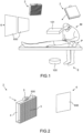
- FIG 1 schematically represents a radiology room in which there is a patient P and a medical staff M.
- the figure 1 further illustrates a radiological assembly E directed towards the patient P.
- the radiological assembly comprises an X-ray generator 100 and an X-ray detector 101.
- the patient P is placed between the X-ray generator 100 and the detector 101.
- the X-ray generator 100 is configured to generate an X-ray beam.
- the X-ray generator 100 and the detector 101 are positioned relative to each other such that X-rays emitted by the X-ray generator 100 are captured by the detector 101.
- the detector 101 is a traditional image detector.
- the image detector comprises in particular a sensor.
- the sensor is for example produced on a first substrate.
- the first substrate comprises a set of pixels organized in a matrix according to rows and columns.
- the matrix can comprise any number of rows and columns thus forming pixels.
- the matrix forms a geographical area on the first substrate. All of the pixels are configured so as to generate signals as a function of radiation arriving on the detector 101.
- the pixels comprise a photosensitive area delivering a current of electrical charges according to the flow of photons it receives, and an electronic circuit for processing this current.
- the photosensitive area generally comprises a photosensitive element, or photodetector, which may for example be a photodiode, a photoresistor or a phototransistor.
- the electronic circuit is made up for example of switches, capacitors, resistors, downstream of which an actuator is placed. The assembly made up of the photosensitive element and the electronic circuit makes it possible to generate electrical charges and to collect them.
- FIG 1 further represents two X-ray detection and visualization systems 2 according to an embodiment of the invention.
- the X-ray detection and visualization system 2 according to this exemplary embodiment is also individually represented in the figure 2 .
- the detection and visualization system 2 comprises a scattered X-ray detection assembly 1, an optical camera 5 and a reading and display device 6.
- the detection assembly 1 comprises an X-ray filtering device 3 and an X-ray imager 4.
- X-rays are a form of high-frequency electromagnetic radiation with wavelengths ranging from approximately 5 picometers to 10 nanometers. The energy of these photons ranges from a few eV (electron volts) to several tens of MeV.
- eV electron volts
- One of the main properties of X-rays is that they easily penetrate "soft matter” (solid matter that is not very dense and consists of light elements such as carbon, oxygen, and nitrogen) and are easily absorbed by "hard matter” (solid matter that is dense and consists of of heavy elements). This property allows medical imaging, the rays passing through the flesh and being stopped by the bones.
- the filtering device 3 is configured to filter X-rays.
- the filtered X-rays typically come from the scattered rays when a patient receives rays from the X-ray generator 100.
- the filtered X-rays come from the “primary” scattered rays, i.e. scattered by the patient receiving rays emitted by the X-ray generator 100 as well as by objects in the vicinity that are hit by the rays sent by the X-ray generator 100.
- the filtered X-rays may also be “secondary” scattered X-rays, i.e. resulting from the scattering by objects or personnel in the vicinity of the X-rays emitted by “primary” scattering.
- the filtering device 3 is assembled face to face with the imager 4, as shown schematically in the Figures 1 to 3 .
- the distance between the filtering device 3 and the imager 4 is small.
- the distance between the filtering device 3 and the imager 4 is less than 30 cm. This allows good detection of X-rays even when their flux is low.
- the filtering device 3 is here fixed to the imager 4.
- the filtering device 3 and the imager 4 have the same general shape.
- the part or surface of the filtering device 3 assembled to the imager 4 has the same dimensions as the imager 4.
- the imager 4 has for example a rectangular general shape.
- the filtering device 3 also has rectangular contours.
- the imager 4 is planar in the embodiment of the Figures 1 to 3 .
- the filtering device 3 is also planar.
- the imager 4 and the filtering device 3 are shown on the figure 1 a square shape.
- the imager 4 and the filtering device 3 each have a square shape with sides of 20 cm.
- the filtering device 3 and the imager 4 are parallel to each other.
- the imager 4 is configured to produce a radiographic image or X-ray image from the X-rays filtered by the filtering device 3.
- the imager 4 is for example similar to the X-ray detector 101.
- the imager 4 comprises in particular a sensor.
- the sensor is for example produced on a first substrate.
- the first substrate comprises a set of pixels organized in a matrix according to rows and columns.
- the matrix can comprise any number of rows and columns thus forming pixels.
- the matrix forms a geographical area on the first substrate. All of the pixels are configured so as to generate signals as a function of radiation arriving on the imager 4.
- the pixels are sensitive to X-rays and deliver an electrical signal (in particular an electrical charge) whose level is a function of the intensity of the X-rays.
- the pixels comprise a photosensitive element, or photodetector, which may for example be a photodiode, a photoresistor or a phototransistor.
- the electrical signals from the different pixels are collected by reading circuits of the imager 4 during a reading phase of the matrix and then digitized so as to be able to be processed and stored to form the X-ray image.
- Photosensitive elements are used to detect visible or near-visible electromagnetic radiation. These elements are not, or only slightly, sensitive to incident radiation at the detector. A radiation converter called a scintillator is then frequently used to convert the incident radiation, for example X-rays, into radiation in a wavelength band to which the photosensitive elements present in the pixels are sensitive.
- An alternative is to make the photosensitive element in another material that directly converts the X-rays into electrical charges. This is the case, for example, of matrices in which a first pixelated substrate made of Cadmium Telluride (CdTe) is connected pixel by pixel to a CMOS readout circuit that therefore no longer has the detection function.
- CdTe Cadmium Telluride
- the imager 4 is preferably very sensitive and low-noise. This is conventionally expressed by the value of the NED of the detector ("Noise Equivalent Dose", the dose whose X-ray noise is equal to the electronic noise of the imager 4).
- the signal received by the imager 4 in the case of an aperture of 1 cm 2 to 20 cm 2 and an X-ray dose sent to the patient by an X-ray source of intensity 10 mAs located 1 m from the patient, with an energy of 80 kV to 120 kV, could be only 0.01 to 0.05 nGy (nanoGray), which is very little.
- Imager 4 therefore has the capacity to produce readable images with doses of this order of magnitude, and its NED is typically less than or equal to 0.01 nGy. If the NED of Imager 4 is higher, the images from Imager 4 are averaged in time (temporal averaging, for example of 100 successive images) and/or in space (spatial averaging, for example in blocks of 10x10 pixels), which limits the temporal and/or spatial resolution, but brings the NED to the desired level.
- the filtering device 3 comprises a material capable of absorbing X-rays.
- the material capable of absorbing X-rays is, for example, lead, copper or tungsten. Copper has the advantage of being cheap, rigid and does not present a danger to the environment.
- the filtering device 3 shown schematically in Figures 1 and 2 according to one embodiment, is represented individually and from different viewing angles in figure 4 .
- the filtering device 3 comprises several blades 300, 301 (shown in the figures 4 , 5 ).
- the other figures represent the filtering device 3 in a very schematic manner.
- the blades 300, 301 comprise or are made of a material capable of absorbing X-rays (for example lead, copper or tungsten).
- the blades 300, 301 are oriented so as to absorb the X-rays in several directions.
- Each blade has a rectangular shape. Each blade thus has a longitudinal dimension or length, a lateral dimension or width, and a transverse dimension or thickness.
- the blades 300, 301 are here separated by spaces 302. In other words, a void separates the adjacent blades 300, 301 from each other.
- the blades 300, 301 are not separated by an empty space.
- the filtering device 3 comprises portions of material arranged between the blades 300, 301.
- the portions of material are made with a material transparent to X-rays.
- the portions of material also called transparent portions here
- the portions of material are, for example, portions of polyurethane foam.
- the blades 300, 301 comprise a first series of blades and a second series of blades.
- the first series of blades comprises first blades 300 succeeding one another in a first direction D1.
- the second series of blades comprises second blades 301 succeeding one another in a second direction D2.
- the first direction D1 and the second direction D2 are distinct, here orthogonal to each other.
- the blades 300, 301 are oriented so as to deviate from a center 303 of the filtering device 3.
- the first blades 300 are oriented so as to deviate from the center 303 of the filtering device 3 and the second blades 301 are oriented so as to deviate from the center 303 of the filtering device 3.
- the blades 300, 301 deviate from the center 303 in the direction from the imager 4 to the filtering device 3.
- the blades 300, 301 are oriented towards the outside of the filtering device 3.
- the blades 300, 301 thus configured, when the filtering device 3 is used with a radiological assembly, diverge from an X-ray generator.
- the blades 300, 301 are oriented so as to filter the X-rays in several directions.
- the blades 300, 301 are oriented at a non-zero orientation angle relative to the plane generated by the first direction D1 and the second direction D2.
- the blades 300, 301 are each oriented at a predefined orientation angle such that, for given blades 300, 301, X-rays arriving in certain directions are blocked by said given blades 300, 301. Said given blades 300, 301 absorb X-rays arriving in said directions. X-rays arriving in a different direction pass.
- the filtering device 3 comprises spaces 302 between the blades 300, 301
- the X-rays pass when they arrive in the space between two blades 300, 301.
- the X-rays which pass are those which do not arrive on a blade.
- the X-rays arriving in a given direction are absorbed by the blades 300, 301 except in a given part of the filtering device. 3 in which said X-rays pass between two blades 300, 301 and land on a given area of the imager 4.
- the operation of the filtering device 3 is similar when it comprises an X-ray transparent material in place of the empty spaces 302 between the blades 300, 301.
- each zone of the imager 4 sees only one direction of X-rays.
- the direction of X-rays seen by each zone of the imager 4 depends at least on the orientation of the blades 300, 301 of the filtering device 3.
- the orientation angle is modified along the filtering device 3.
- Several blades 300, 301 may have the same orientation angle.
- the orientation angles of the blades 300, 301 vary so as to absorb the X-rays in certain directions and allow them to pass in other directions.
- At least two of the first blades 300 are not parallel to each other and at least two of the second blades 301 are not parallel to each other.
- at least two of the first blades 300 have different orientation angles from each other and at least two of the second blades 301 have different orientation angles from each other.
- the filtering device 3 as described above forms an X-ray lens.
- the final radiographic image obtained by the imager 4 is an assembly of the images obtained by receiving the X-rays “sectioned” by the filtering device 3.
- the assembly of the images is carried out in the manner of a mosaic.
- the assembly of the images is similar to that made by insects having compound eyes.
- the number of blades 300, 301, their thickness and their orientation define the filtered image.
- the number of blades 300, 301, their thickness and their orientation are predefined and sized according to the need. These parameters define the gap (or even the space when there is one) between the blades 300, 301.
- the blades 300, 301 of the filtering device 3 have a thickness of between 0.1 mm and 5 mm, preferably approximately 1 mm.
- each blade 300, 301 is between 1 mm and 10 cm, preferably equal to 1 cm.
- each blade 300, 301 depends on the size of the imager 4 used.
- the length of each blade is less than or equal to the length of the imager 4, and preferably equal to the length of the imager 4.
- the length of each blade is between 1 cm and 50 cm, preferably equal to 20 cm.
- the orientation angle of the blades 300, 301 is between -90° and 90, preferably between -60° and 60°.
- the number of blades 300, 301 is between 10 and 1000, preferably around 100.
- the filtering device 3 plan in the examples of realization of the Figures 1 to 5 , has a depth, i.e. a total thickness, of between 1 and 10 cm.
- the filtering device 3 is thus very compact.
- the image X is also a function of the number of pixels of the imager 4 located opposite the spaces 302 between the blades 300, 301. Several pixels are preferably opposite each space 302 between the blades 300, 301.
- the filtering device 3 can be made in one piece, as is the case in the figure 4 .
- the filtering device 3 is made in two parts.
- the filtering device 3 comprises a first part 304 and a second part 305.
- the first part 304 comprises the first series of first blades 300.
- the second part 305 comprises the second series of second blades 301.
- the blades are each oriented according to a predefined orientation angle, similarly to the embodiment of the figure 4 .
- the first part 304 and the second part 305 can be superimposed as in the figure 5 .
- first part 304 and the second part 305 may be intersected.
- the construction of the filter device 3 in two parts is more economical than the construction in one piece.
- the filtering device 3 can be manufactured by 3D printing, by casting, or by any other means allowing to obtain the desired geometry and shapes.
- the filtering device 3 is preferably arranged at a distance from the area to be imaged of between 10 cm and 5 m, preferably of the order of 2 m. The smaller the distance, the better the quality of the radiographic image obtained.
- the imager 4 has the following advantage.
- the signal received by a pixel does not decrease with the distance between the imager 4 and the area to be imaged, provided that the area to be imaged is large enough and always covers the pixel.
- the X-ray signal decreases as 1/R 2 , R being the distance between the imager and the area to be imaged, but the area of the area that is imaged in a pixel increases as R 2 .
- the two effects compensate each other, and the signal is constant.
- the imager 4 may have a different shape, for example the imager 4 may be curved.
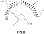
- the imager 4 may have a dome or half-sphere shape, as illustrated in figure 6 .
- the filtering device 3 has a similar shape, here a dome.
- the imager 4 and the filtering device 3 have the same characteristics as previously described for the imager 4 and the 3-plane filtering device.
- the filtering device 3 comprises several blades 300, 301 moving away from the center 303 of the filtering device 3 in the direction going from the imager 4 towards the filtering device 3.
- the filtering device 3 is also here attached to the imager 4.
- the dome or semi-spherical shape allows the imager 4 to capture more radiation compared to the flat shape.
- the dome may typically have a diameter of between 10 cm and 40 cm, for example 20 cm.
- the height may be between 5 cm and 20 cm, for example 10 cm.
- the radiographic image obtained depends as explained above on the configuration of the filtering device 3.
- the radiographic image is also a function of the number of pixels of the imager 4 located opposite the spaces 302 between the blades 300, 301 or the portions made of material transparent to radiation. Several pixels are preferably opposite each space. between the blades 300, 301, or with each portion made of material transparent to X-rays.
- Each pixel has dimensions of the order of a millimeter, or even a few millimeters. These dimensions are sufficient for the intended applications that do not require high image resolution.
- the optical camera 5, visible in figures 1, 2 , 3 And 5 is configured to produce an optical or visible image.
- the camera 5 includes a lens 500 and a CCD or CMOS photographic sensor 501.
- the imager 4 and the lens 500 of the optical camera 5 are directed toward the same point or the same area to be captured or imaged.
- the optical camera 5 has substantially the same field of vision as the imager 4.
- the imager 4 and the lens 500 of the camera 5 may be directed toward the areas or people exposed to the X-rays.
- the optical camera 5 is arranged in a plane parallel to the imager 4.
- the optical camera 5 can be arranged above the imager 4 ( figure 1 ).
- the optical camera 5 can be arranged at the center or focal point of the dome ( figure 6 ) or other curved shape.
- the reading and display device 6 is connected to the imager 4 and the camera 5.
- the reading and display device 6 is configured to read the X-ray image received from the imager 4 and the optical image received from the camera 5, superimpose the X-ray image and the optical image, and display the superposition of the X-ray image with the optical image.
- the reading and display device 6 comprises means of connection to the imager 4 and to the optical camera 5.
- the connection means are for example connectors or wireless connection means.
- the reading and display device 6 comprises an image reading and processing system.
- the reading and display device 6 may comprise a computer for image processing.
- the image processing may be performed by software enabling the optical image and the radiographic image to be combined.
- the reading and display device 6 further comprises a display 600, such as a monitor or screen for displaying the superposition of the radiographic image and of the optical image.
- the display 600 is connected to the image reading and processing system.
- the superposition of the X-ray image with the optical image shows the X-rays by displaying them on the optical image.
- the scattered X-rays can be visualized along with the location where they are scattered thanks to the superposition with the optical image.
- X-rays can be displayed in a different color than the optical image.
- the optical image can be black and white, and the X-rays in another color.
- Information of interest can also be displayed, such as the intensity of the X-rays.
- Numerical values of the intensity can be displayed and/or the X-rays can be displayed in different colors depending on their intensity.
- the areas diffusing the X-rays, as well as possibly other information such as their intensity, are displayed as an overlay on the optical image.
- the user can see this information appear in real time on the display 600. This could for example encourage him (in the case in particular of medical personnel) to protect himself from X-rays.
- One or more detection and visualization systems 2 may be used to detect and visualize the X-ray scattering areas. This improves the detection and visualization of the X-ray scattering areas.
- figure 1 represents two detection and visualization systems 2.
- a common display 600 may be used for multiple detection and visualization systems 2.
- the process of detecting and visualizing X-rays is as follows.
- the X-rays are filtered using an X-ray filtering device 3.
- the filtered X-rays are received by the imager 4.
- the X-ray image is produced by the imager 4 from the X-rays filtered by the filtering device 3.
- the optical camera 5 produces an optical image.
- Both the X-ray image and the optical image are read by means of the reading and display device 6 connected to the imager 4 and the camera 5.
- the reading and display device 6 for example by means of image processing software, superimposes the X-ray image and the optical image.
- the reading and display device 6 finally displays the superposition of the X-ray image and the optical image on the display 4.
- the reading and display device 6 can display other information such as the intensity of the X-rays.
- the detection assembly according to the invention allows, through a simple structure and configuration, to spatially filter the X-rays according to their emission direction. By its divergent configuration from the center of the filtering device, the latter allows the detection assembly to have a large field or large angle to capture the X-rays on the imager.
- the detection and visualization system allows to detect and visualize the X-ray diffusion zones so as to protect oneself from them for example.
- the display can be done in real time in order to provide live information on the diffusion of X-rays.
Landscapes
- Health & Medical Sciences (AREA)
- Life Sciences & Earth Sciences (AREA)
- Engineering & Computer Science (AREA)
- Medical Informatics (AREA)
- Physics & Mathematics (AREA)
- High Energy & Nuclear Physics (AREA)
- Molecular Biology (AREA)
- Biomedical Technology (AREA)
- Nuclear Medicine, Radiotherapy & Molecular Imaging (AREA)
- Optics & Photonics (AREA)
- General Health & Medical Sciences (AREA)
- Animal Behavior & Ethology (AREA)
- Public Health (AREA)
- Heart & Thoracic Surgery (AREA)
- Veterinary Medicine (AREA)
- Surgery (AREA)
- Radiology & Medical Imaging (AREA)
- Pathology (AREA)
- Biophysics (AREA)
- Spectroscopy & Molecular Physics (AREA)
- General Physics & Mathematics (AREA)
- Computer Vision & Pattern Recognition (AREA)
- General Engineering & Computer Science (AREA)
- Mathematical Physics (AREA)
- Apparatus For Radiation Diagnosis (AREA)
- Measurement Of Radiation (AREA)
Applications Claiming Priority (2)
| Application Number | Priority Date | Filing Date | Title |
|---|---|---|---|
| FR2304954A FR3148847B1 (fr) | 2023-05-17 | 2023-05-17 | Ensemble de détection de rayonnement ionisant diffusé et système de détection et de visualisation comportant ledit ensemble de détection. |
| FR2304953 | 2023-05-17 |
Publications (1)
| Publication Number | Publication Date |
|---|---|
| EP4465092A1 true EP4465092A1 (de) | 2024-11-20 |
Family
ID=91027403
Family Applications (1)
| Application Number | Title | Priority Date | Filing Date |
|---|---|---|---|
| EP24175605.5A Pending EP4465092A1 (de) | 2023-05-17 | 2024-05-14 | Anordnung zur detektion von streustrahlung und system zur detektion und visualisierung mit dieser detektoranordnung |
Country Status (3)
| Country | Link |
|---|---|
| US (1) | US20240385335A1 (de) |
| EP (1) | EP4465092A1 (de) |
| JP (1) | JP2024166163A (de) |
Citations (3)
| Publication number | Priority date | Publication date | Assignee | Title |
|---|---|---|---|---|
| EP1045398A2 (de) * | 1999-04-12 | 2000-10-18 | General Electric Company | Kollimator für Strahlungs-Bildaufnahmevorrichtung |
| US20190343471A1 (en) * | 2016-08-25 | 2019-11-14 | Koninklijke Philips N.V. | Variable focus x-ray anti scatter device |
| WO2022251701A1 (en) * | 2021-05-27 | 2022-12-01 | Sail Sv Llc | X-ray imaging system and method |
Family Cites Families (20)
| Publication number | Priority date | Publication date | Assignee | Title |
|---|---|---|---|---|
| US3921000A (en) * | 1973-02-16 | 1975-11-18 | Searle & Co | Gamma ray camera system with corrugated collimators |
| US4340818A (en) * | 1980-05-14 | 1982-07-20 | The Board Of Trustees Of The University Of Alabama | Scanning grid apparatus for suppressing scatter in radiographic imaging |
| SE423458B (sv) * | 1980-09-10 | 1982-05-03 | Agne Larsson | Anordning vid en kamera innefattande en manghalskollimator |
| GB9301206D0 (en) * | 1993-01-22 | 1993-03-17 | British Nuclear Fuels Plc | Gamma radiation camera systems |
| US6252938B1 (en) * | 1997-06-19 | 2001-06-26 | Creatv Microtech, Inc. | Two-dimensional, anti-scatter grid and collimator designs, and its motion, fabrication and assembly |
| US5949850A (en) * | 1997-06-19 | 1999-09-07 | Creatv Microtech, Inc. | Method and apparatus for making large area two-dimensional grids |
| US6771802B1 (en) * | 2000-04-13 | 2004-08-03 | Photon Imaging, Inc. | Method and apparatus for imaging and localizing radiation |
| US7922923B2 (en) * | 2001-02-01 | 2011-04-12 | Creatv Microtech, Inc. | Anti-scatter grid and collimator designs, and their motion, fabrication and assembly |
| FR2879304B1 (fr) * | 2004-12-14 | 2007-01-26 | Commissariat Energie Atomique | Dispositif d'imagerie gamma ameliore. |
| WO2008104915A2 (en) * | 2007-02-27 | 2008-09-04 | Philips Intellectual Property & Standards Gmbh | Simulation and visualization of scattered radiation |
| US20080304619A1 (en) * | 2007-06-07 | 2008-12-11 | General Electric Company | Modular Multi-Hole Collimators Method and System |
| US20100261997A1 (en) * | 2009-04-13 | 2010-10-14 | Baorui Ren | System and Method for Molecular Breast Imaging with Biopsy Capability and Improved Tissue Coverage |
| US7973276B2 (en) * | 2009-07-29 | 2011-07-05 | Ut-Battelle, Llc | Calibration method for video and radiation imagers |
| US8816292B2 (en) * | 2010-04-01 | 2014-08-26 | Hybridyne Imaging Technologies, Inc. | Compact endocavity diagnostic probes for nuclear radiation detection |
| US8957397B2 (en) * | 2011-09-26 | 2015-02-17 | Siemens Medical Solutions Usa, Inc. | Multilayer, multiaperture collimator for medical imaging and fabrication method |
| CN105520741A (zh) * | 2014-06-19 | 2016-04-27 | 武汉知微科技有限公司 | 多层错位耦合准直器、辐射器、探测装置及扫描设备 |
| US10143430B2 (en) * | 2015-06-18 | 2018-12-04 | The Cleveland Clinic Foundation | Systems and methods that use multi-modal imaging for enhanced resolution images |
| EP3420908A1 (de) * | 2017-06-27 | 2019-01-02 | Koninklijke Philips N.V. | Gestreute röntgenstrahluntersuchung zur detektion von missbrauch und verhütung von schäden |
| US20220023666A1 (en) * | 2018-12-10 | 2022-01-27 | University Health Network | Artificial neural network based radiotherapy safety system |
| KR102568800B1 (ko) * | 2020-07-06 | 2023-08-22 | 고려대학교 산학협력단 | 방사선 검출용 콜리메이터 및 이를 이용한 방사선 검출 장치 |
-
2024
- 2024-05-13 US US18/662,907 patent/US20240385335A1/en active Pending
- 2024-05-14 EP EP24175605.5A patent/EP4465092A1/de active Pending
- 2024-05-16 JP JP2024079937A patent/JP2024166163A/ja active Pending
Patent Citations (3)
| Publication number | Priority date | Publication date | Assignee | Title |
|---|---|---|---|---|
| EP1045398A2 (de) * | 1999-04-12 | 2000-10-18 | General Electric Company | Kollimator für Strahlungs-Bildaufnahmevorrichtung |
| US20190343471A1 (en) * | 2016-08-25 | 2019-11-14 | Koninklijke Philips N.V. | Variable focus x-ray anti scatter device |
| WO2022251701A1 (en) * | 2021-05-27 | 2022-12-01 | Sail Sv Llc | X-ray imaging system and method |
Non-Patent Citations (1)
| Title |
|---|
| AL MOHAMMAD, BADERAMONTHER GHARAIBEHMARAM AL ALAKHRAS: "Knowledge and practice of radiation protection in the operating theater among orthopédie surgeons", JOURNAL OF MEDICAL IMAGING, vol. 9, no. 6, 2022, pages 066002, XP060172042, DOI: 10.1117/1.JMI.9.6.066002 |
Also Published As
| Publication number | Publication date |
|---|---|
| JP2024166163A (ja) | 2024-11-28 |
| US20240385335A1 (en) | 2024-11-21 |
Similar Documents
| Publication | Publication Date | Title |
|---|---|---|
| US6868138B2 (en) | Method, processor and computed tomography (CT) machine for generating images utilizing high and low sensitivity data collected from a flat panel detector having an extended dynamic range | |
| US6448545B1 (en) | Precision endoscopic imaging system | |
| EP2288939B1 (de) | Verbesserte gammastrahlen-bildgebungseinrichtung zur genauen lokalisierung von bestrahlungsquellen im raum | |
| JP2022066564A (ja) | 複数のf値レンズのための方法およびシステム | |
| TWI825160B (zh) | 成像方法 | |
| US20050057744A1 (en) | Three-dimensional imaging with multiframe blind deconvolution | |
| US7135686B1 (en) | Low noise x-ray detector for fluoroscopy | |
| WO2006111678A1 (fr) | Dispositif limitant l'apparition d'artefacts de decodage pour gamma camera a masque code | |
| FR3024235A1 (fr) | Systeme d'imagerie planaire permettant la correction du diffuse | |
| EP3198625B1 (de) | Bimodale bilderfassungsvorrichtung mit photokathode | |
| FR2967887A1 (fr) | Mammographe compact, et procede de mammographie associe | |
| JP2022174229A (ja) | モノリシックシンチレータを有する多層検出器 | |
| WO2014154556A1 (fr) | Detecteur de traces de particules ionisantes | |
| JP2010223922A (ja) | X線撮像装置 | |
| US20130112879A1 (en) | Laser Viewing System | |
| Barrow et al. | A QuantumFilm based quadVGA 1.5 µm pixel image sensor with over 40% QE at 940 nm for actively illuminated applications | |
| EP4465092A1 (de) | Anordnung zur detektion von streustrahlung und system zur detektion und visualisierung mit dieser detektoranordnung | |
| Sollerman | The Crab pulsar and its red knot in the near-infrared | |
| Garanin et al. | Daytime observation of low-brightness stars (7^ m–8^ m) from level terrain | |
| FR3148847A1 (fr) | Ensemble de détection de rayonnement ionisant diffusé et système de détection et de visualisation comportant ledit ensemble de détection. | |
| FR2749699A1 (fr) | Collimateur a champ de vue multiple et systeme d'imagerie medicale comportant un tel collimateur | |
| EP4189373A1 (de) | Rückgestreute x-photonen-bildgebungsvorrichtung | |
| Drăgulinescu | Applications of CMOS image sensors: state-of-the-art | |
| US20130126711A1 (en) | Low light vision and thermal imaging devices with cool chip cooling | |
| Allanwood et al. | Point-spread function and photon transfer of a CCD for space-based astronomy |
Legal Events
| Date | Code | Title | Description |
|---|---|---|---|
| PUAI | Public reference made under article 153(3) epc to a published international application that has entered the european phase |
Free format text: ORIGINAL CODE: 0009012 |
|
| STAA | Information on the status of an ep patent application or granted ep patent |
Free format text: STATUS: THE APPLICATION HAS BEEN PUBLISHED |
|
| AK | Designated contracting states |
Kind code of ref document: A1 Designated state(s): AL AT BE BG CH CY CZ DE DK EE ES FI FR GB GR HR HU IE IS IT LI LT LU LV MC ME MK MT NL NO PL PT RO RS SE SI SK SM TR |
|
| STAA | Information on the status of an ep patent application or granted ep patent |
Free format text: STATUS: REQUEST FOR EXAMINATION WAS MADE |
|
| 17P | Request for examination filed |
Effective date: 20250516 |
|
| STAA | Information on the status of an ep patent application or granted ep patent |
Free format text: STATUS: EXAMINATION IS IN PROGRESS |