EP4465332A1 - Relais - Google Patents
Relais Download PDFInfo
- Publication number
- EP4465332A1 EP4465332A1 EP24176328.3A EP24176328A EP4465332A1 EP 4465332 A1 EP4465332 A1 EP 4465332A1 EP 24176328 A EP24176328 A EP 24176328A EP 4465332 A1 EP4465332 A1 EP 4465332A1
- Authority
- EP
- European Patent Office
- Prior art keywords
- contact
- movable contact
- movable
- piece
- push rod
- Prior art date
- Legal status (The legal status is an assumption and is not a legal conclusion. Google has not performed a legal analysis and makes no representation as to the accuracy of the status listed.)
- Pending
Links
- 230000003068 static effect Effects 0.000 claims abstract description 74
- 230000009471 action Effects 0.000 claims abstract description 14
- 238000000034 method Methods 0.000 description 7
- 239000000463 material Substances 0.000 description 4
- 238000005516 engineering process Methods 0.000 description 3
- 230000008569 process Effects 0.000 description 3
- 230000009286 beneficial effect Effects 0.000 description 2
- 239000000969 carrier Substances 0.000 description 2
- 230000009977 dual effect Effects 0.000 description 2
- 238000012986 modification Methods 0.000 description 2
- 230000004048 modification Effects 0.000 description 2
- BQCADISMDOOEFD-UHFFFAOYSA-N Silver Chemical compound [Ag] BQCADISMDOOEFD-UHFFFAOYSA-N 0.000 description 1
- 230000003247 decreasing effect Effects 0.000 description 1
- 238000011982 device technology Methods 0.000 description 1
- 238000001746 injection moulding Methods 0.000 description 1
- 238000009434 installation Methods 0.000 description 1
- 239000011810 insulating material Substances 0.000 description 1
- 238000004519 manufacturing process Methods 0.000 description 1
- 229910052709 silver Inorganic materials 0.000 description 1
- 239000004332 silver Substances 0.000 description 1
- 238000006467 substitution reaction Methods 0.000 description 1
- 230000007704 transition Effects 0.000 description 1
Images




Classifications
-
- H—ELECTRICITY
- H01—ELECTRIC ELEMENTS
- H01H—ELECTRIC SWITCHES; RELAYS; SELECTORS; EMERGENCY PROTECTIVE DEVICES
- H01H51/00—Electromagnetic relays
- H01H51/22—Polarised relays
- H01H51/2227—Polarised relays in which the movable part comprises at least one permanent magnet, sandwiched between pole-plates, each forming an active air-gap with parts of the stationary magnetic circuit
-
- H—ELECTRICITY
- H01—ELECTRIC ELEMENTS
- H01H—ELECTRIC SWITCHES; RELAYS; SELECTORS; EMERGENCY PROTECTIVE DEVICES
- H01H50/00—Details of electromagnetic relays
- H01H50/54—Contact arrangements
-
- H—ELECTRICITY
- H01—ELECTRIC ELEMENTS
- H01H—ELECTRIC SWITCHES; RELAYS; SELECTORS; EMERGENCY PROTECTIVE DEVICES
- H01H50/00—Details of electromagnetic relays
- H01H50/54—Contact arrangements
- H01H50/56—Contact spring sets
- H01H50/58—Driving arrangements structurally associated therewith; Mounting of driving arrangements on armature
-
- H—ELECTRICITY
- H01—ELECTRIC ELEMENTS
- H01H—ELECTRIC SWITCHES; RELAYS; SELECTORS; EMERGENCY PROTECTIVE DEVICES
- H01H1/00—Contacts
- H01H1/50—Means for increasing contact pressure, preventing vibration of contacts, holding contacts together after engagement, or biasing contacts to the open position
-
- H—ELECTRICITY
- H01—ELECTRIC ELEMENTS
- H01H—ELECTRIC SWITCHES; RELAYS; SELECTORS; EMERGENCY PROTECTIVE DEVICES
- H01H50/00—Details of electromagnetic relays
- H01H50/16—Magnetic circuit arrangements
-
- H—ELECTRICITY
- H01—ELECTRIC ELEMENTS
- H01H—ELECTRIC SWITCHES; RELAYS; SELECTORS; EMERGENCY PROTECTIVE DEVICES
- H01H50/00—Details of electromagnetic relays
- H01H50/16—Magnetic circuit arrangements
- H01H50/18—Movable parts of magnetic circuits, e.g. armature
-
- H—ELECTRICITY
- H01—ELECTRIC ELEMENTS
- H01H—ELECTRIC SWITCHES; RELAYS; SELECTORS; EMERGENCY PROTECTIVE DEVICES
- H01H50/00—Details of electromagnetic relays
- H01H50/44—Magnetic coils or windings
-
- H—ELECTRICITY
- H01—ELECTRIC ELEMENTS
- H01H—ELECTRIC SWITCHES; RELAYS; SELECTORS; EMERGENCY PROTECTIVE DEVICES
- H01H50/00—Details of electromagnetic relays
- H01H50/54—Contact arrangements
- H01H50/56—Contact spring sets
-
- H—ELECTRICITY
- H01—ELECTRIC ELEMENTS
- H01H—ELECTRIC SWITCHES; RELAYS; SELECTORS; EMERGENCY PROTECTIVE DEVICES
- H01H50/00—Details of electromagnetic relays
- H01H50/64—Driving arrangements between movable part of magnetic circuit and contact
-
- H—ELECTRICITY
- H01—ELECTRIC ELEMENTS
- H01H—ELECTRIC SWITCHES; RELAYS; SELECTORS; EMERGENCY PROTECTIVE DEVICES
- H01H9/00—Details of switching devices, not covered by groups H01H1/00 - H01H7/00
- H01H9/30—Means for extinguishing or preventing arc between current-carrying parts
- H01H9/38—Auxiliary contacts on to which the arc is transferred from the main contacts
-
- H—ELECTRICITY
- H01—ELECTRIC ELEMENTS
- H01H—ELECTRIC SWITCHES; RELAYS; SELECTORS; EMERGENCY PROTECTIVE DEVICES
- H01H50/00—Details of electromagnetic relays
- H01H50/64—Driving arrangements between movable part of magnetic circuit and contact
- H01H50/641—Driving arrangements between movable part of magnetic circuit and contact intermediate part performing a rectilinear movement
Definitions
- the present disclosure relates to the field of electronic control device technology, specifically to a relay.
- a relay is an electronic control device that has a control system (also known as an input circuit) and a controlled system (also known as an output circuit), and is typically used in automatic control circuits.
- the relay is an "automatic switch" that uses a smaller current to control a larger current. Therefore, it plays roles such as automatic regulation, safety protection, and circuit switching in electrical circuits.
- the relay includes a magnetic circuit part, a push rod assembly, and a contact part.
- the magnetic circuit part includes a coil assembly and an armature assembly. The coil assembly is used to drive the movement of the armature assembly, and then drive the contacts of the contact part to connect or disconnect through the push rod assembly.
- a relay according to the embodiment of the present disclosure includes:
- a contact gap between the movable contact unit and the static contact unit corresponding to each other in one set is smaller than a contact gap between the movable contact unit and the static contact unit corresponding to each other in the other set;
- the movable contact unit and the static contact unit in one set with a smaller contact gap is defined as an arc-resistant end contact, and movable contact unit and the static contact unit in the other set with a larger contact gap is defined as a current-carrying end contact;
- the movable contact unit includes one or more movable contacts
- the static contact unit includes one or more static contacts
- the movable contacts and static contacts corresponding to each other form a contact set
- the arc-resistant end contact includes one or more contact sets
- the current-carrying end contact includes one or more contact sets
- a number of the contact sets of the arc-resistant end contact is less than or equal to a number of the contact sets of the current-carrying end contact.
- the arc-resistant end contact includes one or two contact sets; and the current-carrying end contact includes two or three contact sets.
- the arc-resistant end contact includes two contact sets, and the two contact sets are arranged side by side in a width direction of the movable contact part;
- the current-carrying end contact includes two or three contact sets, and the two or three contact sets are arranged side by side in the width direction of the movable contact part.
- a slit is provided between the two movable contacts adjacent to each other on the movable contact piece in a width direction of the movable contact piece.
- one end of the slit penetrates through an end face of the movable contact piece, and the other end of the slit extends to the static contact on the movable contact piece.
- each set of movable contact parts further includes a movable contact leading-out piece, the movable contact leading-out piece is connected to the movable contact piece; the static contact unit is disposed at a connection position between the movable contact piece and the movable contact leading-out piece.
- the movable contact piece has a first end and a second end opposite to the first end in its own length direction;
- the magnetic circuit part includes a coil assembly and an armature assembly
- the armature assembly is pivotally connected to the base
- the armature assembly is connected to the push rod assembly
- the coil assembly is configured to drive the armature assembly to pivot.
- the movable contact piece includes a plurality of sub-contact pieces stacked with each other.
- the push rod assembly includes a first push rod and a second push rod, the first push rod and the second push rod being connected to two movable contact pieces, respectively.
- one of two movable contact pieces is deformed under an action of the push rod assembly and has an elastic force
- the elastic force makes the movable contact piece has a moving tendency to disconnect the contacts, thus the breaking force required by the this contact piece is smaller than that required by the other movable contact piece, so that on the premise that a total driving force provided by the push rod assembly remains unchanged, the breaking force provided by the push rod assembly to the other movable contact piece will increase.
- the breaking force of the push rod assembly can be differentiated according to different contact conditions, thereby reducing unnecessary energy loss and improving the utilization rate of the overall coil driving force.
- a relay according to the embodiments of the present disclosure includes a base 10, a pair of contact parts 20, a magnetic circuit part 30, and a push rod assembly 40.
- the pair of contact parts 20 and the magnetic circuit part 30 are disposed on the base 10
- the magnetic circuit part 30 drives contacts of the pair of contact parts 20 to connect or disconnect through the push rod assembly 40.
- a pair of contact parts 20 may be respectively disposed on two opposite sides of the magnetic circuit part 30.
- the pair of the contact parts 20 may also be disposed on the same side of the magnetic circuit part 30.
- Each contact part 20 includes two sets of movable contact parts 20a.
- Each set of movable contact parts 20a includes a movable contact piece 210, a movable contact unit 220, a static contact unit 230, and a movable contact leading-out piece 240.
- the movable contact piece 210 is connected to the movable contact leading-out piece 240.
- the movable contact unit 220 is disposed on the movable contact piece 210, and the static contact unit 230 is disposed on the movable contact piece 210 and/or the movable contact leading-out piece 240.
- Two movable contact units 220 of each contact part 20 correspond to two static contact units 230 of each contact part 20, respectively.
- the movable contact leading-out piece 240 is fixedly connected to the base 10.
- the magnetic circuit part 30 is disposed on the base 10 and is used to drive the movement of four movable contact pieces 210 of the pair of contact parts 20 through the push rod assembly 40, thereby connecting and disconnecting the movable contact units 220 and the static contact units 230.
- the relay of the embodiments of the present disclosure includes a pair of contact parts 20.
- Each contact part 20 can control one circuit, so that the relay of the embodiments of the present disclosure can control at least two circuits.
- the relay may include only one contact part 20, which can control one circuit, thereby enabling the relay to control one circuit.
- a contact gap between the corresponding movable contact unit 220 and static contact unit 230 in one set is smaller than a contact gap between the corresponding movable contact unit 220 and static contact unit 230 in the other set.
- a contact gap between the movable contact unit 220 and the static contact unit 230 on the right side is H3
- the contact gap between the movable contact unit 220 and the static contact unit 230 on the left side is H4, where H3 ⁇ H4.
- a contact height of the movable contact unit 220 and the static contact unit 230 on the right side is smaller than a contact height of the movable contact unit 220 and the static contact unit 230 on the left side, so that when the contact part 20 is in the disconnected state, due to the smaller contact height on the right side compared to the left side, the contact gap between the movable contact unit 220 and the static contact unit 230 on the right side is larger, and greater than the contact gap on the left side.
- the set of the movable contact unit 220 and the static contact unit 230 with the larger contact gap plays a current-carrying role, while the set of the movable contact unit 220 and the static contact unit 230 with the smaller contact gap plays an arc-resistant role. Since the set of the movable contact unit 220 and the static contact unit 230 with the larger contact gap does not produce an arc when disconnecting. Therefore, only the set of the movable contact unit 220 and the static contact unit 230 with the smaller contact gap needs to be controlled for the contact parameters of the entire contact part 20, without considering the set of the movable contact unit 220 and the static contact unit 230 with the larger contact gap. Compared to the multi-contact design in the existing technology, the contact parameters of the contact part 20 of the embodiments of the present disclosure are easier to control and simpler to process, which is beneficial for improving production efficiency.
- the static contact unit 230 is disposed at a connection position between the movable contact piece 210 and the movable contact leading-out piece 240.
- the movable contact piece 210 has a first end 210a and a second end 210b opposite to each other along its own length direction D1.
- the movable contact unit 220 is disposed at the first end 210a
- the static contact unit 230 is disposed at the second end 210b.
- the second end 210b of the movable contact piece 210 is connected to the movable contact leading-out piece 240, so that the static contact unit 230 is disposed at a connection position between the second end 210b of the movable contact piece 210 and the movable contact leading-out piece 240.
- two movable contact pieces 210 are parallel with each other.
- the movable contact unit 220 at the first end 210a of one of the movable contact pieces 210 corresponds to the static contact unit 230 at the second end 210b of the other of the movable contact pieces 210, such that two pairs of the movable contact units 220 and the static contact units 230 after being connected form a circuit structure in parallel.
- the design of the contact part 20 as a parallel circuit structure can effectively reduce a temperature rise.
- the push rod assembly 40 includes a first push rod 410 and a second push rod 420, which are respectively disposed on the other two opposite sides of the magnetic circuit part 30.
- the magnetic circuit part 30 is drivably connected with the first push rod 410 and the second push rod 420, respectively, so as to drive the first push rod 410 and the second push rod 420 to reciprocate.
- One end of the first push rod 410 is connected to the first end 210a of one of the movable contact pieces 210 in one of the contact parts 20, and the other end of the first push rod 410 is connected to the first end 210a of the other of the movable contact pieces 210 in the other of the contact parts 20.
- the one end of the second push rod 420 is connected to the first end 210a of the other of the movable contact pieces 210 in one of the contact parts 20, and the other end of the second push rod 420 is connected to the first end 210a of the other of the movable contact pieces 210 in the other of the contact parts 20.
- the movement directions of the first push rod 410 and the second push rod 420 are opposite. If the first push rod 410 moves downwards, then the second push rod 420 moves upwards. Since the first push rod 410 moves downwards, the two movable contact pieces 210 connected to the first push rod 410 both pivot downwards around their respective second ends 210b. Since the second push rod 420 moves upwards, the two movable contact pieces 210 connected to the second push rod 420 both pivot upwards around their respective second ends 210b. In one contact part 20, the two movable contact pieces 210 pivot in opposite directions and move away from each other, thereby achieving the disconnection of the movable contact unit 220 and the static contact unit 230.
- the two movable contact pieces 210 connected to the first push rod 410 both pivot upwards around their respective second ends 210b, and the two movable contact pieces 210 connected to the second push rod 420 both pivot downwards around their respective second ends 210b.
- the two movable contact pieces 210 pivot in opposite directions and move towards each other, achieving the connection of the movable contact unit 220 and the static contact unit 230.
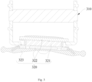
- the magnetic circuit part 30 includes a coil assembly 310 and an armature assembly 320, the armature assembly 320 is pivotally connected to the base 10.
- the coil assembly 310 is used to drive the armature assembly 320 to pivot relative to the base 10.
- the armature assembly 320 includes a permanent magnet 321, an armature 322, and a swinging arm 323. There are two armatures 322, and the permanent magnet 321 is clamped between the two armatures 322.
- the swinging arm 323 may be made of an insulating material, such as plastic.
- the permanent magnet 321, the armature 322, and the swinging arm 323 may be integrally connected by an injection molding. Two ends of the swinging arm 323 are respectively connected to the first push rod 410 and the second push rod 420.
- the swinging arm 323 of the armature assembly 320 respectively drive the reciprocated movement of the first push rod 410 and the second push rod 420, so as to achieve the connection or disconnection of the movable contact unit 220 and the static contact unit 230.
- two movable contact pieces 210 under the magnetic circuit part 30 in Fig. 2 are defined as the first movable contact piece 210c and the second movable contact piece 210d respectively, and two movable contact pieces 210 upper the magnetic circuit part 30 in Fig. 2 are defined as the third movable contact piece 210e and the fourth movable contact piece 210f.
- one end of the first push rod 410 is connected with the first end 210a of the first movable contact piece 210c, and the other end of the first push rod 410 is connected with the first end 210a of the fourth movable contact piece 210f.
- One end of the second push rod 420 is connected with the first end 210a of the second movable contact piece 210d, and the other end of the second push rod 420 is connected with the first end 210a of the third movable contact piece 210e.
- the first push rod 410 is used to drive the first movable contact piece 210c and the fourth movable contact piece 210f to pivot about their respective second ends 210b
- the second push rod 420 is used to drive the second movable contact piece 210d and the third movable contact piece 210e to pivot about their respective second ends 210b.
- the coil assembly 310 after being energized, can drive the armature assembly 320 to pivot relative to the base 10. For example, when the coil assembly 310 passes a positive current, the armature assembly 320 pivots clockwise; when the coil assembly 310 passes a negative current, the armature assembly 320 pivots counterclockwise.
- a coil driving force generated by the energized coil assembly 310 overcomes a magnetic holding force of the permanent magnet 321 and elastic forces of the four movable contact pieces 210 connected to the first push rod 410 and the second push rod 420, respectively. Only when the coil driving force is greater than a sum of the magnetic holding force and the elastic forces, can the armature assembly 320 pivot.
- the elastic force F makes the first movable contact piece 210c has a moving tendency to disconnect the contacts.
- the third movable contact piece 210e is deformed under the action of the second push rod 420 and has an elastic force F, the elastic force F makes the third movable contact piece 210e has a moving tendency to disconnect the contacts.
- the first push rod 410 pushes the first movable contact piece 210c to pivot downward, the second push rod 420 pushes the third movable contact piece 210e to pivot upward; At the same time, the first push rod 410 pulls the fourth movable contact piece 210f to pivot downward, the second push rod 420 pulls the second movable contact piece 210d to pivot upward.
- the relay in the embodiment of the present disclosure can perform differential treatment on the breaking force of two push rods according to different contact conditions, thereby reducing unnecessary energy loss and improving the utilization rate of the overall coil driving force.
- the set of the movable contact unit 220 and the static contact unit 230 with a smaller contact gap is defined as an arc-resistant end contact 250, and the set of the movable contact unit 220 and the static contact unit 230 with a larger contact gap is defined as a current-carrying end contact 260.
- the movable contact piece 210 provided with the movable contact unit of the current-carrying end contact 260 is defined as the first movable contact piece 210c
- the movable contact piece 210 provided with the movable contact unit of the arc-resistant end contact is defined as the second movable contact piece 210d.
- the contact gap between the arc-resistant end contact 250 is smaller, it is prone to generate an adhesion force when the contacts are disconnected, which may cause the relay to fail to disconnect reliably. Therefore, compared to the current-carrying end contact 260, the arc-resistant end contact 250 requires a greater driving force to achieve reliable disconnection.
- the contacts formed the contact gaps H4 and H2 are the current-carrying end contacts 260, the contacts formed the contact gaps H1and H3 are the arc-resistant end contacts 250.
- the elastic force F makes the movable contact piece 210 has a moving tendency to disconnect the contacts. Therefore, during the contact part 20 transits from the connected state to the disconnected state, the current-carrying end contact 260 corresponding to the contact gap H4 only needs smaller breaking force provided by the first push rod 410 for breaking.
- the third movable contact piece 210e is deformed under the action of the second push rod 420 and has an elastic force F, the elastic force F makes the third movable contact piece 210e has a moving tendency to disconnect the contacts. Therefore, during the contact part 20 transits from the connected state to the disconnected state, the current-carrying end contact 260 corresponding to the contact gap H2 only needs smaller breaking force provided by the second push rod 420 for breaking.
- the relay of the embodiments of the present disclosure has both advantages of being easy to control the parameters of the arc-resistant end contact 250 without considering the parameters of the current-carrying end contact 260, and improving the reliability of breaking the arc-resistant end contact 250.
- the movable contact unit 220 and the static contact unit 230 on the left side are defined as the arc-resistant end contact 250, and the movable contact unit 220 and the static contact unit 230 on the right side are defined as the current-carrying end contact 260; in the contact part 20 located below the magnetic circuit part 30, the movable contact unit 220 and the static contact unit 230 on the right side are defined as the arc-resistant end contact 250, and the movable contact unit 220 and the static contact unit 230 on the left side are defined as the current-carrying end contact 260.
- two arc-resistant end contacts 250 are located on a diagonal line of the base 10.
- Two ends of the first push rod 410 respectively correspond to one current-carrying end contact 260 and one arc-resistant end contact 250
- the two ends of the second push rod 420 respectively correspond to one current-carrying end contact 260 and one arc-resistant end contact 250.
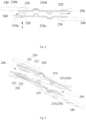
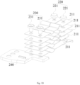
- the movable contact piece 210 includes a plurality of sub-contact pieces 211 stacked with each other.
- the thickness of the sub-contact pieces 211 is thin, and the movable contact piece 210 can be made of a thin strip material with lower material cost; on the other hand, by increasing or decreasing the number of the sub-contact piece 211, the thickness of the movable contact piece 210 can be changed, which is convenient for operation.
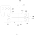
- the movable contact unit 220 includes one or more movable contacts 221, and the static contact unit 230 includes one or more static contacts 231.
- the movable contact 221 and the static contact 231 corresponding to each other form a contact set.
- the arc-resistant end contact 250 includes one or more contact sets.
- the current-carrying end contact 260 includes one or more contact sets. The number of the contact sets in the arc-resistant end contacts 250 is less than or equal to the number of contact sets in the current-carrying end contact 260.
- both the arc-resistant end contact 250 and the current-carrying end contact 260 may respectively be configured to include a plurality of contact sets, such that a parallel structure formed by the plurality of contact sets can further reduce a temperature rise of the relay.
- the number of the contact sets in the arc-resistant end contact 250 is designed to be less than or equal to the number of the contact sets in the current-carrying end contact 260.
- This not only increases the number of the contact sets in the current-carrying end contact 260 to reduce the temperature rise but also controls the number of the contact sets in the arc-resistant end contact 250, facilitating the management of contact parameters, ultimately achieving a situation where the increase in the contact sets does not affect the management of the contact parameters.
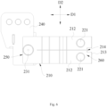
- the contact part 20 includes three sets of contact sets, among which the number of contact sets of the arc-resistant end contact 250 is 1, and the number of contact sets of the current-carrying end contact 260 is 2.
- the two contact sets of the current-carrying end contact 260 are arranged side by side along a width direction D2 of the movable contact piece 210.
- a slit 214 is provided between the two movable contacts 221 adjacent to each other on the movable contact piece 210. Furthermore, along a length direction D1 of the movable contact piece 210, one end of the slit 214 penetrates through an end face 213 of the movable contact piece 210, and the other end of the slit 214 extends to the static contact 231 on the movable contact piece 210.
- a slit 214 may not be provided on the movable contact piece 210.
- the movable contacts 221 and the static contacts 231 are provided on the movable contact pieces 210. It can be understood that the movable contacts 221 may be connected to the movable contact pieces 210 in an integral or separate manner, and the static contacts 231 can also be connected to the movable contact pieces 210 in an integral or separate manner.
- connection method may be riveting, but this is not limited thereto.
- the movable contact pieces 210 may also be an integral piece, without the multi-layer sub-contact pieces 211 stacked with each other.
- the arc-resistant end contact since the number of contact set is small, the volume of each contact can be designed to be larger, and the silver layer arranged on the contact is more resistant to burning, which improves the durability of the contact. Moreover, the arc-resistant end contact has fewer contact sets, which is convenient for measuring contact parameters. For the current-carrying end contact, there are more contact sets, forming a multi-contact parallel structure, thereby reducing the temperature rise.
- the contact part 20 of the second embodiment has a substantially similar structure in the basic configuration. Therefore, in the following description of the contact part 20 of the second embodiment, the structures already described in the first embodiment will not be repeated. In addition, the structures in the contact part 20 of the second embodiment that are the same as those described in the first embodiment will be denoted by the same reference numerals. Therefore, in the following description of the present embodiment, the differences between the contact part 20 of the second embodiment and the contact part 20 of the first embodiment will be mainly described.
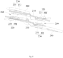
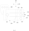
- the contact part 20 includes four sets of contacts, among which the number of contact sets of the arc-resistant end contact 250 is 2, and the number of contact sets of the current-carrying end contact 260 is 2.
- the two contact sets of the arc-resistant end contact 250 and the two contact sets of the current-carrying end contact 260 are respectively arranged along the width direction D2 of the movable contact piece 210.
- the movable contact piece 210 may be provided with a slit 214, or not.
- the contact part 20 of the third embodiment has a substantially similar structure in its basic configuration. Therefore, in the following description of the contact part 20 of the third embodiment, the structures already described in the second embodiment will not be repeated. In addition, the structures in the contact part 20 of the third embodiment that are the same as those described in the second embodiment will be denoted by the same reference numerals. Therefore, in the following description of the present embodiment, the differences between the contact part 20 of the third embodiment and the contact part 20 of the second embodiment will be mainly described.
- the contact part 20 of the fourth embodiment has a substantially similar structure in its basic configuration. Therefore, in the following description of the contact part 20 of the fourth embodiment, the structures already described in the first embodiment will not be repeated. In addition, the structures in the contact part 20 of the fourth embodiment that are the same as those described in the first embodiment will be denoted by the same reference numerals. Therefore, in the following description of the present embodiment, the differences between the contact part 20 of the fourth embodiment and the contact part 20 of the first embodiment will be mainly described.
- the arc-resistant end contact 250 two sets of contacts are arranged side by side along the width direction D2 of the movable contact piece 210.
- the current-carrying end contact 260 three sets of contacts are arranged side by side along the width direction D2 of the movable contact piece 210.
- connection can be a fixed connection, or a removable connection, or an integral connection; “connected” can be directly connected, or indirectly connected through an intermediary medium.
- connection can be a fixed connection, or a removable connection, or an integral connection; “connected” can be directly connected, or indirectly connected through an intermediary medium.
Landscapes
- Physics & Mathematics (AREA)
- Electromagnetism (AREA)
- Contacts (AREA)
- Arc-Extinguishing Devices That Are Switches (AREA)
Applications Claiming Priority (1)
| Application Number | Priority Date | Filing Date | Title |
|---|---|---|---|
| CN202310565158.2A CN119008327A (zh) | 2023-05-18 | 2023-05-18 | 继电器 |
Publications (1)
| Publication Number | Publication Date |
|---|---|
| EP4465332A1 true EP4465332A1 (de) | 2024-11-20 |
Family
ID=91129499
Family Applications (1)
| Application Number | Title | Priority Date | Filing Date |
|---|---|---|---|
| EP24176328.3A Pending EP4465332A1 (de) | 2023-05-18 | 2024-05-16 | Relais |
Country Status (4)
| Country | Link |
|---|---|
| US (1) | US20240387135A1 (de) |
| EP (1) | EP4465332A1 (de) |
| JP (1) | JP7772131B2 (de) |
| CN (1) | CN119008327A (de) |
Citations (3)
| Publication number | Priority date | Publication date | Assignee | Title |
|---|---|---|---|---|
| EP2752862A1 (de) * | 2011-02-11 | 2014-07-09 | Clodi L.L.C. | Bistabiles elektromagnetisches Relais mit einem X-Drive-Motor |
| EP2940704A1 (de) * | 2014-05-01 | 2015-11-04 | Johnson Electric S.A. | Verbesserungen in elektrischen kontaktsätzen |
| US20180240631A1 (en) * | 2015-10-29 | 2018-08-23 | Omron Corporation | Relay |
Family Cites Families (2)
| Publication number | Priority date | Publication date | Assignee | Title |
|---|---|---|---|---|
| EP3547344B1 (de) * | 2016-11-25 | 2021-11-10 | Xiamen Hongfa Electric Power Controls Co., Ltd. | Magnetverriegelungsrelais mit widerstandsfähigkeit gegen kurzschlussstrom |
| CN106971913B (zh) | 2017-04-01 | 2018-09-21 | 厦门宏发电力电器有限公司 | 一种能够抵抗短路电流的磁保持继电器 |
-
2023
- 2023-05-18 CN CN202310565158.2A patent/CN119008327A/zh active Pending
-
2024
- 2024-05-16 EP EP24176328.3A patent/EP4465332A1/de active Pending
- 2024-05-17 JP JP2024081263A patent/JP7772131B2/ja active Active
- 2024-05-18 US US18/668,132 patent/US20240387135A1/en active Pending
Patent Citations (3)
| Publication number | Priority date | Publication date | Assignee | Title |
|---|---|---|---|---|
| EP2752862A1 (de) * | 2011-02-11 | 2014-07-09 | Clodi L.L.C. | Bistabiles elektromagnetisches Relais mit einem X-Drive-Motor |
| EP2940704A1 (de) * | 2014-05-01 | 2015-11-04 | Johnson Electric S.A. | Verbesserungen in elektrischen kontaktsätzen |
| US20180240631A1 (en) * | 2015-10-29 | 2018-08-23 | Omron Corporation | Relay |
Also Published As
| Publication number | Publication date |
|---|---|
| CN119008327A (zh) | 2024-11-22 |
| JP2024166189A (ja) | 2024-11-28 |
| KR20240166953A (ko) | 2024-11-26 |
| JP7772131B2 (ja) | 2025-11-18 |
| US20240387135A1 (en) | 2024-11-21 |
Similar Documents
| Publication | Publication Date | Title |
|---|---|---|
| US11710606B2 (en) | Dual parallel moveable electrical contacts/relays | |
| CN219873348U (zh) | 继电器 | |
| EP4465323A1 (de) | Relais | |
| CN219040365U (zh) | 触头结构和继电器 | |
| EP4465332A1 (de) | Relais | |
| CN219873341U (zh) | 接触部分及继电器 | |
| EP4465333B1 (de) | Relais | |
| CN115132524A (zh) | 双电磁回路控制的具有串联和并联触头的继电器 | |
| EP4465325A1 (de) | Kontaktteil und relais | |
| CN219873347U (zh) | 继电器 | |
| KR102827387B1 (ko) | 차량용 콘택터, 차량 충전 및 전력 분배 시스템, 충전 파일, 및 차량 | |
| CN219873346U (zh) | 继电器 | |
| KR102958633B1 (ko) | 릴레이 | |
| KR102954494B1 (ko) | 릴레이 | |
| US20240387136A1 (en) | Relay | |
| CN117809995A (zh) | 切换开关 | |
| EP4465334A1 (de) | Relais | |
| CN220914122U (zh) | 一种继电器及车辆 | |
| CN222319995U (zh) | 一种触头组件、负荷开关及电表 | |
| CN219873331U (zh) | 继电器 | |
| CN223193721U (zh) | 继电器 | |
| CN119008325A (zh) | 继电器 | |
| KR20260032336A (ko) | 예비충전 릴레이를 갖는 다중 스위치 접촉기 조립체 | |
| CN121768914A (zh) | 继电器 |
Legal Events
| Date | Code | Title | Description |
|---|---|---|---|
| PUAI | Public reference made under article 153(3) epc to a published international application that has entered the european phase |
Free format text: ORIGINAL CODE: 0009012 |
|
| STAA | Information on the status of an ep patent application or granted ep patent |
Free format text: STATUS: REQUEST FOR EXAMINATION WAS MADE |
|
| 17P | Request for examination filed |
Effective date: 20240516 |
|
| AK | Designated contracting states |
Kind code of ref document: A1 Designated state(s): AL AT BE BG CH CY CZ DE DK EE ES FI FR GB GR HR HU IE IS IT LI LT LU LV MC ME MK MT NL NO PL PT RO RS SE SI SK SM TR |