EP4465425A1 - Vollständig eingetauchte energiespeichervorrichtung - Google Patents
Vollständig eingetauchte energiespeichervorrichtung Download PDFInfo
- Publication number
- EP4465425A1 EP4465425A1 EP23794232.1A EP23794232A EP4465425A1 EP 4465425 A1 EP4465425 A1 EP 4465425A1 EP 23794232 A EP23794232 A EP 23794232A EP 4465425 A1 EP4465425 A1 EP 4465425A1
- Authority
- EP
- European Patent Office
- Prior art keywords
- energy storage
- storage device
- motor
- fully immersed
- assembly
- Prior art date
- Legal status (The legal status is an assumption and is not a legal conclusion. Google has not performed a legal analysis and makes no representation as to the accuracy of the status listed.)
- Granted
Links
Images



Classifications
-
- H—ELECTRICITY
- H01—ELECTRIC ELEMENTS
- H01M—PROCESSES OR MEANS, e.g. BATTERIES, FOR THE DIRECT CONVERSION OF CHEMICAL ENERGY INTO ELECTRICAL ENERGY
- H01M10/00—Secondary cells; Manufacture thereof
- H01M10/60—Heating or cooling; Temperature control
- H01M10/65—Means for temperature control structurally associated with the cells
- H01M10/656—Means for temperature control structurally associated with the cells characterised by the type of heat-exchange fluid
- H01M10/6567—Liquids
- H01M10/6568—Liquids characterised by flow circuits, e.g. loops, located externally to the cells or cell casings
-
- H—ELECTRICITY
- H01—ELECTRIC ELEMENTS
- H01M—PROCESSES OR MEANS, e.g. BATTERIES, FOR THE DIRECT CONVERSION OF CHEMICAL ENERGY INTO ELECTRICAL ENERGY
- H01M10/00—Secondary cells; Manufacture thereof
- H01M10/60—Heating or cooling; Temperature control
- H01M10/61—Types of temperature control
- H01M10/613—Cooling or keeping cold
-
- H—ELECTRICITY
- H01—ELECTRIC ELEMENTS
- H01M—PROCESSES OR MEANS, e.g. BATTERIES, FOR THE DIRECT CONVERSION OF CHEMICAL ENERGY INTO ELECTRICAL ENERGY
- H01M10/00—Secondary cells; Manufacture thereof
- H01M10/60—Heating or cooling; Temperature control
- H01M10/64—Heating or cooling; Temperature control characterised by the shape of the cells
- H01M10/647—Prismatic or flat cells, e.g. pouch cells
-
- H—ELECTRICITY
- H01—ELECTRIC ELEMENTS
- H01M—PROCESSES OR MEANS, e.g. BATTERIES, FOR THE DIRECT CONVERSION OF CHEMICAL ENERGY INTO ELECTRICAL ENERGY
- H01M10/00—Secondary cells; Manufacture thereof
- H01M10/60—Heating or cooling; Temperature control
- H01M10/65—Means for temperature control structurally associated with the cells
- H01M10/655—Solid structures for heat exchange or heat conduction
- H01M10/6556—Solid parts with flow channel passages or pipes for heat exchange
-
- H—ELECTRICITY
- H01—ELECTRIC ELEMENTS
- H01M—PROCESSES OR MEANS, e.g. BATTERIES, FOR THE DIRECT CONVERSION OF CHEMICAL ENERGY INTO ELECTRICAL ENERGY
- H01M10/00—Secondary cells; Manufacture thereof
- H01M10/60—Heating or cooling; Temperature control
- H01M10/65—Means for temperature control structurally associated with the cells
- H01M10/656—Means for temperature control structurally associated with the cells characterised by the type of heat-exchange fluid
- H01M10/6567—Liquids
-
- H—ELECTRICITY
- H01—ELECTRIC ELEMENTS
- H01M—PROCESSES OR MEANS, e.g. BATTERIES, FOR THE DIRECT CONVERSION OF CHEMICAL ENERGY INTO ELECTRICAL ENERGY
- H01M10/00—Secondary cells; Manufacture thereof
- H01M10/60—Heating or cooling; Temperature control
- H01M10/65—Means for temperature control structurally associated with the cells
- H01M10/656—Means for temperature control structurally associated with the cells characterised by the type of heat-exchange fluid
- H01M10/6569—Fluids undergoing a liquid-gas phase change or transition, e.g. evaporation or condensation
-
- H—ELECTRICITY
- H01—ELECTRIC ELEMENTS
- H01M—PROCESSES OR MEANS, e.g. BATTERIES, FOR THE DIRECT CONVERSION OF CHEMICAL ENERGY INTO ELECTRICAL ENERGY
- H01M10/00—Secondary cells; Manufacture thereof
- H01M10/60—Heating or cooling; Temperature control
- H01M10/65—Means for temperature control structurally associated with the cells
- H01M10/658—Means for temperature control structurally associated with the cells by thermal insulation or shielding
-
- H—ELECTRICITY
- H01—ELECTRIC ELEMENTS
- H01M—PROCESSES OR MEANS, e.g. BATTERIES, FOR THE DIRECT CONVERSION OF CHEMICAL ENERGY INTO ELECTRICAL ENERGY
- H01M50/00—Constructional details or processes of manufacture of the non-active parts of electrochemical cells other than fuel cells, e.g. hybrid cells
- H01M50/20—Mountings; Secondary casings or frames; Racks, modules or packs; Suspension devices; Shock absorbers; Transport or carrying devices; Holders
- H01M50/204—Racks, modules or packs for multiple batteries or multiple cells
- H01M50/207—Racks, modules or packs for multiple batteries or multiple cells characterised by their shape
- H01M50/209—Racks, modules or packs for multiple batteries or multiple cells characterised by their shape adapted for prismatic or rectangular cells
-
- H—ELECTRICITY
- H01—ELECTRIC ELEMENTS
- H01M—PROCESSES OR MEANS, e.g. BATTERIES, FOR THE DIRECT CONVERSION OF CHEMICAL ENERGY INTO ELECTRICAL ENERGY
- H01M50/00—Constructional details or processes of manufacture of the non-active parts of electrochemical cells other than fuel cells, e.g. hybrid cells
- H01M50/20—Mountings; Secondary casings or frames; Racks, modules or packs; Suspension devices; Shock absorbers; Transport or carrying devices; Holders
- H01M50/244—Secondary casings; Racks; Suspension devices; Carrying devices; Holders characterised by their mounting method
-
- H—ELECTRICITY
- H01—ELECTRIC ELEMENTS
- H01M—PROCESSES OR MEANS, e.g. BATTERIES, FOR THE DIRECT CONVERSION OF CHEMICAL ENERGY INTO ELECTRICAL ENERGY
- H01M50/00—Constructional details or processes of manufacture of the non-active parts of electrochemical cells other than fuel cells, e.g. hybrid cells
- H01M50/20—Mountings; Secondary casings or frames; Racks, modules or packs; Suspension devices; Shock absorbers; Transport or carrying devices; Holders
- H01M50/262—Mountings; Secondary casings or frames; Racks, modules or packs; Suspension devices; Shock absorbers; Transport or carrying devices; Holders with fastening means, e.g. locks
- H01M50/264—Mountings; Secondary casings or frames; Racks, modules or packs; Suspension devices; Shock absorbers; Transport or carrying devices; Holders with fastening means, e.g. locks for cells or batteries, e.g. straps, tie rods or peripheral frames
-
- H—ELECTRICITY
- H01—ELECTRIC ELEMENTS
- H01M—PROCESSES OR MEANS, e.g. BATTERIES, FOR THE DIRECT CONVERSION OF CHEMICAL ENERGY INTO ELECTRICAL ENERGY
- H01M10/00—Secondary cells; Manufacture thereof
- H01M10/42—Methods or arrangements for servicing or maintenance of secondary cells or secondary half-cells
- H01M10/48—Accumulators combined with arrangements for measuring, testing or indicating the condition of cells, e.g. the level or density of the electrolyte
- H01M10/486—Accumulators combined with arrangements for measuring, testing or indicating the condition of cells, e.g. the level or density of the electrolyte for measuring temperature
-
- H—ELECTRICITY
- H01—ELECTRIC ELEMENTS
- H01M—PROCESSES OR MEANS, e.g. BATTERIES, FOR THE DIRECT CONVERSION OF CHEMICAL ENERGY INTO ELECTRICAL ENERGY
- H01M2220/00—Batteries for particular applications
- H01M2220/10—Batteries in stationary systems, e.g. emergency power source in plant
-
- Y—GENERAL TAGGING OF NEW TECHNOLOGICAL DEVELOPMENTS; GENERAL TAGGING OF CROSS-SECTIONAL TECHNOLOGIES SPANNING OVER SEVERAL SECTIONS OF THE IPC; TECHNICAL SUBJECTS COVERED BY FORMER USPC CROSS-REFERENCE ART COLLECTIONS [XRACs] AND DIGESTS
- Y02—TECHNOLOGIES OR APPLICATIONS FOR MITIGATION OR ADAPTATION AGAINST CLIMATE CHANGE
- Y02E—REDUCTION OF GREENHOUSE GAS [GHG] EMISSIONS, RELATED TO ENERGY GENERATION, TRANSMISSION OR DISTRIBUTION
- Y02E60/00—Enabling technologies; Technologies with a potential or indirect contribution to GHG emissions mitigation
- Y02E60/16—Mechanical energy storage, e.g. flywheels or pressurised fluids
Definitions
- the present disclosure relates to the technical field of energy storage devices, and particularly to a fully immersed energy storage device.
- An energy storage device refers to an electrical energy storage device, such as a battery or battery pack, that stores electrical energy. It can store and output the electrical energy in the battery or battery pack. During the process of energy conversion, heat is generated, which may cause damage to the energy storage device.
- embodiments of the present disclosure provide a fully immersed energy storage device to achieve stable control of the temperature of the energy storage device and reduce the loss caused by heat to the energy storage device.
- the embodiments of the present disclosure provide a fully immersed energy storage device, including an energy storage device casing and a water pump.
- An insulation box is fixedly mounted inside the energy storage device casing.
- An assembly plate is fixedly mounted on the insulation box.
- a mounting platform is fixedly mounted on the assembly plate.
- An annular rack is movably mounted on the assembly plate, and a rotating groove is provided between the mounting platform and the annular rack. Balls are movably placed in the rotating groove.
- An assembly block is fixedly mounted on the mounting platform, and a rotating shaft is movably mounted on the assembly block.
- One end of the rotating shaft is fixedly provided with a gear, and the gear and the annular rack are assembled through tooth meshing.
- the other end of the rotating shaft is movably connected with a first assembly rod.
- the first assembly rod is movably connected with a second assembly rod.
- the second assembly rod is movably connected with a fixed block.
- the fixed block is movably connected with an energy storage box.
- An energy storage battery pack is mounted inside the energy storage box.
- a spring slot is provided on the energy storage box.
- a spring is fixedly received in the spring slot.
- the other end of the spring is fixedly connected with a buckle.
- a buckle block is fixedly mounted on the energy storage box, and a buckle slot is defined in the buckle block, the buckle is received in the buckle slot.
- a motor base is fixedly mounted on the energy storage device casing, a first motor is fixedly mounted on the motor base. The output end of the first motor is fixedly assembled with the gear.
- one end of the water pump is fixedly equipped with a water inlet pipe
- a diverter is fixedly mounted inside the energy storage device casing
- the water inlet pipe passes through the energy storage device casing and is fixedly assembled with the diverter.
- a second motor is fixedly mounted inside the diverter, an output end of the second motor is fixedly connected with a screw rod, and the screw rod is movably equipped with a movable cover.
- a first diverter pipe is fixedly connected to the diverter, the first diverter pipe is fixedly equipped with a condensation plate, and condensation pipes are fixedly mounted inside the condensation plate.
- the condensation plate is fixedly equipped with a return pipe, and the return pipe is fixedly connected with a collector.
- a second diverter pipe is fixedly connected with the diverter, and the other end of the second diverter pipe is fixedly connected with the collector.
- the embodiments of the present disclosure also provide a method for controlling a fully immersed energy storage device, which is configured to the above-mentioned fully immersed energy storage device.
- the method includes the following steps.
- the first motor In response to a first control signal, the first motor is started to drive the gear to rotate, which in turn drives the annular rack to rotate.
- the rotation of the gear drives the first assembly rod to move via the rotating shaft.
- the first assembly rod moves and forms relative motion with the second assembly rod, causing the energy storage box to move up and down.
- the buckle In response to a second control signal, the buckle is pressed to cooperate with the spring to open or close the energy storage box.
- the water pump In response to a third control signal, the water pump is started to introduce water into the fully submerged energy storage device through the water inlet pipe.
- the second motor is started to drive the screw rod to rotate.
- the movable cover is moved to a top of the second motor through a threaded engagement between the screw rod and the movable cover.
- the second motor is started to drive the screw rod to rotate.
- the movable cover is moved to a bottom of the second motor through the threaded engagement between the screw rod and the movable cover.
- the second temperature threshold is greater than the first temperature threshold.
- the method further includes:
- the water pump In response to a sixth control signal, the water pump is started to discharge the water in the fully submerged energy storage device through the water outlet pipe.
- the fully immersed energy storage device also includes three additional gears.
- Starting the first motor in response to the first control signal to drive the gear to rotate, which in turn drives the annular rack to rotate includes:
- the embodiments of the present disclosure also provide an electronic device, including a processor and a memory.
- the memory is configured to store programs.
- the processor executes the program to perform the above method.
- the embodiments of the present disclosure also provide a computer-readable storage medium.
- the storage medium stores a program, and the program is executed by a processor to implement the above method.
- Some embodiments of the present disclosure also provide a computer program product or computer program.
- the computer program product or computer program includes computer instructions, and the computer instructions are stored in a computer-readable storage medium.
- the processor of the computer device can read the computer instructions from the computer-readable storage medium, and the processor executes the computer instructions, so that the computer device performs the above method.
- the present disclosure has the following beneficial effects.
- the rotation of the gear drives the annular rack to rotate
- the three additional gears can be rotated at the same time.
- the first assembly rod is driven to rotate.
- the cooperation between the first assembly rod and the second assembly rod can make the energy storage box move up and down, so that the energy storage box can be completely immersed in the coolant in the insulation box.
- the energy storage box can also be moved out of the insulation box for maintenance and replacement of the energy storage battery pack. Installing multiple energy storage battery packs in the energy storage box can increase the capacity of the energy storage device so that it can supply energy for a long time.
- the insulation box is filled with coolant, which is a non-conductive oil, ensuring that the energy storage box is in a stable temperature state.
- the water pump is started to pump water into the second motor through the water inlet pipe.
- the second motor is started to drive the screw rod to rotate, so that the movable cover can be moved to the top of the second motor.
- the cooling water will be injected into the collector through the second diverter pipe and then discharged through the water outlet pipe.
- the second motor is started to drive the screw to rotate, and the movable cover is moved to the bottom of the second motor.
- the cooling water will flow out through the first diverter pipe and the second diverter pipe respectively.
- the cooling water flowing out from the second diverter pipe will be injected into the collector.
- the cooling water flowing out from the first diverter pipe will enter the plurality of condensation pipes in the condensation plate, thereby effectively cooling the energy storage device, and then be injected into the collector through the return pipe, and the cooling water in the collector is then discharged through the outlet pipe.
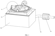
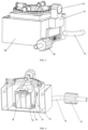
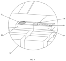
- FIGS. 1-5 are schematic structural diagrams of a fully immersed energy storage device according to a preferred embodiment of the present disclosure.
- the fully immersed energy storage device in this embodiment includes an energy storage device casing 10 and a water pump 32.
- An insulation box 11 is fixedly mounted inside the energy storage device casing 10.
- An assembly plate 12 is fixedly mounted on the insulation box 11.
- a mounting platform 13 is fixedly mounted on the assembly plate 12.
- An annular rack 14 is movably mounted on the assembly plate 12.
- a rotating groove 15 is formed between the mounting platform 13 and the annular rack 14.
- Balls 16 are movably placed inside the rotating groove 15.
- An assembly block 17 is fixedly mounted on the mounting platform 13.
- a rotating shaft 18 is movably mounted on the assembly block 17. One end of the rotating shaft 18 is fixedly provided with a gear 19.
- the gear 19 and the annular rack 14 are assembled through tooth meshing.
- the other end of the rotating shaft 18 is movably connected with a first assembly rod 20.
- the first assembly rod 20 is movably connected with a second assembly rod 23.
- the second assembly rod 23 is movably connected with a fixed block 24.
- the fixed block 24 is movably connected with an energy storage box 25.
- An energy storage battery pack 26 is provided inside the energy storage box 25.
- a spring slot 27 is fixedly provided on the energy storage box 25.
- a spring 28 is fixedly received in the spring slot 27.
- the other end of the spring 28 is fixedly connected to a buckle 29.
- a buckle block 30 is fixedly mounted on the energy storage box 25.
- a buckle slot 31 is defined in the buckle block 30, and the buckle 29 is received in the buckle slot 31.
- a motor base 21 is fixedly mounted on the energy storage device casing 10.
- the first motor 22 is fixedly mounted on the motor base 21.
- the output end of the first motor 22 is fixedly assembled
- a method for controlling the fully immersed energy storage device includes the following steps S1-S3.
- each gear 19 drives the first assembly rod 20 to move via the rotating shaft 18, and the relative movements of the first assembly rods 20 and the second assembly rods simultaneously act on the four sides of the energy storage box 25, causing the energy storage box 25 to move up and down.
- the working principle is as follows.
- the first motor 22 is started, and the rotation of the gear 19 drives the annular rack 14 to rotate.
- the three additional gears 19 can rotate at the same time, thus the first assembly rods 20 are driven to rotate through the connected rotating shafts 18.
- the cooperation of the first assembly rods 20 and the second assembly rods 23 can make the energy storage box 25 move up and down, such that the energy storage box 25 can be completely immersed in the coolant in the insulation box 11, and the energy storage box 25 can also be moved out of the insulation box 11 so that the energy storage battery pack 26 can be repaired and replaced. Installing multiple energy storage battery packs 26 in the energy storage box 25 can increase the capacity of the energy storage device, so that it can supply energy for a long time.
- the insulation box 11 is filled with coolant, which is a non-conductive oil, ensuring that the energy storage box 25 is in a stable temperature state.
- FIGS. 4-8 are schematic structural diagrams of a fully immersed energy storage device according to another preferred embodiment of the present disclosure. Coolant can keep the device at a stable temperature, but for the device that continuously generates heat, it is necessary to dissipate the heat from the energy storage device in time.
- one end of the water pump 32 is fixedly equipped with a water inlet pipe 33.
- a diverter 34 is fixedly mounted inside the energy storage device casing 10.
- the water inlet pipe 33 passes through the energy storage device casing 10 and is fixedly assembled with the diverter 34.
- a second motor 35 is fixedly mounted inside the diverter 34. The output end of the second motor 35 is fixedly connected with a screw rod 36.
- the screw rod 36 is movably equipped with a movable cover 37.
- the diverter 34 is fixedly connected with a first diverter pipe 38.
- the first diverter pipe 38 is fixedly equipped with a condensation plate 39.
- Condensation pipes 40 are fixedly installed inside the condensation plate 39.
- the condensation plate 39 is fixedly equipped with a return pipe 41.
- the return pipe 41 is fixedly connected with a collector 42.
- the diverter 34 is fixedly connected with a second diverter pipe 43.
- the other end of the second diverter pipe 43 is fixedly connected with the collector 42.
- the collector 42 is fixedly connected with a water outlet pipe 44, which passes through the energy storage device casing 10.
- a method for controlling a fully immersed energy storage device includes the following steps S4-S7.
- the water pump 32 pumps the cooling water into the energy storage device through the water inlet pipe 33 and then discharges the cooling water through the water outlet pipe 44, thereby taking away the heat in the device.
- the working principle is as follows.
- the water pump 32 is started to pump water into the second motor 35 through the water inlet pipe 33.
- the second motor 35 is started to drive the screw rod 36 to rotate, so that the movable cover 37 is moved to the top of the second motor 35.
- the cooling water will be injected into the collector 42 through the second diverter pipe 43 and then discharged through the water outlet pipe 44.
- the second motor 35 is started to drive the screw rod 36 to rotate to move the movable cover 37 to the bottom of the second motor 35.
- the cooling water will flow out through the first diverter pipe 38 and the second diverter pipe 43 respectively.
- the cooling water flowing out from the second diverter pipe 43 will be injected into the collector 42.
- the cooling water flowing out from the first diverter pipe 38 will enter the plurality of condensation pipes 40 inside the condensation plate 39, thereby effectively cooling the energy storage device. Then it is injected into the collector 42 through the return pipe 41, and the cooling water in the collector 42 is then discharged through the water outlet pipe 44.
- the functions/operations mentioned in the block diagrams may be carried out in a different order than the order mentioned in the operation diagram.
- two blocks shown in succession may in fact be executed substantially simultaneously or the blocks may sometimes be executed in the reverse order.
- the embodiments presented and described in the flow diagrams of the present disclosure are provided by way of examples to provide a more comprehensive understanding of the technology. The disclosed methods are not limited to the operations and logical flows presented herein. Alternative embodiments are foreseeable in which the order of various operations is changed and in which sub-operations described as part of a larger operation are performed independently.
- the functions are implemented in the form of software functional units and sold or used as independent products, they can be stored in a computer-readable storage medium.
- the technical solution of the present disclosure essentially or the part that contributes to the existing technology or the part of the technical solution can be embodied in the form of a software product.
- the computer software product is stored in a storage medium and includes several instructions configured to cause a computer device (which may be a personal computer, a server, or a network device, etc.) to execute all or part of the steps of the methods described in various embodiments of the present disclosure.
- the aforementioned storage medium includes USB flash disk, mobile hard disk, read-only memory (ROM), random access memory (RAM), magnetic disk, optical disk, or other medium that can store program code.
- a "computer-readable medium” may be any device that can contain, store, communicate, propagate, or transport a program for use by or in connection with an instruction execution system, apparatus, or device.
- the computer-readable medium include: electrical connection (electronic device) with one or more wires, portable computer disk cartridge (magnetic device), random access memory (RAM), read-only memory (ROM), erasable and programmable read-only memory (EPROM) or flash memory, fiber optic devices, and portable compact disc read-only memory (CDROM).
- the computer-readable medium may even be paper or other suitable medium on which the program may be printed, as the program can be obtain electronically by, for example, optically scanning the paper or other medium, followed by editing, interpreting, or processing in other suitable ways when necessary, and then being stored in a computer memory.
- various parts of the present disclosure can be implemented using hardware, software, firmware, or a combination thereof.
- various steps or methods can be implemented using software or firmware stored in a memory and executed by a suitable instruction execution system.
- a suitable instruction execution system For example, if it is implemented using hardware, as in another embodiment, it can be implemented by any one or a combination of the following technologies known in the art: discrete logic circuits with logic gate circuits for implementing logical functions on data signals, application-specific integrated circuits with suitable combinational logic gate circuits, programmable gate array (PGA), field programmable gate array (FPGA), etc.
Landscapes
- Chemical & Material Sciences (AREA)
- Chemical Kinetics & Catalysis (AREA)
- Electrochemistry (AREA)
- General Chemical & Material Sciences (AREA)
- Engineering & Computer Science (AREA)
- Manufacturing & Machinery (AREA)
- Other Liquid Machine Or Engine Such As Wave Power Use (AREA)
- Hydraulic Turbines (AREA)
Applications Claiming Priority (2)
| Application Number | Priority Date | Filing Date | Title |
|---|---|---|---|
| CN202310369670.XA CN116487796B (zh) | 2023-04-07 | 2023-04-07 | 一种全浸没式储能设备 |
| PCT/CN2023/113056 WO2024207658A1 (zh) | 2023-04-07 | 2023-08-15 | 一种全浸没式储能设备 |
Publications (3)
| Publication Number | Publication Date |
|---|---|
| EP4465425A1 true EP4465425A1 (de) | 2024-11-20 |
| EP4465425A4 EP4465425A4 (de) | 2025-04-23 |
| EP4465425B1 EP4465425B1 (de) | 2026-05-06 |
Family
ID=87226139
Family Applications (1)
| Application Number | Title | Priority Date | Filing Date |
|---|---|---|---|
| EP23794232.1A Active EP4465425B1 (de) | 2023-04-07 | 2023-08-15 | Vollständig eingetauchte energiespeichervorrichtung |
Country Status (4)
| Country | Link |
|---|---|
| US (1) | US20250079568A1 (de) |
| EP (1) | EP4465425B1 (de) |
| CN (1) | CN116487796B (de) |
| WO (1) | WO2024207658A1 (de) |
Families Citing this family (1)
| Publication number | Priority date | Publication date | Assignee | Title |
|---|---|---|---|---|
| CN116487796B (zh) * | 2023-04-07 | 2023-10-17 | 南方电网调峰调频(广东)储能科技有限公司 | 一种全浸没式储能设备 |
Family Cites Families (11)
| Publication number | Priority date | Publication date | Assignee | Title |
|---|---|---|---|---|
| CN106252701A (zh) * | 2016-08-30 | 2016-12-21 | 天能电池(芜湖)有限公司 | 蓄电池水浴槽的保护装置 |
| JP7091775B2 (ja) * | 2018-03-30 | 2022-06-28 | トヨタ自動車株式会社 | 電池パック |
| CN209994101U (zh) * | 2019-06-14 | 2020-01-24 | 湖北雷特防雷检测有限公司 | 一种电源电涌保护器自然保护装置 |
| US11552345B2 (en) * | 2019-08-20 | 2023-01-10 | Baidu Usa Llc | Power architecture design for thermal management of battery backup energy storage |
| CN111729222A (zh) * | 2020-06-18 | 2020-10-02 | 速博达(深圳)自动化有限公司 | 防爆灭火装置 |
| CN214230341U (zh) * | 2020-12-04 | 2021-09-21 | 杭州定立工贸有限公司 | 一种可进行伸缩占用空间小的电竞桌 |
| CN215617763U (zh) * | 2021-06-15 | 2022-01-25 | 山东日照发电有限公司 | 一种新能源电池装配装置 |
| CN215185305U (zh) * | 2021-06-30 | 2021-12-14 | 南昌航空大学 | 一种配电柜 |
| CN115693002A (zh) * | 2021-07-30 | 2023-02-03 | 蔚来汽车科技(安徽)有限公司 | 电池包以及对电池包进行热管理的方法 |
| CN114054374A (zh) * | 2021-11-18 | 2022-02-18 | 李慧玲 | 一种食品药品质量分级快速检测装置 |
| CN116487796B (zh) * | 2023-04-07 | 2023-10-17 | 南方电网调峰调频(广东)储能科技有限公司 | 一种全浸没式储能设备 |
-
2023
- 2023-04-07 CN CN202310369670.XA patent/CN116487796B/zh active Active
- 2023-08-15 US US18/563,004 patent/US20250079568A1/en active Pending
- 2023-08-15 WO PCT/CN2023/113056 patent/WO2024207658A1/zh not_active Ceased
- 2023-08-15 EP EP23794232.1A patent/EP4465425B1/de active Active
Also Published As
| Publication number | Publication date |
|---|---|
| WO2024207658A1 (zh) | 2024-10-10 |
| CN116487796B (zh) | 2023-10-17 |
| US20250079568A1 (en) | 2025-03-06 |
| CN116487796A (zh) | 2023-07-25 |
| EP4465425A4 (de) | 2025-04-23 |
| EP4465425B1 (de) | 2026-05-06 |
Similar Documents
| Publication | Publication Date | Title |
|---|---|---|
| EP4465425A1 (de) | Vollständig eingetauchte energiespeichervorrichtung | |
| CN207641541U (zh) | 一种废旧电器配件二级粉碎设备 | |
| US20170020019A1 (en) | Failure safe power source for solid state disk drives | |
| CN119153849A (zh) | 一种光伏储能微电网系统的电能转换设备 | |
| CN101364138A (zh) | 固态硬盘存储系统电源管理方法和装置 | |
| CN118782852B (zh) | 液流电池的双极板与导流框总成 | |
| CN115309247A (zh) | 一种便于散热的工控机 | |
| CN211712019U (zh) | 一种轴承自动上料机构 | |
| CN215643701U (zh) | 一种云存储高速固态硬盘 | |
| CN117673553A (zh) | 一种安全高效的级联型高压链式储能系统 | |
| CN116483140A (zh) | 一种储能设备均温控制系统 | |
| CN221668521U (zh) | 一种用于技术开发的便捷数据存储装置 | |
| CN116161367A (zh) | 一种电池立体存储组件 | |
| CN107765829A (zh) | 一种可均匀散热的计算机主机箱 | |
| CN210166704U (zh) | 一种便于理线的计算机机箱 | |
| CN219281860U (zh) | 一种利用凉水塔水流下落的发电装置 | |
| CN222050852U (zh) | 一种服务器浸没式液冷装置 | |
| CN113811132A (zh) | 一种云计算机用高效冷却机柜装置 | |
| CN212460492U (zh) | 一种基于区块链电子发票的管理装置 | |
| CN218069989U (zh) | 一种电池簇热管理设备 | |
| CN219442864U (zh) | 一种具备防尘机构的控制器 | |
| CN220368967U (zh) | 一种双向直流电源调压装置 | |
| CN222464176U (zh) | 一种便携式双向pd快充移动电源 | |
| CN216894952U (zh) | 一种长轴液下泵保护装置 | |
| CN220820571U (zh) | 一种散热除尘装置 |
Legal Events
| Date | Code | Title | Description |
|---|---|---|---|
| STAA | Information on the status of an ep patent application or granted ep patent |
Free format text: STATUS: UNKNOWN |
|
| STAA | Information on the status of an ep patent application or granted ep patent |
Free format text: STATUS: THE INTERNATIONAL PUBLICATION HAS BEEN MADE |
|
| PUAI | Public reference made under article 153(3) epc to a published international application that has entered the european phase |
Free format text: ORIGINAL CODE: 0009012 |
|
| STAA | Information on the status of an ep patent application or granted ep patent |
Free format text: STATUS: REQUEST FOR EXAMINATION WAS MADE |
|
| 17P | Request for examination filed |
Effective date: 20231103 |
|
| AK | Designated contracting states |
Kind code of ref document: A1 Designated state(s): AL AT BE BG CH CY CZ DE DK EE ES FI FR GB GR HR HU IE IS IT LI LT LU LV MC ME MK MT NL NO PL PT RO RS SE SI SK SM TR |
|
| A4 | Supplementary search report drawn up and despatched |
Effective date: 20250321 |
|
| RIC1 | Information provided on ipc code assigned before grant |
Ipc: H01M 10/6568 20140101ALI20250317BHEP Ipc: H01M 50/264 20210101ALI20250317BHEP Ipc: H01M 50/209 20210101AFI20250317BHEP |
|
| GRAP | Despatch of communication of intention to grant a patent |
Free format text: ORIGINAL CODE: EPIDOSNIGR1 |
|
| STAA | Information on the status of an ep patent application or granted ep patent |
Free format text: STATUS: GRANT OF PATENT IS INTENDED |
|
| DAV | Request for validation of the european patent (deleted) | ||
| DAX | Request for extension of the european patent (deleted) | ||
| INTG | Intention to grant announced |
Effective date: 20251219 |
|
| GRAS | Grant fee paid |
Free format text: ORIGINAL CODE: EPIDOSNIGR3 |
|
| GRAA | (expected) grant |
Free format text: ORIGINAL CODE: 0009210 |
|
| STAA | Information on the status of an ep patent application or granted ep patent |
Free format text: STATUS: THE PATENT HAS BEEN GRANTED |